Creating Spatial Temporal Database by Autonomous ...
Recommend Documents
tool for representing linear attributes and events, is commonly viewed as an aspect of ..... Sutton, J. C., and M. M. Wyman, Dynamic location: an iconic model to ...
decaying Syrian economy and the inflow of refugees from conflict areas. Keywords: marketing information system, citrus, temporal arbitrage, Lattakia, Syria.
database image, will then integrate these atomic spatial similarity assessments and ...... degree-increment, mirroring, inclusion of new object(s) and removal of ...
large geospatial data sets and their applications in location prediction, spatial outliers detection and co-location association rules mining. Keywords: co-location ...
Fora da regi˜ao equatorial, as mudanças do OLR eram pequenas durante os eventos ENSO e insignificante nos outros anos. Em algumas longitudes,.
3 Department of Finance, Real Estate and Law, California State Polytechnic University, Pomona. (E-mail: ... amenity (a ten mile stretch of ten-lane interstate highway), in the absence of other important ...... Kong F, Yin H, Nakagoshi N. 2007.
waving trees, spouting fountain and camera jitters, which causes the significant performance degradation of traditional methods. In this paper, a novel ...
Ralf Hartmut Güting, Tutorial Spatial Database Systems. 1 What is a Spatial
Database System? Requirement: Manage data related to some space. Spaces:.
Database Application. Borland Software Corporation. 100 Enterprise Way, Scotts
Valley, CA 95066-3249 www.borland.com. Borland®. Delphi™ 7 for Windows ...
For subdivisioning of a body using positional information,. Wolpert (1968) proposed a French-flag model. The model is composed of three stripes with different ...
Chomicki for checking dynamic database integrity constraints into a situation- ... By doing this, we are able to: (1) Answer queries about a whole hypothetical evo ...
Motivation comes from the self, not from a desire for money. ..... a mandate for
change and improvement (e.g., ―your delivery times are down — you've ..... http:/
/www.imdb.com/title/tt0075686/quotes, Owner: Amazon, Inc., Access Date:.
Dec 17, 2010 - Abstract The paper reports work to create believable autonomous Non Player Characters in Video ... ters based on a biologically-inspired theory of human action regulation taking into account ...... Amsterdam: IOS. Press. 21.
New GNC capability is needed to rendezvous with and land on small bodies. (Shown: Lander.) One of the means currently proposecl for implementing capable, ...
Finally, this all must be done in real time, so that if the music changes or ... Tohoku University, which was designed to perform ballroom dances with human ...
Dec 17, 2010 - e-mail: [email protected]. J. Dias · A. ... 2 http://fallout.bethsoft.com/eng/home/home.php. 123 ...... In Proceedings of the game developer's.
document any software (including IP arrangements), algorithms, ...... of the participants used an Apple computer running OS X. The participants completed both the ...... That vocabulary in turn would sub-class the CIDOC CRM ontology in.
Jul 25, 2017 - steering techniques, sliding spotlight and staring spotlight modes have .... we need to change the PRF for the green pulse, because 4030 Hz is not .... closer to the beginning of the receive window, eventually running out of the.
Nov 20, 1998 - Master of Science. In. Biological Systems Engineering ... concept implemented in a geographic information system (GIS). The goal of this study.
Sep 17, 2014 - Using a conditional double knock-out strategy, we demonstrate that prosensory ..... viously been shown that, in Hes/Hey compound mutants, in.
in HC (59% foreign born, 1325/2251) [1]. This finding is a departure from the national trends that ..... Association NTC. Guide to the application of genotyping to ...
âsmaller partsâ of Sam, like his brain and hearth, do not count as temporal ..... If not, then 2.2 fails in S3 for the same reason it failed in S2: synchronic parts of y ...
GEO-REFERENCED PHOTO ALIGNMENT. Paul Chippendale, Michele ... to estimate vanishing points and the presence of occluding objects. Unfortunately ...
Creating Spatial Temporal Database by Autonomous ...
Spatial Temporal GIS Part1). Abstractâ This study describes mobile robot surveillance system using spatial temporal GIS. This paper specially describes the ...
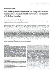
Creating Spatial Temporal Database by Autonomous Mobile Surveillance System (A Study of Mobile Robot Surveillance System using Spatial Temporal GIS Part1) Jun-ichi Meguro Kiitirou Ishikawa Yoshiharu Amano Takumi Hashizume
Jun-ichi Takiguchi Michinori Hatayama Ryujirou Kurosaki Kyoto University Mitsubishi Electric Corporation Disaster Prevention Research Institute Kamakura Works Gokasho, Uji-shi, Kyoto, Japan 325, Kamimachiya, Kamakura-shi, [email protected] Waseda University Kanagawa, Japan Advanced Research Institute for [email protected] Science and Engineering 17, Kikui-cho, Shinjyuku-ku, Tokyo, Japan [email protected] Abstract— This study describes mobile robot surveillance system using spatial temporal GIS. This paper specially describes the method of collecting spatial temporal data by an autonomous mobile robot system used in a factory premises with some high-rise buildings. This system consists of a wireless LAN network, a base station and an autonomous vehicle. The vehicle is equipped with a GPS/INS navigation system using the network-based Real-Time Kinematic GPS (RTK-GPS) with Positioning Augmentation Services (PASTM, Mitsubishi Electric Corporation 2003), an Area Laser Radar (ALR), a slaved camera, and an Omni-Directional Vision (ODV) sensor for surveillance and reconnaissance. The vehicle switches control modes according to the vehicle navigation error. It has three modes, “Normal”, “Road tracking”, and “Crossing recognition”. A field test result shows that the vehicle can track the planned-path within 0.10[m] accuracy at straight paths and within 0.25[m] for curved paths even if RTK fixed solutions are not available. Field experiments and analyses have proved that the proposed navigation method can provide sufficient navigation and guidance accuracy under poor satellite geometry and visibility. Omni-directional image and ALR’s scan data, which is synchronized with both position and GPS time, is memorized as spatial temporal. This spatial temporal data enables the operator to search everywhere in the factory premises efficiently by way of arbitrary position or measured time. The field test reveals that the spatial temporal database is confirmed to be useful for remote surveillance.
I. INTRODUCTION Recently, although various mobile surveillance robots have been developed [1][2], the effective information management technique which can manage time-series data effectively, is not proposed. Moreover, robots which are used in outdoor environment generally use a carrier phase differential global positioning system (GPS) aided by low-cost inertial navigation system (INS)[3][4][5], but most of the researches which use a carrier phase
differential GPS assume that the operational environment has few obstructions that may cause a GPS satellite blockage. Namely the system is supposed to work in a cultivated land, an airport or a large warehouse area with low buildings. However in an urban canyon, there are situations where the satellite signal is seriously restricted by various obstacles. That is, before the signal arrives at the receiver, it may be blocked, reflected, delayed, attenuated, or scattered by a terrestrial obstacle or a tall building. These influences severely degrade GPS positioning accuracy and make it difficult to implement GPS-based navigation system in such an area. In this research, a robust mobile robot navigation/guidance system that can navigate in such a severe environment was developed. Furthermore, we propose effective database analyzing method based on precise time and position using a Spatial Temporal GIS. In this paper, the proposed vehicle navigation/guidance system and the image data analyzing method of the mobile surveillance system is evaluated in a factory premises with some tall buildings. II. SYSTEM DESCRIPTION The proposed system consists of a wireless LAN network, a base station, and an autonomous vehicle. The vehicle is equipped with a GPS/INS navigation system using the network-based Real-Time Kinematic GPS (RTK-GPS) with Positioning Augmentation Services (PAS), an ALR for a real-time map building, a CCD camera (slaved camera), and an Omni-Directional Vision (ODV)[6] sensor for surveillance and reconnaissance. The system’s configuration is shown in Fig.1. Product name of the sensors is shown in Table1. The network-based RTK-GPS mobile terminal called “Position IT”, which has a user console with a wireless LAN modem, is used to know route conditions such as a temporal traffic restriction.
It is designed to be used as a conventional traffic restriction corn and can calculate its position by a GPS receiver in it. Also it can send its position and the traffic information by the wireless LAN to the base station. Then, the autonomous vehicle uses that information to modify its path and velocity. Positioning Augmentation Services (PAS)[7], which is offered by Mitsubishi Electric Corporation, uses GPS observation data from the GEONET of the Geographical Survey Institute, and generates Geo++ Flachen Korrektur Parameter (FKP) approximated in tangential flat plane. The data from the PAS service enables the user to create virtual GPS observation data at a virtual reference point. The outline of PAS system is shown in Fig.2. A base station consists of two PCs and a joystick. A vehicle control screen at the base station shows the planned path, the vehicle trajectory, and various vehicle status including vehicle control modes, network conditions, GPS measurement performance and so on (Fig.3). On this screen, the operator can control the vehicle and survey large area from remote places. While the vehicle follows its planned path, live images from it are shown in three 16 inches monitors at the base station for surveillance purposes. One of the images is a panoramic ODV image and the other is from the slaved camera, which shows close look of Region-Of-Interest (ROI).
Fig.2 PAS system and services.
Internet
Fig.3 Base station GUI.
PAS data center Geo Net Appearance Wireless LAN GUI
Real-time Serveillance image database server surveillance view Base station
Table 1 Sensor configuration. Loaded sensor Product name GPS Antenna GeodeticIV (Thales Navigation) GPS Receiver Z-Xtreme(Thales Navigation) MEMS-INS AHRS400cc-100(Crossbow) PLS-101(SICK) ALR Omni-directional Vision ODV(Mitsubishi Electric Corp.) III. ROUTE RE-PLANNING BASED ON LOCAL INFORMATION
Position IT
Wireless LAN Wireless LAN Antenna GPS Antenna ODV Slaved camera
ALR
Vehicle
Fig.1 System configuration.
The coordinate of all buildings in the field is shown as red points in Fig.5. They were precisely surveyed by an RTK-GPS, and the buildings were modeled as a convex polygon. The base station stores the field data and uses them for the route planning. The current vehicle position is registered as “Start” point and the “Goal” is designated by a mouse-click on the filed map using an aerial photograph. Then, the MAKLINK graph[8], known as a high-speed domain division method, is used to generate the shortest route. The route planning procedure is illustrated in Fig.4. In a case of unexpected traffic restriction, it is difficult to update the map information immediately. Moreover it is unreal to find detour route autonomously only by vehicle sensors. Hence, “Position IT” is used to get real-time traffic information. If several “Position IT” are put on the roadside, an area surrounded by them is added to the original digital map as an obstacle. Then, route re-planning
is executed to find a new route, which can bypass the blocked path as shown in Fig.5. Furthermore, “Position IT” can be programmed to set “Going-slowly zone” to reduce the vehicle’s speed for a while.
Where force vector f b in body frame, body rate ω nbb = ω x ω y ω z , earth rate ω ien , transport rate ω enn ,
[
]
and earth gravity g n in navigation frame are used. The extended Kalman filter has 15 states, which is position error δp , velocity error δv n , attitude error ε n , acceleration bias x a , and gyro bias x g .
[
x = δp δv n ε n
Fig.5 Detour route planning using information from Position IT. IV. LOOSELY COUPLED RTK-GPS/INS NAVIGATION The navigation system integrating a low cost MEMS INS and a high performance RTK-GPS receiver is currently investigated intensively. It will be used in wide variety of mobile systems if modernized GPS, Quasi-Zenith Satellite System, and Galileo become available and also GPS receiver prices become reasonable for most civilian users. The GPS/INS presented in this paper consists of strapdown navigation calculation and an extended Kalman filter[12]. Fig.6 shows a block diagram of the loosely coupled GPS/INS. The Kalman filter formulation is defined in discrete form as approximation of continuous system. The equations, which are employing quaternion based strapdown algorithms, for position (latitude, longitude, altitude), velocity (north, east, down), and attitude (quaternion) are formulated in local NED frame.
xa
xg
]
T
( 2)
The filter is implemented in feedback form, and the error in strapdown inertial navigation and sensor bias of an INS can be compensated. The system equation is defined as :
d x = Fx(t) + w dt
(3)
Where F is the system matrix and w is the process noise. It is converted to the discrete form using Tailor series expansion. The measurement equation is defined as follows: z = H(t, y )x(t ) + v(t )
( 4)
The position and speed difference between the GPS receiver output and strapdown navigation output is used as the measurement residual.
[
Z = δnˆ δeˆ δhˆ δvˆ N
δvˆ E δvˆ H
]
T
(5)
Fig.7 shows post-processing result, which used logged data of a certain field test by a motorcar loaded RTK-GPS/INS. The RTK-GPS positioning is interrupted due to satellite signal blockage by a gate. The trajectory
calculated by INS measurements exhibits gradual deviation from the true path due to the acceleration bias and gyro bias. Moreover, large body rate input causes sharp trajectory error. On the other hand, in the GPS/INS case, a continuous and smooth trajectory can be obtained. GPS Fix GPS Float INS GPS/INS
bigger its absolute value, the higher its reliability. Let R represents the distance between Points A to B, l represents a distance to a certain point on line segment AB, and ε represents error contained in ALR sensing data. The probability is expressed as follows. Probability that an object does not exist:
l 2 Pe (l ) = − 1 − R − ε
(0 ≤ l ≤ R − ε )
( 6)
Probability that an object exists:
{
}
P0 (l ) = −ε 2 l 2 − 2 Rl + ( R 2 − ε 2 ) ( R − ε ≤ l ≤ R + ε ) (7) w
East position m
Fig.7 GPS/INS post-processing simulation.
W A
l tan( W/2)
B l
l
P
R
-l tan( W/2) R+e
V. REAL-TIME ENVIRONMENTAL MAP USING AN ALR AND THE SELF-POSITION In a real operative environment, there are many obstacles, which are not indicated on the map, e.g. parking cars, pedestrians and so on. Real-time environmental map which shows relative range information toward obstacles is essential for a local deviation path calculation for obstacle avoidance or for a self-positioning by the landmark recognition method. Recently, there are several related research works based on the simultaneous localization and map building (SLAM) method[9][10]. The main advantage of SLAM is that it doesn't need artificial infrastructures for guidance or a priori topographical knowledge of the environment. In this proposed system, however, the cm-class precise digital map and the absolute-position-based pre-planned route are already known. Therefore, it is quite reasonable to propose a unique real-time environmental map building method featuring object's existence probability voting process, which has robustness toward Laser light reflectance of surrounding buildings or trees. The ALR’s range information on a 180 [degree] front domain together with the absolute position obtained by the GPS/INS becomes an environmental map. The occupancy grid[13] on the ENU coordinates is used to accumulate object's existence probability by voting process of ALR range data. That image contains a continuum of probability values before it is quantized to obtain a digital image. By quantizing the probability values at 256 different grey levels, it becomes possible to apply normal image processing procedure. Suppose that a vehicle is located in Point A and an object is located in Point B. The existence probability over the grid between Points A to B is defined as Fig.9. The initial value of the probability is set to zero. Then, the probability takes a negative value when any object doesn't exist, otherwise it takes a positive value. The
w
P e (l)
R-e
P P o(l) B
A l R-e
l
R R+e
P e (l)
Fig.8 ALR’s probability model. Where, it is assumed that the probability is uniformly distributed in the perpendicular direction to laser beam. Then, the existence probability calculated by (6) and (7) are voted to each grid point (xi , yi ) , which is obtained by measuring range data; li and beam angle; α i . Thus, an environmental map with square region (30x30 [m]) is created based on this definition. As an example, an environmental map obtained in a crossing while running at about 4 [km/h] in complicated outdoor environment is shown in Fig.9. The vehicle continuously recognizes its surroundings by updating the same scale environmental map. It can be said that the edges of the surrounding building are clearly obtained. The main advantages of this method are robustness toward Laser light reflectance of a surrounding buildings and manageability with a relative error to a fixed value. For example, even if the self-position error increases due to the GPS satellite blockage, the relative distance error to a surrounding obstacle always settles in a relatively small amount. This enables the Local Path Planner to generate modified course for obstacle avoidance or to identify the self-position by matching with the map obtained in advance. The relative distance error to buildings or trees was about 0.3[m] in Fig.9.
Threshold level
Fig.12 Crossing recognition result. VII. GUIDANCE METHOD BY CONTROL MODE TRANSMISSION
Fig.9 Example of an environmental map. VI. LOCAL PATH PLANNING AND SELF-POSITION IDENTIFICATION BY MAP MATCHING
The proposed local path planner for obstacle avoidance and crossing identification method features robustness toward the sensor noise or environmental complexity, and the H/W implementation simplicity by composite use of general image processing technique. Fig.10 shows the local path generation flow. Firstly, the environmental map is applied to a “Thresholding” operation at some probability level, and is applied to “Expanding and Shrinking” process until the noise is removed. Secondly, free space in which a vehicle can go through is extracted as a set of dots with “Thinning” operation. Then, Hough Transformation is applied to convert a set of dots into a polar form of a line. Hence the subgoals, coordinates of the target route, are estimated in real-time, which enable road tracking or obstacle avoidance. Suppose that a sequence of intersections along with the planned path is memorized with subgoals beforehand. By applying template matching operation to the obtained image, crossing recognition can be performed. Fig.11 shows the crossing image templates and Fig.12 shows an example of crossing recognition result. Four kinds of templates; “Going straight”, “Left-turn-crossing”, “Right-turn-crossing”, “T junction”, and “Crossing of a cross” are prepared and applied periodically. Template No.4 is selected as the recognition result for Fig.10’s case.
The proposed vehicle guidance features hierarchical compound use of a RTK-GPS/INS, the road tracking based on a real-time environmental map, and the crossing-based route guidance to establish robust mobile robot navigation. In Fig.14, the task priority is revealed as a control system block diagram. If the crossing recognition process identifies an intersection, then it controls pre-planned subgoals and generates new subgoals which perform turning action or going straight action. If the free space extraction or road tracking process finds an obstacle within certain range, it controls other subgoals and sends new subgoals which can satisfy road tracking or obstacle avoidance. That is, there are three control modes, “Normal”, ”Road tracking” and “Crossing recognition”. The vehicle can track pre-planned route safely by choosing the control mode autonomously.
Fig.13 Vehicle guidance/Control system. a. Obstacle recognition on planned route
Normal a Road tracking
c
b c d
Crossing recognition
b. No obstacles on planned route c. Crossing pattern matching success d. Secession from intersection
Fig.14 Control mode translation.
Generated map
Binarization
Expanding & Shrinking
Thresholding
Template matching Hough transformation
Fig.10 Image processing procedure.
1. Straight
2. L_cross
3. T_cross
4. X_cross
Fig.11 Crossing image template.
VIII. FIELD EXPERIMENT AND EVALUATION FOR NAVIGATION/GUIDANCE PERFORMANCE The proposed vehicle navigation method was implemented and evaluated in a mobile surveillance system in a factory premises. The vehicle’s route tracking error on “Normal mode” was evaluated in a test course and is shown in Fig.15 and Fig.16. Each character shows the corresponding point in each figure. It can be said that the vehicle can track the planned-path within 0.10[m] accuracy at straight paths and within 0.25[m] for curved paths. “Road tracking mode” performance was shown in Fig.17. The typical usage of this mode is for obstacle avoidance. Blue line shows a pre-planned route and red line shows the actual vehicle trajectory. It can be said that
the vehicle can successfully evade obstacles and can go back to pre-planned path afterward without occurrence of transitional error.
North position
m
20
E
10 0
C
F
B
D
-10
A
-20
Wireless LAN antenna
G
-30 -120
-100
-80
-60
-40
-20
0
route. In each point, the vehicle could follow the route even if the self-position error was increased due to the GPS satellite blockage by smooth control mode transmission. It can be said that the proposed navigation method can successfully navigate the vehicle along with the pre-planned path in spite of poor satellite geometry and visibility.
20 Route is made by the MAKLINK graph method
East position m
Fig.15 Planned route.
Base statioin Goal Start
Error m
0.30
7
0.20 0.10 0.00
E F
B
G
C A 0
D
50
300 [m] 1
Rout e
A 100
150
200
250
300 [m]
Time s
Fig.16 Vehicle route tracking error.
Fig.18 Evaluation field.
6 5 ~0 7~ Number of satellite
100 m
0
Fig.17 Vehicle locus in collision avoidance experiment. Fig.18 shows another evaluation field and Fig.19, 20 shows the vehicle’s route tracking performance with two typical satellite geometry. The route is made by the MAKLINK graph method. Fig.19 shows corresponding number of satellite and PDOP for each case. The height of each building is also described. In case A, an excellent satellite geometry was obtained with the average number of satellites exceeded more than 5, and PDOP was less than 5 as shown in Fig.19. Thus, precise self-position was obtained as shown in Fig.20. However, there were two points where no GPS solution was available due to satellite blockage by the gate structure as shown in Fig.18. It can be said that the RTK-GPS/INS can update the self-position seamlessly even if RTK fixed solutions are not available. Case B shows poor satellite geometry with PDOP larger than 6 as shown in Fig.19. In this case, there were some points where RTK-GPS fixed solutions were available from the GPS receiver as shown in Fig.20. Additionally, lower right part of Fig.20 shows the corresponding environmental map which was obtained from reactive range information. On the point of α , “Road tracking mode” was executed because GPS signal outage caused large error accumulation in the RTK-GPS/INS. On the point of β , “Crossing recognition mode” was executed and the vehicle could successfully tracked the pre-planned
Case A.Excellent satellite geometry
Case B.Poor satellite geometry
Fig.19 Number of satellite and PDOP. Start/Goal
GPS solution type Control mode Normal Fix solution Road tracking Float solution Crossing recognition No solution
4.X_cross 5.X_cross
1.X_cross
3.X_cross 2.X_cross
Planned route
GPS solution type Control mode Normal Fix solution Road tracking Float solution Crossing recognition No solution
East position m Case A. Excellent satellite geometry
Control mode Normal Road tracking Crossing recognition
2.X_cross
East position m
East position m
Case B. Poor satellite geometry
Case B. Poor satellite geometry
Environmental map at β
Fig.20 Outdoor navigation result.
IX. Field experiment and evaluation for surveillance performance
c
Fig.21 shows the stored surveillance image. The 180 [degree] ODV image, which is updated at 4 [Hz] by way of wireless LAN, can contribute to obtain outline information at a glance. The slaved camera, which is designed to follow the target directed with the mouse on the ODV’s panorama image at the base station, is used to obtain expanded images of ROI (Region-Of-Interest).
a
a
b
Van Track
c Exist
Not exist
b
Enlargement of α
Fig.22 Example of spatial temporal data.
Panoramatic image
Slaved camera image
Fig.21 Real-time surveillance view. Furthermore, as every omni-directional image and ALR’s scan data, which is synchronized with both position and GPS time, is memorized as spatial temporal data and is utilized for crime prevention. This spatial temporal data (Fig.22) enables the operator to search everywhere in the factory premises efficiently by way of arbitrary position or measured time. Fig.24 shows the actual spatial temporal data which was collected by the autonomous vehicle. In this system, “KIWI+”[14][15] is used as the spatial temporal GIS database format. “KIWI+” has no explicit topological relation among object, and topological relation is generated with each query in real time. Thus, it is possible to analyze collected information easily on spatial and temporal. Fig.23 to Fig.24 show experimental results. Fig.25 shows the spatial temporal GIS’s GUI image. Right figure of Fig.22 shows the relative position of parking-cars which are located in α at Fig.23. These three panorama images are taken at the same place, from the same direction, but in different time. In picture “a”, a track and a van are seen as parking-cars. However, there was only the track in case “b” and both parking cars are disappeared in case “c” as time passes. In Fig.24, panorama images and corresponding laser range data which are taken in location A and B of Fig.23 are shown. In this case, a specific position search is carried out to watch anywhere in the field. It can be said that spatial temporal database is valuable for establishing virtual surveillance network which looks like the conventional fixed camera system. Furthermore, precise positions and omni-directional images make it possible to generate color-image-textured 3D model by the motion stereo technique. The omni-directional motion stereo is a unique mono stereo vision algorism which is described in detail[16] at “Part 2”. Fig.26 shows the idea of environmental recognition using 3D model obtained by the omni-directional motion stereo vision and the spatial temporal GIS, which are explained in detail at “Part 2”.
B's spatial temporal data Fig.24 Panorama images and corresponding range data.
that the proposed method can successfully navigate the vehicle along with the pre-planned route in spite of poor satellite geometry and visibility. Omni-directional image and ALR’s scan data, which is synchronized with both position and GPS time, is memorized as spatial temporal. This spatial temporal data enables the operator to search everywhere in the factory premises efficiently by way of arbitrary position or measured time. The field test reveals that the spatial temporal database is confirmed to be useful for remote surveillance.
REFERENCES
Fig.25 Spatial temporal GIS’s GUI.
Spatial temporal GIS 15
ALR sensing point
10
5
0
ODV's omni-directional image
-5
0 Xm
5
ALR's 180°scan data
synchronize GPS/INS's precise position & direction
3D model by "Motion stereo vision"
Environmental map
Fig.26 Environmental recognition using the spatial temporal GIS.
X. CONCLUSION In this paper, a new autonomous ground vehicle navigation/guidance and the method of analyzing collected data for the surveillance system, which can be used in a factory premises with some high-rise buildings, is presented. The proposed system consists of the wireless LAN network, PAS, a base station and an autonomous vehicle. In this research, the performance improvement of the navigation/guidance method under poor satellite visibility is presented. This was achieved by combining the network-based RTK-GPS/INS, the road tracking function based on a real-time environmental map, and the crossing-based route guidance. Field experiments reveal
[1]Ka Keung Lee, et al, A Multiagent Multisensor based Real-time Sensory Control System for Intelligent Security Robot, IEEE International Conf. on Robotics and Automation, 2003, Vol.2, 2394 2399 [2]N.tomatis, et al, Designing a Secure and Robust Mobile Interacting Robot for the Long Term [3]S.Sukkarieh, et al, A High Integrity IMU/GPS Navigation Loop for Autonomous Land Vehicle Application, IEEE Trans. on Robotics and Automation, Vol. 15 No.3, Jun. 1999, pp.572-578 [4]Burak H.Kaygisiz, GPS/INS Enhancement Using Neural Networks for Autonomous Ground Vehicle Applications, IEEE International Conf. on Robots and systems, 2003, pp3763-3768 [5]K.Ohno, et al, Outdoor Navigation of a Mobile Robot between Buildings based on DGPS and Odometry Data Fusion ,IEEE International Conf. on Robotics and Automation , 2003, Vol.2, pp1978-1984 [6]A.Takeya, et al, ”Omnidirectional Vision System Using Two Mirrors”, Novel Optical Systems Design and Optimization SPIE Vol.3430, pp.50-60, 1998 [7]M Saito, et al, Network-based RTK-GPS for Nation-Wide High Accuracy Positioning and Navigation in Japan, International Symposium International Space University, 2003 [8]H Asama, et al, A Method of Structuring Free Space And An Efficient Algorithm of Path Planning for Autonomous Mobile Robot, Annual Conference of the Robotics Society of Japan, 1990,pp881-882 ( Japanese) [9]M.W.M.Gamini Dissanayake, A Solution to the Simultaneous Localization and Map Building(SLAM) Problem, IEEE Transactions on Robotics and Automation, 17(3), 2001, pp229-241 [10]John J. Leonard, Hugh F. Durrant-Whyte, Simultaneous Map Building and Localization for an Autonomous Mobile Robot, Proc. of Int. Conf. on Intelligent Robots and Systems,1991,pp1442-1446 [11]T.Hashizume, et al, A Study of Autonomous Mobile System in Outdoor Environment, (Part5 Development of a Self-positioning System with an Omnidirectional Vision System, IEEE Int. Conf. Robotics and Automations, 2001 [12]R. Hirokawa, et al, Autonomous Vehicle Navigation with Carrier Phase DGPS and Laser-Scanner Augmentation, ION GNSS 2004 [13]A Elfes, et al, Sonar-Based Real-World Mapping and Navigation, J. of Robotics and Automation, 1987, pp.249-265 [14]KIWI+ homepage. URL:http://www.drm.jp/KiwiPLUS/index.htm [15]M. Hatayama, F. Matsuno, S. Kakumoto, H.Kameda, “Development of Spatial Temporal Information System DiMSIS”, Proc. Theory and Application of GIS, Vol.7, No.2, pp.25-33, 1999 [16]T.Hashizume, et al, Parking-vehicles Recognition using Spatial Temporal Data (A Study of Mobile Robot Surveillance System using Spatial Temporal GIS Part2), SSRR2005