ditions is challenging due to the lack of Fréchet differentiability of the ... results for optimal control problems governed by variational inequalities other than.
Creo 2.0 Parametric und Simulate Konfigurationsoptionen ... Änderungen an den
Konfigurationsoptionen von Creo Parametric 1.0 zu 2.0. 125. Creo 2.0 ...
Rudolph or Friedrich Försterling, Institut für Psychologie, Ludwig- ...... people; B. Paul is the kind of person that people like; C. Some other reason.â (p. 240).
Georg Nestmann. Ergänzungskurs Elementarmathematik für Bachelor WS2013/
2014. Klausurvorbereitung Teil II. Matrizen und Gleichungssysteme. 1. An 100 ...
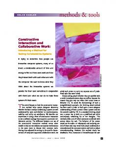
models is that our test subjects use separate workstations ..... folder to his private folder and then load it using the ... To test the tool, constructive interaction was.
Figure 1: The clinching of sheet steels. Interesting parameters are strain and stress inside the two materials under different distri- butions of clinches. In figure 2 ...
scribe in Section 5.1 how to find optimal parameterized reduced-order models for a special case ..... Define f(s, p) = A(s, p)â1B(p)b and gT (s, p) = cT C(p)A(s, p)â1. ... So, we may calculate a directional derivative and evaluate at s = Ï and p
Introduction 0. Neurocognition. Introduction 1. Dayan, P. & Abbott, L.,. Theoretical
Neuroscience,. MIT Press, 2001. Literature. Hyvärinen, A., Karhunen, J., &.
SAP-Sicht. Die zentralen Objekte der Finanzbuchhaltung bilden Konten, zu
welchen jeweils Stammdatensätze hinterlegt werden müssen. Erst dann können.
Form von Wassertröpfchen o. a.) oder Eis vorhanden. 1.1.1 Luftzustände im h,x-
Diagramm. Für die Berechnung im Programm wurde festgelegt: • t ≥ 0,01 °C: ...
Driving (EAGD) system for real time optimization and reduction of CO2 emission and ... (EAGD) with the aim to optimize t
Fluoride (AlF3) layer involved can be implemented as final process in solar cell .... a Fluorine (F) deficiency is accomplished at the in- terface AlF3|| SiO2 [3, 4, 5).
The tutorial con- cludes by giving a prototype for cluster middleware based on CORBA for heterogeneous clu- ster. ... System monitoring for ... A paper titled, "Accounting System for Linux based Network of Workstation", has been accepted for ...
wageâgood produced in a certain period, pB its price, vB the labour value incorporated ... surplus value (H-6b) or a 'temporal' rate of exploitation (H-6c) â is ...
Creo 2.0 Parametric und Simulate Konfigurationsoptionen ... Link Berechtigung
zum Lesen von Daten aus einer Creo ...... x86e_win64 Lädt EFX-Anwendung.
Mar 18, 2007 - BERND HOFMANN, PETER MATHÉ, AND SERGEI V. PEREVERZEV. Abstract. The authors study ...... [13] S. George. Newton-Lavrentiev ...
This tutorial surveys the fast Fourier transform at nonequispaced nodes (NFFT), its gener- .... A closely related matrix vector product is the adjoint NDFT h. = A.
is twofold â to shed some light on the mathematical background, as well as to provide an overview over the ..... These methods do not yield a different asymptotic.
Oct 15, 1999 - Temperature dependence of exciton peak energies in ZnS, ZnSe, ... have many potential applications in short-wavelength light- ... composed of various zinc and cadmium chalcogenides. ... meV.1â5,19â22 More recent data for Eg 300 K r
For texture one of the best ('MTEX is pretty good for texture' B.B. again) ... do things not possible in other commercial packages .... DIC Software Packages.
The sequences that make up the genes .... These 6-foot long strands of DNA are compacted into ... A small strand of the DNA ladder, made up of 146 base- pairs ...
This program is free software: you can redistribute it. # and/or modify it under the terms of the GNU General Public. #. License as published by the Free Software ...
production lead to incommensurabilities of skills, of trajectories in the timeline that aroused by technologies at hand, ...... Bern: Haupt. Wernerfelt, B. 1984: A ...
contour into multiple segments and their treatment as open snakes allows us to exclude those parts of ... model (Cohen, 1991) a snake is able to counteract the.
Creo Simulate in two modes: ... Drag & Drop or Double-Click model to open in
Creo Simulate ... New GUI tool for the creation of Process Guide templates.
Creo Simulate 1.0
April 2011
Creo Simulate a Creo family app Installed / Un-installed separately
Creo Simulate in two modes: – Embedded mode – module of Creo Parametric – Standalone mode
In Standalone mode: – Start Creo Simulate from the OS Start menu – File : Open Creo models and relevant import formats directly in Creo Simulate – Drag & Drop or Double-Click model to open in Creo Simulate – Automatic App Switching to and from Creo Direct
Usability / User Experience Unit Enhancements – UnitS support of all dialogs – Quantities can be entered in any appropriate unit – Results can be viewed in any appropriate unit
Moments/Rotations active where valid – Hidden for solid modeling – Available for shell/beam modeling – Simplified modeling of loads
Distributed Batch support – Set up of compute servers through the Distributed Batch utility – Ability to distribute Creo Simulate jobs to the servers
Usability / User Experience Process Guide Template editor – New GUI tool for the creation of Process Guide templates – Ability to include Map Keys in Process Guide tasks
3D icons (glyphs) for loads, constraints – Modern look of icons – Z-buffered and optionally zoom variant
Command Line Options – Consistent config options for all available engine command line options – Snapshot of config options/ command line options in study directory
Nonlinear Structural Analyses General Large Displacement Analyses (LDA) – Modeling of Contacts in LDA – Modeling of Plasticity in LDA – Ability to include plasticity, hyper-elasticity and contact effects in the same analysis
Ordering of nonlinear loads – Use of load histories to order loads
Thermal Analyses Nonlinear Thermal Analyses – Temperature dependent Thermal Conductivity – Generalized Convection Conditions • h can be a function of temperature
– Modeling of Radiation Conditions • Gray Body Radiation
– Load histories for ordering of nonlinear thermal loads
Thermal Analyses Moving Heat Loads, e.g. welding process – Ability to model moving loads through combined functions of space and time – Modeling of Heat Loads on composite curves – Definition of Heat Loads as functions of arc length
Dynamic Analyses Base Excitation Enhancements – – – –
Modeling of general base excitation with different histories in different directions Modeling or linear and rotational motion of the supports Streamlined definition dialog Support of G^2/Hz units for PSDs in Random Response
Calculation of von Mises results in Random Response
Animation of Dynamic Frequency results – Animation cycles in time at a given frequency
Enhanced modeling of fasteners – Streamlined definition dialog – More accurate modeling of the interface between bolted components – Modeling of bending and torsion effects of bolts – New measure calculations for forces and moments in the bolt and at the interface
Preload on bolts modeled as solids – Automates complex modeling technique (workaround) for preloads – Can be applied to any component or volume region – Automatic detection of bolt axis for prismatic solids
Meshing Ability to mesh thin regions with bricks and wedges – Automatically detects thin regions – Can transition to thicker areas meshed in tetras – Dramatically decreases the number of elements and improves solver performance – LDA analyses of thin structures are more practical
Manually construct mapped meshing regions by selecting faces, edges or points Bricks and Wedges in volumes - Quads and Tris on surfaces Element compatibility is automatically maintained across mapped meshing regions Improves performance and robustness of nonlinear analyses with the use of a structured mesh in sensitive areas
Modeling of variable thickness shells – Variable thickness of compressed solids is automatically calculated and modeled