Correction (FEC) channel codes at transport layer and a. Multiple ..... and depends on the coding mode M. The loss probabilities can be expressed as. pSD+FEC.
Cross-Layer Joint Optimization of FEC Channel Codes and Multiple Description Coding for Video Delivery over IEEE 802.11e Links Simone Milani‡∗, Giancarlo Calvagno‡, Riccardo Bernardini♮ , Pamela Zontone♮ ‡ Dept. of Information Engineering, University of Padova, Italy ♮ DIEGM, University of Udine, Italy {simone.milani,calvagno}@dei.unipd.it, {riccardo.bernardini,pamela.zontone}@uniud.it
Abstract The paper presents two cross-layer optimization strategies based on the IEEE 802.11e standard that enable a robust video transmission using adaptively Forward Error Correction (FEC) channel codes at transport layer and a Multiple Description Coding (MDC) architecture. The first approach estimates an array of correlation measures for the Group of Picture to be transmitted and classifies it using a vector quantizer. The most appropriate coding mode is selected according to the correlation class and the channel conditions obtained through a cross-layer signalling protocol. The second solution relies on a parametric model of the channel distortion based on the percentage of null quantized transform coefficients, which can be obtained during the coding operations. According to the state of the network, the optimization algorithm estimates the expected quality of the reconstructed sequence for each mode and chooses the best one. Experimental results show that both algorithms perform well with a small computational effort but different playout delays.
1 Introduction Recent years have witnessed a rapid increment in video applications over wireless networks including on-demand video streaming and videophoning. This growth has increased the research efforts of both academy and industry towards more and more effective robust video transmission schemes. Following this trend, designers have endowed the modules at different protocol layers with new tools and strategies that can be efficiently used to improve the quality of the reconstructed sequence. At the application layer, new robust video coding paradigms, like Multiple Description ∗ This work was carried on within the the PRIN research project prot. 2005099247 with the support of the Italian Ministry of University and Research (MiUR).
Coding (MDC) [4], have been designed in order to transmit the video information through unreliable networks in a more efficient way with respect to traditional single description (SD) coding architectures. At the transport layer, Forward Error Correction (FEC) codes have been introduced in order to allow the recovery of the lost information whenever the amount of lost data does not overcome a certain threshold [12]. At the network and MAC layers, different Qualityof-Service (QoS) classes have been defined in order to handle and transmit the packets with different priorities and loss probabilities (see [5] as an example). However, the quality of the sequence reconstructed at the decoder depends on a clever orchestration of all these elements that permits adapting each tool according to the characteristics of the coded video sequence and the network conditions (see [6]). To this purpose, a wide variety of cross-layer (CL) optimization algorithms have been proposed in the literature involving different layers and techniques. As an example, the algorithms proposed in [11, 9] use Unequal Error Protection (UEP) for the transmitted packets by adapting the FEC coder at transport layer to the characteristics of the coded video signal. Other solutions rely on the possibility of retransmitting a packet at network layer. A first approach based on a feedback channel that signals whether the information has been lost or not was introduced in [3] by Girod et al.. In [13] Zhai et al. present a retransmission policy that can adaptively choose whether to retransmit or to protect the current packet by adding redundant information in the packet stream. In [7] Ksentini et al. present a strategy based on the IEEE 802.11e MAC protocol that provides a different Quality-of-Service level to each packet according to the coded syntax elements. This strategy is compared in [1] with a cross-layer MDC scheme that assigns a different class of service to each description. In this paper, we present two CL strategies that adaptively combine the MDC scheme in [1] with cross-packet FEC channel coding according to the transmission rate and the channel conditions. The proposed approaches parti-
tion the available bandwidth either between the two MDC coded descriptions or between the source and the FEC channel coder according to the characteristics of the coded sequence and the power level measured at both the transmitter and the receiver. The first approach classifies the input sequence according to its characteristics and needs to buffer a whole Group-of-Pictures (GOP) before coding [10], while the second solution adopts a parametric model to estimate the channel distortion and does not require any buffering. In the following, Section 2 provides a general overview of the CL architecture, while Section 3 describes the adopted optimization strategies (presented in Section 3.1 and Section 3.2 respectively). Section 3.3 describes the rate control algorithm adopted to optimize the SD+FEC and MDC approaches according to the characteristics of video sequence and the state of the wireless channel. The experimental results reported in Section 4 show that the proposed algorithms are able to improve the schemes [12, 1] with a negligible computational effort. Conclusions are drawn in Section 5.
2 The basic architecture The adopted CL architecture combines a twodescriptions MDC scheme with a FEC coder operating on RTP packets and an IEEE 802.11e MAC layer unit (see Fig. 1). At the application layer, a single frame can be either coded directly as a single description or divided into odd and even rows of pixels, which are coded separately by two independent H.264/AVC coders [10]. At the MAC layer, each packet is assigned to a different Access Category (AC) defined within the standard IEEE 802.11e according to different criteria. In the following, the building blocks of the proposed CL scheme are presented in detail.
2.1
SD+FEC source-channel coding
In case the CL control unit has chosen the SD option, at the transport layer the FEC coder generates n additional redundant packets by arranging the video RTP packets in the columns of a matrix and generating the redundant bytes along the rows through a Reed-Solomon (RS) code [12]. At the receiver, the adopted approach is able to recover up to n lost RTP packets per coding matrix.1 However, the recovering performance can be improved by modulating the loss probability for packets with different significance in the decoding process (i.e. with different coding types). 1 The number n of additional FEC packets is fixed and equals the redundancy r introduced by the MDC scheme with respect to the SD approach.
2.2
MD source coding
In case the MD option is adopted, the packet streams generated by each H.264/AVC coder are directly transmitted to the lowest levels of the protocol stack without any FEC channel coding stage. At the receiver, in case both H.264/AVC decoders correctly get the packets of the corresponding description, the coded frame can be reconstructed without any further quality loss. In case some parts of one description are missing, the MD concealment unit estimates the lost rows through a simple bilinear interpolation involving the rows of the other description, which have been correctly decoded and are interleaved with lost ones. This estimation produces a degraded version of the coded frame, which is however, in most cases, a good reconstruction of the missing parts thanks to the spatial correlation. Note that in case both descriptions get lost, it is necessary to adopt the same error concealment techniques that are adopted for SD coded packets that can not be recovered by the FEC redundant information, and therefore, the probability that this condition is verified must be minimized by an appropriate packet scheduling. To achieve this, the proposed MDC scheme takes advantage of the possibilities offered by the IEEE 802.11e protocol, which will be described in the following paragraph.
2.3
The IEEE 802.11e protocol
The basic 802.11 MAC protocol, named Distribution Coordination Function (DCF), operates according to the Carrier Sense Multiple Access/Collision Avoidance (CSMA/CA) access strategy. Before a station starts transmitting a queued MAC Protocol Data Unit (MPDU), the channel has to remain available for a random time interval, called backoff time, that varies in the interval [0, CW], where the Contention Window parameter CW is initially set to CWmin and is doubled every time the transmission fails (up to CWmax ). Whenever the packet is not correctly acknowledged by the receiver, the station retransmits it until the maximum number RETRY LIMIT (RL) of trials is reached. In order to support different levels of QoS, the 802.11e [5] standard introduces the Enhanced Distributed Channel Access (EDCA) strategy, where multiple backoff processes (up to four) are allowed by distinguishing multiple packet queues within the same wireless station (see Fig. 1). Each queue is referenced by an Access Category (AC) label, which can be characterized by a different set of parameters [CWmin , CWmax , RL] and a different priority. It is possible to distribute the RTP packets among the different queues in order to optimize the quality of the sequence reconstructed at the decoder. As for the SD+FEC setting, the packets relative to In-
Station 2 (receiver) FEC/MD decision
Rec. Power
to Station 1
Station 1 (transmitter)
FEC/MD decision FEC/MD decision
to Station 2
H.264 decoder
FEC/MD decision
Recon. seq.
SD
Frame buffer
FEC coder MD1
p i,j
MD1
H.264 coder
MD Conceal.
UDP/IP
MD2
p i,j MD2
SD packets MD1
RTP packets
Transport
p i,j
Frame buffer MD2
p i,j H.264 decoder
Tr. Power
AC 3
Rec. Power
Transport
UDP/IP
MAC/LLC
Physical
AC 2
Mult. Acc.
AC 0 AC 1
Demux
Radio Channel
Physical
Input seq.
Frame Odd/ even rows
H.264 coder
FEC coder
MD1/MD2
CL control
RTP packets
Rec. Power
from Station 2
from Station 1
CL control
IEEE 802.11e MAC layer
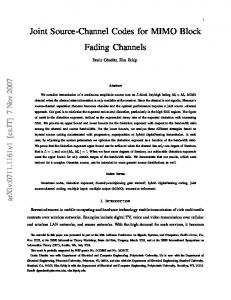
Figure 1. The adopted Multiple Description scheme.
3 Cross-layer optimization of FEC channel coder and MDC scheme As Fig. 1 shows, the orchestration of the whole CL architecture is performed by the CL control unit, which selects the source coding technique (either SD+FEC or MDC), assigns the target bit rates to the source and channel coders, and chooses the ACs at MAC layer. At the beginning of each GOP, the optimization algorithm estimates the crossing point BERX , where the curves of PSNR vs. BER for SD+FEC and MDC intersect. For BER values higher than BERX , the MDC option gives a better quality at the same coding rate, while the SD+FEC
R =1536 kbit/s
R =1536 kbit/s
b
b
33
38 37
BER
X
32
36
PSNR (dB)
PSNR (dB)
tra (I-type) frames are mapped to the Access Category with the highest priority (i.e. AC3), while the packets of Inter (Ptype) frames are mapped to AC2 (see [1] for more details). In case the MDC configuration is adopted, Inter coded packets are sent to AC2 or AC1 depending on whether they belong to description 1 or 2. The physical layer (PHY) of the transmitting station reports the transmission power at the antenna to the CL control unit. In a similar way, the PHY module of the receiver communicates the power of the received signal to the CL unit of the station, which will report this measure to the transmitter via control packets. Hence, the transmitter will be able to compute a Bit Error Rate (BER) estimate of the last transmission session. According to this value, the CL control unit sets the coding parameters and chooses the most appropriate protection strategy, as it will be presented in the next section.
35 34 33 32
−4
10
BER
(a) crew CIF
X
30 29 28
MDC SD+FEC
BER
31
27
MDC SD+FEC −4
10
BER
(b) tempete CIF
Figure 2. PSNR vs. BER for the SD+FEC and MDC configuration. The graphs also show the crossing point BERX which varies according to the transmitted sequence (coded at the same bit rate Rb = 1536 kbit/s).
configuration is chosen whenever the estimated BER is lower than BERX . The value of BERX depends on the characteristics of the coded sequence (see Fig. 2) and on the number of FEC packets added by the SD+FEC scheme. The following subsections will provide further details about the adopted estimation methods.
3.1
The LBG-based estimation of BERX
The robustness of SD+FEC and MDC schemes is strictly related to the spatial and temporal correlations existing in the original video sequence. Since the FEC coder permits recovering the lost information in case the number of lost packets is lower than a given threshold, at high BER values
the FEC code proves to be ineffective and the lost parts of the current frame have to be estimated from the previous ones exploiting the temporal correlation. The MDC coding permits estimating the lost information from the correctlyreceived descriptions, and therefore, at high loss percentages the quality degradation results lower with respect to the SD+FEC coder. Whenever the temporal correlation among adjacent frames is lower than the spatial one, a better concealment can be obtained using the MDC configuration for small BER values too. As an example, the graph related to the sequence crew in Fig. 2(a) shows that the crossing point BERX is smaller than the one for the tempete sequence (see Fig. 2(b)). In fact, the crew sequence presents a low temporal correlation, and therefore, the spatial correlation involved in the MDC error concealment proves to be more effective in estimating the lost information for smaller BER values with respect to the sequence tempete. On the other hand, the strong temporal correlation between adjacent frames of the sequence tempete allows the SD error concealment unit to effectively estimate the lost information at higher BER values. As a consequence, we need a metric to measure the level of spatial and temporal correlation. In the literature, a widely-used parameter to characterize the residual signal energy after a prediction is the Sum of Absolute Differences (SAD), which characterizes the correlation between the original signal and the predicted one. In our scheme, we considered two SAD metrics Nx −1,Ny −1
difft
=
1 Nx Ny
X
|Ii (x, y) − Ii−1 (x, y)|
x,y=0 Nx /2−1,Ny −1
diffx
=
2 Nx Ny
X
|Ii (2 x, y) − Ii (2 x + 1, y)| ,
x,y=0
(1) where Nx , Ny are the number of rows and columns for each frame respectively, and Ii (x, y) is the luminance pixel value of the i-th frame at position (x, y). Before coding, a whole GOP is stored in memory, and the average values E[difft ] and E[diffx ] are computed from the buffered frames and included in an array diff = (E[difft ], E[diffx ]). The array diff is then classified by means of an LBG vector quantizer [2] into one of 16 classes, each corresponding to a different crossing point BERX . This procedure allows to select the most appropriate coding configuration considering the obtained BERX and the measured BER value provided by the PHY layers. The classes have been created from an extensive set of training sequences in order to tune the classifier using a significantly heterogeneous amount of data (further details about LBG classification are given in Section 4) One of the disadvantages of this method is the need of buffering a whole GOP, which implies some delay that
could be unsuitable for interactive applications. It is possible to overcome this problem by computing difft and diffx on the previously coded data or storing a limited number of frames.
3.2
The ρ-based optimization algorithm
The previous section has presented an optimization method that is based on a vector quantization and implies some playout delay at the decoder. In this section, we present an alternative strategy for coding mode selection. Previous works have shown that for SD-based video coders the distortion produced by the loss of a single packet strongly depends on the characteristics of the coded information. In [11] Qu et al. propose an Unequal Error Protection (UEP) strategy that increases the number of FEC packets according to the activity level of the original sequence. In [9], the authors parameterize the distortion produced by the loss of one packet as a function of the percentage ρ of null quantized transform coefficients (called zeros). It is possible to find a similar relation for MDC schemes too. Given the relative PSNR decrement δPSNRl,i =
PSNRi − PSNRl,i , PSNRi
(2)
where PSNRi is the PSNR value for the uncorrupted coded frame and PSNRl,i is the PSNR value of the concealed frame after a loss, it is possible to linearly relate δPSNRl,i with the percentage ρ associated with the information included in the lost packet. The graphs reported in Fig. 3 show that this characterization is possible both for the SD H.264/AVC coder and for the MDC scheme, but the slope and the intersection of the SD line denote a more significant quality decrement for the single description case. This difference is mainly evident for sequences with a strong vertical spatial correlation, which allows the error concealment unit of the MD decoder to accurately estimate the lost information. From Figure 3, it is possible to notice that the quality loss of the MDC scheme is much lower than the quality loss of its SD counterpart for the sequence foreman (see Fig. 3(a)), but in the case of the sequence mobile the adoption of MDC does not permit an improvement of the transmission performance at low ρ values because of the large amount of small details. M The estimated average quality PSNRl for the configuration M (M = SD+FEC or MDC) can be computed as ¡ ¢ M M M PSNRl = (1−pM ρ , (3) loss ) PSNR+ ploss PSNR 1 − kl
where pM loss is the probability of losing a single packet relative to the configuration M , and PSNR and ρ are the average PSNR and ρ values estimated for the GOP to be coded.2 In 2 More
precisely, the coding mode decision algorithm estimates the av-
The following section will provide further details about the adopted bit allocation strategy.
0.4
δ PSNR
l,i
0.35 0.3 0.25
3.3
0.2
MDC
0.15
A hybrid SD+FEC/MDC rate control algorithm
SD
0.1 0.984 0.986 0.988 0.99 0.992 0.994 0.996 0.998
ρ
i
After the algorithm described in the previous subsection has selected the more appropriate GOP coding setting, the proposed CL scheme needs to implement an accurate rate control algorithm that maximizes the quality of the reconstructed sequence under certain bandwidth constraints.
(a) foreman CIF 0.45
δ PSNR
l,i
0.4 0.35
In case the SD+FEC option has been selected, the CL control unit assigns to the i-th frame of the GOP a target number of bits Ti according to the equation
0.3 0.25 0.2
MDC SD 0.97
0.975
0.98
0.985
ρ
0.99
0.995
i
(b) mobile CIF
Figure 3. δPSNRl,i vs. ρi for SD and MDC. this estimation the adopted parametric model relies on parameter values estimated from the coding results of the previous GOP, and therefore, no frame buffering is needed The parameter klM is estimated from a set of training sequences and depends on the coding mode M . The loss probabilities can be expressed as p
SD+FEC loss
= ploss −
n−1 Xµ c=0
¶ Np − 1 c+1 ploss (1 − ploss )Np −1−c c
pMDC = 2 ploss (1 − ploss ), loss (4) where ploss is the packet loss probability estimated from the BER value and the average packet length. The parameter Np is the total number of video and FEC packets for a single frame in the SD+FEC configuration. Note that for the MDC configuration we assume that, in case a packet is lost, the corresponding packet in the other description has been correctly received since the probability of losing both packets is small. SD+FEC value is greater than In case the computed PSNRl MDC the PSNRl value, the CL control unit assumes that the BERX point for the current sequence is higher than the current BER value, and therefore, the SD+FEC configuration is selected. Otherwise, the CL unit employs the MDC scheme. erage target number T of bits available for the Inter frames of the current GOP and associates to T the average target values PSNR and ρ according to the equations reported in Section 3.3.
Ti =
KI,P G NP
G KI,P NI + NP
for an Intra frame for an Inter frame
(5) where the Nt , t = I, P , is the number of t-type frames in the GOP that are still to be coded, KI,P is a complexity ratio between I-type frames and P-type frames (see [8] for more details). The parameter G denotes the number of bits available in the current GOP, which is updated at the beginning of each GOP via the equation
G ←G+
Rb N Fr
(6)
where Rb is the target bit rate, N is the number of frames in the GOP, and Fr is the frame rate. After coding each frame or field, the number of available bits G is updated. In a second step, the CL unit partitions Ti into TiS = Ti /(1 + r) and TiC = r TiS , where r is the coding rate for the FEC coder (i.e. r = n/(Nc − n)). The target value TiS is then associated to a Quantization Parameter (QP) value adopting the algorithm reported in [8] (omitted here for the sake of conciseness), while the channel coding rate r is converted into the number of columns n for the FEC coder. In case the CL control unit chooses to adopt the MDC configuration, an analogous rate allocation algorithm is employed keeping separate frame counters, complexity parameters and ratios for each description. However, in this case, the whole target bit number is assigned to the video source coder since no redundant FEC packets are added. For the MDC configuration, the rate allocation algorithm assigns to the i-th frame of description MDd (d = 1, 2) the
R =1024 kbit/s
R =1536 kbit/s b
38
36
37
PSNR (dB)
PSNR (dB)
b
37
35 34 33 32 31 30
MDC SD+FEC CL LBG CL ρ−based
36 35 34 33 32
MDC SD+FEC CL LBG CL ρ−based
−4
−4
10
10
BER
BER
(a) foreman CIF
(b) crew CIF
R =1536 kbit/s
R =1536 kbit/s
b
b
33 32
PSNR (dB)
PSNR (dB)
32 31 30 29 28 27
MDC SD+FEC CL LBG CL ρ−based
31 30 29 28
MDC SD+FEC CL LBG CL ρ−based
−4
−4
10
10
BER
BER
(c) tempete CIF
(d) coastguard CIF
Figure 5. Comparison between the performance of the schemes SD+FEC, MDC and the CL optimization algorithms LBG-based and ρ-based. The plots report the PSNR values vs. BER obtained from an average of 10 trials per point. target number of bits TiMDd according to the equation MDd KI,P G MD1 MD1 MD2 MD2 MD1 KI,P NI + KI,P NI + KP,P NPMD1 + NPMD2 for Intra frames TiMDd = MDd KP,P G for Inter frames, MD1 MD1 KP,P NP + NPMD2 (7) where the NtMDd , t = I, P and d = 1, 2, is the number of t-type frames of description MDd in the GOP that are MDd still to be coded, Kt,P is a complexity ratio between t-type frames of description MDd and P-type frames of description MD2 MD2 (KP,P = 1). Given TiMDd , the CL unit computes a target QP value for the i-th frame of the MDd description in an analogous way with respect to the SD approach. After coding the current MD frames, the number G of remaining bits in the GOP is updated, and the following frames are processed.
4 Experimental results The CL optimization algorithm was tested with an IEEE 802.11e module built using the Omnet++ simulator [1],
Parameter
Value
AC0 (CWmin , CWmax , RL) AC1 (CWmin , CWmax , RL)
(31, 1023, 4) (31, 1023, 4)
AC2 (CWmin , CWmax , RL)
(15, 31, 8)
AC3 (CWmin , CWmax , RL) Bit rate
(7, 15, 8) 11 Mbit/s
Mobile speed
5 m/s
Path loss α Transmission power
[2.0, 2.3] 75 mW
Figure 4. The adopted network scenario.
and considering a wide set of different sequences. In the training phase of the LBG classifier we used the sequences foreman, news, bus, mobile, city, football, table, soccer, paris, while in the test phase we also adopted tempete and crew sequences in addition. We simulated the transmission of 120 frames coded in GOPs of 15 frames with IPP...P structure. The target bit rate Rb was obtained including in the CL unit a modified version of the rate control algorithm in [9]. The network setting, whose details are reported in Fig. 4, was chosen in order to obtain error rates around the crossing point BERX since the aim of the proposed approaches is to detect the best coding mode
between SD+FEC and MDC. The channel distortion was measured averaging the PSNR value of the reconstructed sequence and the corresponding BER over 10 trials. Experimental results show that the LBG-based algorithm performs very well on both training and test sequences. The experimental results reported in Fig. 5 show that the optimization algorithm is able to obtain the best PSNR value between the MDC and the SD+FEC configurations. Moreover, the PSNR value is about 0.5 ÷ 0.6 dB better than the higher PSNR between MDC and SD+FEC for BER values close to the crossing point BERX (see Fig. 5(a)). In this case, the optimization algorithm is able to switch from one configuration to the other according to the characteristics of the coded video sequence. The performances of the LBG-based CL algorithm and of the ρ-based algorithm are quite similar since the differences between the two approaches (see Fig. 5(b) and 5(a)) are negligible. However, the average PSNR value for the ρ-based approach can be significantly improved by a more accurate estimation of the model parameters (such as klM ). The experimental results reported in Fig. 5 are obtained using a fixed klM obtained from a set of training sequences, and sometimes the adopted model parameters do not accurately suits the characteristics of the transmitted video. As an example, the performance of the ρ-based algorithm slightly decreases for the coastguard and tempete sequences (see Fig. 5(c) at BER=10−4 and Fig. 5(d) at BER=0.5 10−4 ). Better results can be obtained adapting the klM value according to characteristics of the video signal (e.g. using temporal and vertical correlations). In addition, the parameterization introduced with the ρ-based model allows the integration of other optimization and rate allocation techniques (see [9]) which can improve the final performance.
5 Conclusions In this paper we propose a cross-layer control algorithm for a hybrid architecture that combines a classical MDC scheme with a SD coder where some redundant packets are added in order to protect the data stream (SD+FEC). In the optimization strategy the characteristics of the image are extracted and each GOP is adaptively coded using either the MDC option or the SD+FEC one. Two strategies are adopted to select the best mode. The first one is based on a LBG classification of the frames to be coded, while the second one relies on an accurate parametric modelization of the distortion. Both approaches prove to be quite competitive since the resulting PSNR value is always equal or higher (up to 0.6 dB for foreman) than the value provided by the best mode between MDC and SD+FEC. Moreover, the approach based on a parametric modelization of the distortion requires a limited playout delay and allows for the integration of further optimization strategies addressing other
functional blocks in the cross-layer scheme.
References [1] R. Bernardini, M. Durigon, R. Rinaldo, P. Zontone, and A. Vitali. Real-Time Multiple Description Video Streaming Over QoS-Based Wireless Networks. In Proc. of ICIP 2007, San Antonio, TX, USA, Sept. 2007. [2] A. Gersho and R. M. Gray. Vector Quantization and Signal Compression. Kluwer Academic Publisher, Norwell, MA, USA, 1991. [3] B. Girod and N. F¨arber. Feedback-based error control for mobile video transmission. Proc. of the IEEE, 87(10):1707– 1723, Oct. 1999. [4] V. K. Goyal. Multiple Description Coding: Compression Meets The Network. IEEE Signal Processing Mag., 8(5):74–93, Sept. 2001. [5] IEEE 802.11/D13.0, Part 11. Wireless LAN medium access control (MAC) and physical layer (PHY) specifications: Medium access control (MAC) enhancements for Quality of Service (QoS), Jan. 2005. [6] A. K. Katsaggelos, Y. Eisenberg, F. Zhai, R. Berry, and T. N. Pappas. Advances in Efficient Resource Allocation for Packet-Based Real-Time Video Transmission. Proc. IEEE, 93(1):135–147, Jan. 2005. [7] A. Ksentini, M. Naimi, and A. Gu´eroui. Toward an improvement of H.264 video transmission over IEEE 802.11e through a cross-layer architecture. IEEE Commun. Mag., 44(1):107–114, Jan. 2006. [8] S. Milani, L. Celetto, and G. Mian. An Accurate LowComplexity Rate Control Algorithm Based on (ρ, Eq )Domain. IEEE Trans. on CSVT, 18(2):257–262, Feb. 2008. [9] S. Milani, G. A. Mian, and L. Celetto. Joint Optimization of Source-Channel Video Coding Using the H.264 Encoder and FEC Codes. In Proc. of EUSIPCO 2005, Antalya, Turkey, Sept. 2005. [10] J. V. T. J. of ISO/IEC MPEG and ITU-T VCEG. Joint final committee draft (JFCD) of joint video specification (ITUT Rec. H.264 — ISO/IEC 14496-10 AVC). In Joint Video Team, 4th Meeting, Klagenfurt, Germany, July 2002. [11] Q. Qu, Y. Pei, and W. Modestino. An Adaptive MotionBased Unequal Error Protection Approach for Real-Time Video Transport Over Wireless IP Networks. IEEE Trans. on CSVT, 8(5):1033–1044, Oct. 2006. [12] J. Rosenberg and H. Schulzrinne. An RTP Payload Format for Generic Forward Error Correction (RFC2733). Internet Draft, Network Working Group, Dec. 1999. [13] F. Zhai, Y. Eisenberg, T. N. Pappas, R. Berry, and A. K. Katsaggelos. Rate Distortion Optimized Hybrid Error Control for Real-Time Packetized Video Transmission. IEEE Trans. Image Processing, 15(1):40–53, Jan. 2006.