This article has been accepted for publication in a future issue of this journal, but has not been fully edited. Content may change prior to final publication. Citation information: DOI 10.1109/TVT.2017.2725641, IEEE Transactions on Vehicular Technology 1
Cross-layer Power Allocation in Non-Orthogonal Multiple Access Systems for Statistical QoS Provisioning Gang Liu, Member, IEEE, Zheng Ma, Member, IEEE, Xianhao Chen, Zhiguo Ding, Senior Member, IEEE, F. Richard Yu, Senior Member, IEEE, and Pingzhi Fan, Fellow, IEEE
Abstract—Power allocation is a critical issue in the physical layer of power-domain non-orthogonal multiple access (NOMA) systems. However, existing power allocation schemes have not considered the delay quality of service (QoS) requirement in the datalink layer of users, and hence may not ensure the desired delay QoS requested by the services in the upper layers. Different from existing works, we apply the statistical QoS theory into NOMA systems and formulate the physicaldatalink cross-layer power allocation problem as a stochastic optimization problem under different delay QoS constraints. Also, we show that the formulated problem is quasi-concave and propose a bisection-based cross-layer power allocation algorithm. Simulation results show that the proposed algorithm is able to converge to the optimal solution obtained by exhaustive search. Also, the proposed scheme outperforms existing fixed NOMA and TDMA-based schemes in terms of max-min effective capacity. Index Terms—5G, NOMA, power allocation, effective capacity, delay QoS requirement.
I. I NTRODUCTION AND M OTIVATIONS Non-orthogonal multiple access (NOMA) is a promising technology for the 5th generation (5G) cellular networks. Different from conventional orthogonal multiple access (OMA) technologies, signals from different users can be superimposed on the same time-frequency resources via power-domain multiplexing or code-domain multiplexing in NOMA systems [1]. Consequently, higher spectrum efficiency and a larger number of connections can be supported by NOMA technologies. One the one hand, power allocation is a crucial factor that affects the performance of power-domain NOMA systems, and it has attracted a lot of attentions from researchers [2]– [6]. Most of existing works focus on fixed power allocation schemes as in [5]. To improve the quality of service (QoS), the authors in [3] proposed a power allocation scheme to strictly Copyright (c) 2017 IEEE. Personal use of this material is permitted. However, permission to use this material for any other purposes must be obtained from the IEEE by sending a request to
[email protected]. This work is jointly supported by the NSFC (No. 61601377 and No. 61571373) , the Fundamental Research Funds for the Central Universities (No. 2682016CX043), the Key International Cooperation Project of Sichuan Province (No.2017HH0002), and NSFC China-Swedish project (No.6161101297). G. Liu, Z. Ma, X. Chen and P. Fan are with the Key Lab of Information Coding and Transmission, Southwest Jiaotong University, Chengdu, 610031, China. G. Liu is also with the State Key Laboratory of Integrated Services Networks, Xidian University (Corresponding author:
[email protected]). Z. Ding is with the School of Computing and Communications, Lancaster University, Lancaster LA1 4WA, U.K. F. R. Yu is with the Dept. of Systems and Computer Eng., Carleton University, Ottawa, ON, Canada.
guarantee a performance gain over contentional OMA. From a fairness standpoint, a low-complexity polynomial power allocation algorithm was investigated in [6]. In addition, the joint subcarrier and power allocation problem was also studied in [2], [4] with different objectives. One the other hand, delay QoS provisioning has become another important issue for the current and the next generation of wireless networks [7]. For example, delay-sensitive realtime applications, such as voice over IP and video streaming in the current LTE networks, need reliable delay QoS guarantees [8]. Moreover, delay QoS requirements in the next generation wireless networks will be even more stringent [9]. However, the power optimization merely at the physical layer may not lead to the desired delay QoS requirements. As a result, crosslayer design and optimization has become a promising approach to provide delay QoS provisioning in wireless networks [10], [11]. The problem of delay QoS provisioning has been investigated in different wireless networks [7], [8], [12], [13]. Although several works have been done on power allocation in NOMA systems, to the best of our knowledge, the relationship between power allocation in the physical layer and delay QoS requirements in the upper layer has not been investigated. Therefore, how to guarantee delay QoS requirements is also an important design issue in NOMA systems. Motivated by the observations above, we investigate the problem of cross-layer power allocation in power-domain NOMA systems under different delay QoS requirements. More specifically, our proposed power scheme is to jointly design the physical and the datalink layers. Based on the statistical QoS theory in [12], [14], the delay constraint in datalink layer of each NOMA user is characterized by QoS exponent θ, and the max-min effective capacity criterion is adopted as the optimization objective to improve the fairness among different users. Moreover, we show that the formulated cross-layer power allocation problem is quasi-concave, and propose a bisection based power allocation algorithm. Simulation results show that the proposed algorithm is able to converge to the optimal solution of the considered problem. Also, the proposed algorithm outperforms both the NOMA scheme with fixed power allocation in [5] and the TDMA-based OMA scheme in [15]. In addition, when the QoS exponent is large enough, the effective capacity approximates zero. That is to say, NOMA systems cannot guarantee very stringent delay QoS requirements under fading environments, which is similar to the results in conventional wireless networks [12], [14].
0018-9545 (c) 2017 IEEE. Personal use is permitted, but republication/redistribution requires IEEE permission. See http://www.ieee.org/publications_standards/publications/rights/index.html for more information.
This article has been accepted for publication in a future issue of this journal, but has not been fully edited. Content may change prior to final publication. Citation information: DOI 10.1109/TVT.2017.2725641, IEEE Transactions on Vehicular Technology 2
Queue 1
Queue N
AMC
AMC
Power Allocation
Power Allocation
Base Station Delay QoS Exponent (q 1 , q 2 ,..., q N )
Source N
Joint Rate and Power Allocation
Source 1
Superposition Transmission NOMA
B. NOMA Transmission Scheme According to the NOMA scheme [5], the signal ∑transmission √ N at the base station can be represented as n=1 pn sn , where sn and pn are the transmitted signal and the allocated power corresponding to user n, respectively. Hence, the received signal at user sn can be given by yn = hn
N ∑ √ pk sk + wn ,
(1)
k=1
CSI Feedback hn SIC
SIC
Data Sink
Data Sink
User 1
User N
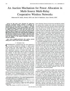
Fig. 1: The cross-layer multi-user downlink transmission model with delay QoS constraints in NOMA systems.
The rest of this paper is organized as follows. The considered system model is described in Section II. The cross-layer power allocation problem is formulated and solved in Section III. The simulation results and conclusions are presented in Section IV and Section V, respectively.
II. S YSTEM M ODEL A. Basic Assumptions As shown in Fig.1, we consider a downlink transmission scenario in NOMA systems with one base station(BS) and N users. All nodes are equipped with a single antenna. The base station transmits the superimposed signal for users using power-domain NOMA scheme [15]. The channel coefficient between the n-th user and the base station is denoted by hn , which follows independent and identically distributed block Rayleigh fading. Without loss of generality, the channel coefficients are sorted as |h1 |2 ≤ ... ≤ |hN |2 . Since block fading is considered, the channel state information (CSI) remains constant in a time slot and varies over time slots. Additive white Gaussian noise with zero mean and unit variance is assumed at the receiver of each user. In addition, the delay constraint in the datalink layer for user n is characterized by delay QoS exponent θn . As described in the effective capacity theory [14], a smaller θn corresponds to a looser delay QoS constraint, and a larger θn means a more stringent delay QoS requirement. Particularly, if θn → 0, it means that the n-th user can tolerate an arbitrarily long delay. On the other hand, if θn → ∞, it means that the n-th user cannot tolerate any delay, which corresponds to the scenarios with an extremely stringent delay-bound. Besides, we also assume each transmission time interval consists of multiple time slots. At the beginning of each transmission time interval, the base station will perform the joint rate and power allocation based on the delay QoS exponent and the feedback CSI for each user.
where wn is the additive noise. At the receiver of each user, successive interference cancellation (SIC) is adopted. Therefore, the n-th user will decode the k-th user’s signal, k < n, and then subtract it from the received signal in a successive manner. The signal for the k-th user, k > n, will be treated as noise at the receiver of n-th user. Consequently, the achievable transmission rate for n-th user, 1 ≤ n ≤ (N − 1), can be written as follows ( ) pn |hn |2 Rn = log2 1 + . (2) ∑N |hn |2 j=n+1 pj + 1 For the N -th user, the achievable transmission rate is RN = log2 (1+pN |hN |2 ). In this letter, we assume that the target rate for each user is equal to the achievable rate Rn , 1 ≤ n ≤ N . Due to the ordering of the channel ( coefficients, it is easy)to verify that the rate Rk→n = log2 1 +
|hn |2
p |h |2 ∑kN n
j=k+1
pj +1
(k ≤
n) for the n-th user to detect the k-th user’s signal is larger or equal to the target rate Rk for the k-th user, i.e., Rk→n ≥ Rk , (k ≤ n), which guarantees the successful implementation of SIC at each user. III. C ROSS - LAYER P OWER A LLOCATION FOR NOMA In this section, the cross-layer power allocation problem for the considered NOMA system will be formulated and solved to maximize the minimum effective capacity for all users. A. Max-Min Effective Capacity Problem Formulation The effective capacity is defined as the maximum constant arrival rate that a given service process can support in order to guarantee a delay QoS requirement specified by θn [12], [14]. According to [12], when block fading is considered, the effective capacity of user n can be given as follows ( [ ]) 1 Ξn (θn ) = − ln E e−θn Rn [t] , (3) θn where Rn [t] is the transmission rate of user n at time t, and it is also the service process for n-th queue at the base station. In another word, Ξn (θn ) is the maximum constant arrival rate for user n with a given service process Rn [t] to satisfy the delay QoS requirement specified by the exponent θn . In addition, the operator E[·] is the expectation with regard to the channel coefficients hn , 1 ≤ n ≤ N . In this letter, in order to provide delay QoS guarantee and to improve the fairness of conventional NOMA, we aim at maximizing the minimum effective capacity for user n. Hence,
0018-9545 (c) 2017 IEEE. Personal use is permitted, but republication/redistribution requires IEEE permission. See http://www.ieee.org/publications_standards/publications/rights/index.html for more information.
This article has been accepted for publication in a future issue of this journal, but has not been fully edited. Content may change prior to final publication. Citation information: DOI 10.1109/TVT.2017.2725641, IEEE Transactions on Vehicular Technology 3
the cross-layer power allocation problem can be formulated as the following stochastic optimization problem { ])} ( [ 1 −θn Rn [t] , (4) max min − ln E e P 1≤n≤N θn N ∑ s.t. C1 : pn ≤ Pmax , n=1
C2 : pn ≥ 0, 1 ≤ n ≤ N, where P = [p1 , p2 , ..., pN ] is the transmit power vector, the constraint C1 is the total transmission power constraint, and Pmax is the maximum transmission power at the base station. In addition, the considered problem is to optimize the transmission power for each user in a transmission time interval, which is consistent with the case of static power allocation with statistical CSI in [13].
Due to the linearity of C1 and C2, it is obviously that all the constraints are convex. To show the quasi-concavity of the objective function is to prove all its superlevel } sets Sα = { ( [ ]) are convex P| min1≤n≤N {− θ1n ln E e−θn Rn [t] } ≥ α for any α ∈ R. That is equivalent to verify the convexity of { [ ] } sets P|E e−θn Rn [t] ≤ e−θn α , 1 ≤ n ≤ N for any α ∈ R. Since −θn Rn [t] is a quasi-convex function with respect to P, then e−θn Rn [t] is also quasi-convex with respect to P according to the composition property of quasi-convex function [16]. [ ] With the help of Theorem 1, we know that E e−θn Rn [t] {is also function with respect to [ a quasi-convex ] } P. Therefore, P|E e−θn Rn [t] ≤ e−θn α , 1 ≤ n ≤ N can be viewed as the intersection of the sublevel set of a series of quasi-convex functions. Hence, all the superlevel sets Sα of the objective function are convex. That is to say, the objective function is quasi-concave and Proposition 1 is proved.
B. Quasi-Concavity of Optimization Problem It is easy to verify that the objective function is neither convex nor concave since there is a linear fractional function in the expression of the transmission rate Rn [t]. Hence, the stochastic optimization problem (4) is also neither convex nor concave. As a result, the optimal solution cannot be obtained directly. Fortunately, it can be shown in the following that the considered problem is quasi-concave. According to the robust optimization problem in [16] (pp. 208-209, Chapter 4), it has been shown that the expectation operator can preserve the convexity. To prove the quasi-concavity of problem (4), we will show that the expectation operator can also preserve the quasi-convexity with the following theorem. Theorem 1: Assume that vector u consists of random variables with a known distribution. If a stochastic function f (x, u) is quasi-convex with respect to variable vector x, then its expectation function1 E[f (x, u)] is also quasi-convex with respect to x. Proof: To prove the quasi-convexity of the function E[f (x, u)], we need to show E{f (θx + (1 − θ)y, u)} ≤ max{E{f (x, u)}, E{f (y, u)}} for any x, y ∈ domf and 0 ≤ θ ≤ 1 according to the definition and basic properties of quasi-convex functions [16]. Since f (x, u) is quasi-convex with respect to variable vector x, then we have f (θx + (1 − θ)y, u) ≤ max{f (x, u), f (y, u)} for any x, y ∈ domf and 0 ≤ θ ≤ 1. Similar to the robust optimization problems in [16] (pp. 208-209, Chapter 4), the inequality is preserved when we take expectations with respect to u on both sides. Hence, we have E{f (θx+(1−θ)y, u)} ≤ max{E{f (x, u)}, E{f (y, u)}}. Therefore, the quasi-convexity of E{f (x, u)} is proved. With the help of Theorem 1, we know that the expectation operator is able to preserve the quasi-convexity. Hence, we have the following proposition. Proposition 1: The stochastic optimization problem (4) is quasi-concave. Proof: According to [16], proving the quasi-concavity of the maximization problem (4) is to verify the quasi-concavity of the objective function and the convexity of the constraints.
C. Cross-layer Power Allocation Algorithm Since the considered problem (4) is quasi-concave, we can transform it into a sequence of convex feasibility problems and obtain its optimum via the following bisection method according to [16]. In each iteration of the bisection algorithm, we only need to solve a convex feasibility problem. At the beginning of the bisection algorithm, we will first initialize the upper bound u and the lower bound l for the objective function. Since the objective function is the maxmin effective capacity of the considered problem and it is not smaller than zero, then the initial lower bound l can be set to zero, i.e., l = 0. Besides, the upper bound can be set to max{Ξn (θn )|pn = Pmax , 1 ≤ n ≤ N }, which is the largest effective capacity when all the power at the BS is allocated to only one of the users. In each iteration, we will compute α = (l + u)/2, and solve the following feasibility problem with a given α. In addition, it is obvious that we have a > 0. Let ζ ∗ > 0 be the optimal value for the objective function of problem (4). In each iteration, for a given α = (l + u)/2, if the following feasibility problem
s.t.
find P [ ] C0 : E e−θn Rn [t] ≤ e−θn α , 1 ≤ n ≤ N, C1 :
1 The
expectation is computed with respect to the random variable vector
pn ≤ Pmax ,
n=1
C2 : pn ≥ 0, 1 ≤ n ≤ N, is feasible, then we have ζ ∗ ≥ α and update the lower bound l for the next iteration to l = α. Conversely, if it is infeasible, then we can conclude ζ ∗ ≤ α and update the upper bound u for the next iteration to u = α. Since all the constraints in problem (5) are convex, hence it is a convex feasibility problem. Equivalently, one can solve the following convex optimization problem min P
u.
N ∑
(5)
s.t.
N ∑
pn ,
(6)
n=1
C0, C2,
0018-9545 (c) 2017 IEEE. Personal use is permitted, but republication/redistribution requires IEEE permission. See http://www.ieee.org/publications_standards/publications/rights/index.html for more information.
This article has been accepted for publication in a future issue of this journal, but has not been fully edited. Content may change prior to final publication. Citation information: DOI 10.1109/TVT.2017.2725641, IEEE Transactions on Vehicular Technology 4
and then check if the power allocation policy satisfies constraint C1. If the optimal power allocation policy satisfies constraint C1, then the problem (5) is feasible; otherwise, the problem (5) is infeasible. Therefore, the optimal solution to problem (4) can be finally obtained using the bisection procedure [16] above, solving a convex optimization problem (6) in each iteration. Since problem (6) is convex, then standard convex optimization can be used to solve it. However, to reduce the computational complexity, we will develop the following customized algorithm to solve problem (6), which distinguishes the proposed algorithm with that in [16]. To this direction, we have the following proposition. Proposition 2: The optimal transmission power [ allocation ] vector P∗ of problem (6) is obtained when E e−θn Rn [t] − e−θn α = 0 and pn > 0 for 1 ≤ n ≤ N . Proof: Firstly, the Lagrangian of problem (6) can be written as follows N N N { [ ] } ∑ ∑ ∑ L= pn + λn E e−θn Rn [t] − e−θn α − ωn pn , n=1
n=1
n=1
(7) where λn and ωn are Lagrange multipliers corresponding to constraints C0 and C2, respectively. For a given 1 ≤ n ≤ N , its optimal solution should satisfy the following KKT conditions [16] which are given by equation (8)-(14). { [ ] } λn E e−θn Rn [t] − e−θn α = 0, (8) [ ] E e−θn Rn [t] − e−θn α ≤ 0, (9) λn ≥ 0,
(10)
ωn pn = 0, pn ≥ 0, ωn ≥ 0.
(11) (12) (13)
It is noted that Ph (h) in equation (14) on the top of the next page is the joint probability density function (pdf) of all the channel coefficients hn , 1 ≤ n ≤ N . When n = 1, the middle term of equation (14) is eliminated. According to (9) and (12), we know pn > 0, 1 ≤ n ≤ N because we have α > 0 and θn > 0. Then, we have ωn = 0 due to equation (11). Therefore, we have λn > 0, [1 ≤ n ≤ N] based on equation (14). Consequently, we have E e−θn Rn [t] − e−θn α = 0 according to (8) and (9). Hence, Proposition 1 is proved. With Proposition 1, we know that the optimal power allocation policy of problem (6) is obtained when the effective capacity of each user is equal to the given parameter α in each iteration. Hence, the analytical solution can be given by equation (15) after several simple calculations ( )− lnθn2 pn |hn |2 = e−θn α , (15) E 1+ ∑ N |hn |2 pj + 1 j=n+1
for a given α > 0 and 1 ≤ n ≤ N . From equation (15), we know that the optimal p∗n only depends on the power allocated the users (n + 1, ..., N ) with stronger channel coefficients. Therefore, the optimal power allocation policy and
the objective function value of problem (6) can be computed by allocating power from the strongest to the weakest channel in a successive manner. In addition, when we compute pn for a given n, the power allocation variables pj , j > n have been determined, and the left-hand side of equation (15) is decreasing with pn . Hence, a bisection method can also be used to search the optimal p∗n for problem (6). Based on the analysis above, the proposed bisection cross-layer power allocation algorithm can be summarized as Algorithm 1 as follows. Algorithm 1 Bisection Cross-layer Power Allocation 1: 2: 3: 4: 5:
Given l = 0 and u ≥ ζ ∗ , tolerance ϵ > 0 and P∗ = 0. Repeat Set α = (l + u)/2 and n=N. Repeat Obtain the optimal p∗ by solving {( )− lnθn2 }n 2 pn |hn | E 1 + |h |2 ∑ = e−θn α with N p +1 n
6: 7: 8: 9:
j=n+1
j
bisection search. n := n − 1. Until ∑Nn ≤ 0. If n=1 pn ≤ Pmax , then l := α, P∗ = P; else u := α. Until u − l ≤ ϵ.
In Algorithm 1, parameter ϵ is the desirable accuracy. The initial interval [l, u] is guaranteed to contain the optimal maxmin effective capacity ζ ∗ . On the one hand, since the max-min effective capacity is not smaller than zero, then the initial lower bound l can be set to zero, i.e., l = 0. On the other hand, the upper bound can be set to max{Ξn (θn )|pn = Pmax , 1 ≤ n ≤ N }, which is the largest effective capacity when all the power at the BS is allocated to only one of the users. In each iteration, the interval is divided in two, i.e., bisected. Therefore, exactly ⌈log2 ((u − l)/ϵ)⌉ iterations are required before the algorithm terminates. D. Special Cases 1) When θn = θ, 1 ≤ n ≤ N and θ → 0: In this case, users have very loose delay QoS requirements and can tolerate an arbitrarily long delay. Hence, the optimization problem (4) is equivalent to max min {E [Rn [t]]} , P
s.t.
1≤n≤N
C1 :
N ∑
(16)
pn ≤ Pmax ,
n=1
C2 : pn ≥ 0, 1 ≤ n ≤ N. The insight behind problem (16) is to maximize the minimum ergodic capacity for all the users. It is easy to verify that problem (16) is also quasi-concave and similar methods can be used to solve it. 2) When θn = θ, 1 ≤ n ≤ N and θ → ∞: In this case, users have very stringent delay QoS requirements and cannot tolerate any delay. It can be easy to verify that the effective capacity approximates zero. That is to say, NOMA systems
0018-9545 (c) 2017 IEEE. Personal use is permitted, but republication/redistribution requires IEEE permission. See http://www.ieee.org/publications_standards/publications/rights/index.html for more information.
This article has been accepted for publication in a future issue of this journal, but has not been fully edited. Content may change prior to final publication. Citation information: DOI 10.1109/TVT.2017.2725641, IEEE Transactions on Vehicular Technology 5
n−1 ∑
∂L =1+ λj ∂pn j=1 ∫ −λn h
∫ h
θj |hj | pj ∑N
[
4
ln 2(|hj |2
2 i=j+1 pi + 1) [
1+
|hj |2
pj |hj | ∑N
i=j+1
θn |hn |2 pn |hn |2 1 + ∑ ∑ N N ln 2(|hn |2 i=n+1 pi + 1) |hn |2 i=n+1 pi + 1
]− lnθj2 −1
2
Ph (h)dh
pi + 1
(14)
]− lnθn2 −1 Ph (h)dh − ωn = 0.
3 Max−Min Effective Capacity with Proposed Algorithm Max−Min Effective Capacity with Exhaustive Search
0.5 Max−Min Effective Capacity with Different p
1
2.5
Max−Min Effective Capacity with Different p
2
Max−Min Effective Capacity (bit/s/Hz)
Max−Min Effective Capacity (bit/s/Hz)
0.45 0.4 0.35 0.3 0.25 0.2 0.15
2
1.5
1
0.5
0.1 0.05
0
0
0.2
0.4
0.6
0.8
0
2
4
1
Power (W)
Fig. 2: The existence of the optimal power allocation policy with Pmax = 1W, θ1 = θ2 = 1.
under fading environments cannot support very stringent delay QoS requirements, which is similar to the results in conventional wireless networks [12]. This will also be illustrated by simulation results. IV. S IMULATION R ESULTS AND D ISCUSSIONS In this section, we evaluate the performance of the proposed algorithm under Rayleigh fading environments as in [12]. Being consistent with [12], the channel gain |hn |2 is generated by an exponential distribution with parameter χn = dβ . In addition, d is the distance between users and the base station, β denotes the path loss exponent and we set β = 4 as in [12]. Moreover, the number of user is set to two for convenience, i.e., N = 2. When initializing the proposed bisection-based algorithm, the lower bound l is set to zero since the max-min effective capacity is not smaller than zero. The upper bound u is set to max{Ξn (θn )|pn = Pmax , 1 ≤ n ≤ N }, which is the largest effective capacity when all the power at the BS is allocated to only one of the users. The desirable accuracy ϵ is set to 10−4 . All the following results are obtained by averaging the results from 100 simulation runs. Firstly, we illustrate the feasibility and effectiveness of the proposed algorithm in Fig. 2 and Fig. 3. In Fig. 2, we verify the existence of the optimal power allocation policy. It is shown that there exists an unique optimal max-min effective capacity for problem (4), which verifies the correctness of Proposition 1. In Fig. 3, we evaluate the convergence performance of the proposed bisection-based cross-layer power allocation algorithm. It can be found that the proposed algorithm is able to fast converge to the optimal solution obtained by exhaustive
6 8 10 Number of Iterations
12
14
16
Fig. 3: The convergence performance of the proposed bisection based cross-layer power allocation algorithm with Pmax = 1W, θ1 = θ2 = 1.
3.5
Max−Min Effective Capacity (bit/s/Hz)
0
Max−Min Effective Capacity with Proposed Algorithm Max−Min Effective Capacity with Exhuastive Search Max−Min Effective Capacity with Fixed NOMA Max−Min Effective Capacity with Fixed TDMA
3 2.5 2 1.5 1 0.5 0 −2 10
−1
10
0
10 Total Power Consumption P
max
1
10 (W)
2
10
Fig. 4: The performance comparison of different schemes with different Pmax and θ1 = θ2 = 1.
search. That is to say, the proposed power allocation algorithm is feasible and effective. Secondly, with different transmission power constraint Pmax at the base station and different distance ratio d1 /d2 among users, we compare the performance of the proposed algorithm with a fixed NOMA scheme and a TDMA-based OMA scheme in Fig. 4 and Fig. 5, respectively. In the fixed , 1 ≤ n ≤ N where µ satisfies NOMA scheme, pn = N −n+1 µ ∑N p = P [5]. In the TDMA-based OMA scheme, max n=1 n each user is allocated equal transmission time in each time slot [15]. As can be seen from Fig. 4, the proposed algorithm
0018-9545 (c) 2017 IEEE. Personal use is permitted, but republication/redistribution requires IEEE permission. See http://www.ieee.org/publications_standards/publications/rights/index.html for more information.
This article has been accepted for publication in a future issue of this journal, but has not been fully edited. Content may change prior to final publication. Citation information: DOI 10.1109/TVT.2017.2725641, IEEE Transactions on Vehicular Technology 6
1.6
Max−Min Effective Capacity (bit/s/Hz)
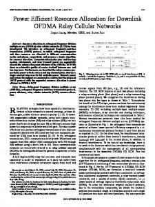
max-min effective capacity approximates zero. It means that NOMA systems under fading environments cannot support very stringent delay QoS requirements, which is similar to the results in conventional wireless networks [12].
Max−Min Effective Capacity with Proposed Algorithm Max−Min Effective Capacity with Fixed NOMA Max−Min Effective Capacity with Fixed TDMA
1.4
1.2
1
0.8
0.6
0.4
0.2
1
1.2
1.4
1.6
1.8
2
The Distance Ratio d1 /d2
Fig. 5: The performance comparison of different schemes with different distance ratio d1 /d2 among users and θ1 = θ2 = 1.
V. C ONCLUSIONS In this letter, the cross-layer power allocation problem in NOMA systems has been investigated for the purpose of statistical QoS provisioning. We showed that the considered max-min effective capacity problem is quasi-concave, and proposed a bisection-based cross-layer power allocation algorithm. Simulation results were presented to show that the proposed algorithm is able to converge to the optimal power allocation policy of the considered problem. Also, the proposed algorithm outperforms the existing fixed NOMA and TDMA-based OMA schemes.
MaxMin Effective Capacity(bit/s/Hz)
R EFERENCES
0.8
0.6
0.4
0.2
0 10000 100
10000 100
1 1
0.01 θ2
0.01 0.0001
0.0001
θ1
Fig. 6: The effect of different delay QoS exponents with Pmax = 1W.
can always converge to the optimal max-min effective capacity obtained by the exhaustive search with different Pmax , which further verifies the effectiveness of the proposed algorithm. Also, as can be observed from both Fig. 4 and Fig. 5, the proposed NOMA scheme outperforms the fixed NOMA and the TDMA-based OMA scheme in terms of max-min effective capacity. This is because the transmission power for each user in the proposed algorithm has been optimized to maximize the minimum of the effective capacity in problem (4). That is to say, better fairness among users can be achieved by the proposed NOMA scheme. In addition, it can be found in Fig. 5, when the distance ratio d1 /d2 increases, the max-min effective capacity will decrease because more transmission power will be allocated to the user with poor channel condition to guarantee the fairness. At last, we also investigate the effect of delay QoS exponent on the max-min effective capacity in Fig. 6. It can be found that the max-min effective capacity decreases with the delay QoS exponent. In another word, a larger effective capacity can be obtained with a looser delay QoS requirement. Inversely, a more stringent delay QoS requirement will lead to a smaller effective capacity. When the QoS exponent is large enough, the
[1] L. Dai, B. Wang, Y. Yuan, S. Han, C.-L. I, and Z. Wang, “Nonorthogonal multiple access for 5G: Solutions, challenges, opportunities,and future research trends,” IEEE Comm. Mag., vol. 53, no. 9, pp. 74–81, Sep. 2015. [2] L. Song, Y. Li, Z. Ding, and H. V. Poor, “Resource management in non-orthogonal multiple access systems: State of the art and research challenges,” to appear in IEEE Network, arXiv:1610.09465, Feb. 2017. [3] Z. Yang, Z. Ding, P. Fan, and N. Al-Dhahir, “A general power allocation scheme to guarantee quality of service in downlink and uplink NOMA systems,” IEEE Trans. Wireless Comm., vol. 15, no. 11, pp. 7244–7257, Nov. 2016. [4] L. Lei, D. Yuan, C. K. Ho, and S. Sun, “Power and channel allocation for non-orthogonal multiple access in 5G systems: Tractability and computation,” IEEE Trans. Wireless Comm., vol. 15, no. 12, pp. 8580– 8594, Oct. 2016. [5] Z. Ding, Z. Yang, P. Fan, and H. V. Poor, “On the performance of non-orthogonal multiple access in 5G systems with randomly deployed users,” IEEE Signal Proc. Letters, vol. 21, no. 12, pp. 1501–1505, Dec. 2014. [6] S. Timotheou and I. Krikidis, “Fairness for non-orthogonal multiple access in 5G systems,” IEEE Signal Proc. Letters, vol. 22, no. 10, pp. 1647–1651, Oct. 2015. [7] W. Cheng, X. Zhang, and H. Zhang, “Statistical-QoS driven energyefficiency optimization over green 5G mobile wireless networks,” IEEE J. Sel. Areas Comm., vol. 34, no. 12, pp. 3092–3107, Dec. 2016. [8] C. Lin, Y. Liu, and M. Tao, “Cross-layer optimization of two-way relaying for statistical QoS guarantees,” IEEE J. Sel. Areas Comm., vol. 31, no. 8, pp. 1583–1596, Aug. 2013. [9] J. G. Andrews, S. Buzzi, W. Choi, S. V. Hanly, A. Lozano, A. C. K. Soong, and J. C. Zhang, “What will 5G be?” IEEE J. Sel. Areas Comm., vol. 32, no. 6, pp. 1065–1082, June 2014. [10] X. Zhang, J. Tang, H.-H. Chen, S. Ci, and M. Guizani, “Cross-layerbased modeling for quality of service guarantees in mobile wireless networks,” IEEE Comm. Mag., vol. 44, no. 1, pp. 100–106, Jan. 2006. [11] X. Lin, N. Shroff, and R. Srikant, “A tutorial on cross-layer optimization in wireless networks,” IEEE J. Sel. Areas Comm., vol. 24, no. 8, pp. 1452–1463, July 2006. [12] J. Tang and X. Zhang, “Cross-layer resource allocation over wireless relay networks for quality of service provisioning,” IEEE J. Sel. Areas Comm., vol. 25, no. 4, pp. 645–656, May 2007. [13] K. T. Phan and T. Le-Ngoc, “Power allocation for buffer-aided fullduplex relaying with imperfect self-interference cancelation and statistical delay constraint,” IEEE Access, vol. 4, pp. 3961–3974, July 2016. [14] D. Wu and R. Negi, “Effective capacity: a wireless link model for support of quality of service,” IEEE Trans. Wireless Comm., vol. 2, no. 4, pp. 630–643, July 2003. [15] A. Benjebbour, Y. Saito, Y. Kishiyama, A. Li, A. Harada, and T. Nakamura, “Concept and practical considerations of non-orthogonal multiple access (NOMA) for future radio access,” in International Symposium on Intelligent Signal Processing and Communications Systems(ISPACS) 2013, Naha, Okinawa, Japan, 2013, pp. 770–774. [16] S. Boyd and L. Vandenberghe, Convex Optimization. Cambridge, U.K.: Cambridge Univ. Press, 2004.
0018-9545 (c) 2017 IEEE. Personal use is permitted, but republication/redistribution requires IEEE permission. See http://www.ieee.org/publications_standards/publications/rights/index.html for more information.