crowds populating virtual worlds, allow for a much more intuitive feeling of shared ..... By developing a protocol dedicated to virtual human animation, it is possible to ... VLNET is based on a client-server architecture [15]. The protocol in VLNET ...
Crowd Modelling in Collaborative Virtual Environments Soraia R. Musse
Christian Babski Tolga Çapin {soraia,babski,capin,thalmann}@lig.di.epfl.ch
Daniel Thalmann
Computer Graphics Lab. Swiss Federal Institute of Technology EPFL, DI-LIG, CH 1015 Lausanne, Switzerland +41 21 6935248
1. ABSTRACT This paper presents a crowd modelling method in Collaborative Virtual Environment (CVE) which aims to create a sense of group presence to provide a more realistic virtual world. An adaptive display is also presented as a key element to optimise the needed information to keep an acceptable frame rate during crowd visualisation. This system has been integrated in the several CVE platforms which will be presented at the end of this paper. 1.1 Keywords Autonomous agents, virtual crowds, virtual environments.
2. INTRODUCTION Virtual humans used as representatives of real participants, or grouped together to form autonomous crowds populating virtual worlds, allow for a much more intuitive feeling of shared 3D worlds. However, they generate a set of problems directly linked to the amount of information that needs to be modelled, transmitted and displayed. In this paper, we consider these problems and their solutions at two different levels: virtual humans in crowd modelling and the CVE platform itself. The first level includes crowd modelling, which aims to provide the sense of group presence through the crowd behavioural animation; and the adaptive display modelling, whose goal is to optimise the information to be shared and displayed in order to maintain an acceptable frame rate of crowd visualisation. The second level includes the presentation of some CVE platforms and the description of virtual humans and crowds integrated [1]. This paper is structured as follows: In section 3, we discuss information concerning the crowd model: group behaviours, crowd control, etc. In section 4 we present the Adaptive Display System. In section 5, we describe the merging with some CVE platforms and results. Finally, section 6 draws some conclusions.
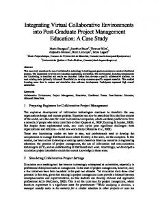
3. CROWD MODEL There are several approaches to model an autonomous crowd, such as particle systems, flocking systems and behavioural systems [14]. These different techniques are characterised by the possible number of individuals to be simulated, their intelligence level and decision ability, the associated collision avoidance method, the employed control method, etc. Particle systems have been used by several authors to provide many autonomous agents controlled by physical rules [4] [5]. Behavioural systems consider the autonomous agent as an intelligent agent which can make decisions using specific rules [13][18] [16]. Flocking systems treat the crowd motion as a flock problem, i.e. animation is specified in terms of distributed global motion, and the individuals seek a goal, can walk together with the others and at the same time they are able to avoid collision [11] [10]. We have defined a crowd as a set of groups formed by human agents. The crowd behaviour is distributed among a number of groups, and the individual behaviours obey this group specification. The crowd motion is based on goals. Each group has a list of goals to follow which is distributed in different ways to the individuals. Our approach to crowd behaviour represents an emergent behaviour, i.e. the global effects which arise as a function of the local rules applied. The data structure of our crowd model is presented in Figure 1. Our crowd model aims at providing a way to populate virtual worlds giving a realistic sense of autonomous group presence. For instance, if we want to have a population of one hundred individuals in a virtual world, we can define a crowd formed by one hundred agents and their crowd behaviour. However, if we could not use the crowd model, we would need one hundred real participants running at the same time and connected together with a network to share the same environment.
Crowd Specifications
Distribution by groups
Groups Specification
Gr i
Gr i+1
Gr i+2
Gr n
There are two types of goals: interest points (IP) and action points (AP). The first one represents a set of points that the crowd must pass through. It is geometrically defined as a position and a region where it is possible to walk. Between two interest points, we can have one or more paths (section 3.2.2). The following figure shows the concept of interest points. IP
Distribution by individuals
Individuals Ag i
Ag .. Ag ..
Ag ..
Region C Region B
Ag ..
IP IP
Specification
Ag .. Ag ..
Ag n
Figure 1: The architecture of the CROWD model.
At a high information level, a crowd is treated as a single entity formed by agent groups who have the following specific behaviours (section 3.2): Seek goal Flocking
group ability to seek specific locations group ability to walk together in a structured group movement Safecollision avoidance between agents wandering and agents with obstacles Following group ability to follow a group or a individual motion Goal change the group behaviour can change as a function of the relationship between individuals Group control group ability to be controlled (can be autonomous or guided - see section 3.2.6.)
Region A
Figure 2: Interest point (IP) information (position + associated region).
The AP has more information than IP. An AP is defined by the position, the region and the specification of whether the agents should stop or not. When the agents must stop on the AP, two additional specifications can be made: vector orientation of the agent and an associated action. In case the agents stop on the AP, the region is used to compute average positions of members of the crowd to reach that AP (section 3.2.2). The action associated must be a keyframe sequence [3] which is a file that includes a recorded posture sequence. After this, the agent goes to the next stimulus (AP or IP).
The simulation of these group’s behaviours is possible if the crowd system knows the simulation environment, in our case, the goals, interests points and obstacles positions. In this case, the system is able to compute the regions over which the group positions must be distributed. In the next sections, we will describe how these group behaviours have been defined and implemented.
3.1 Crowd specification 3.1.1 Environment information In order to simulate a crowd which interacts within a specific environment, it is necessary to know some environment information as well as the connection with the geometrical environment. It aims at providing enough data to the crowd system to be able to avoid collisions, interact with objects, know some specific locations etc. We have classified this information in two different types: the goals (motion stimuli) represent the locations that the crowd must go, pass through, do some action or not, and the obstacle positions, used in collision avoidance.
Figure 3: A keyframe action.
The IP and AP region must be defined to permit implicit collision avoidance with objects. For instance, a path computed using IP/AP regions (such as walking on the sidewalk) can implicitly avoid collision with a building. Figure 4 illustrates the situation.
Agents from the same group share the same list of AP/IP. However, they cannot have the same physical position in space due to collision avoidance. We have considered the region specified through the AP/IP to create positions for each agent.
IP
Figure 4: Implicit collision avoidance with the buildings through the path computed using IP/AP regions.
In this case, we restricted the paths to the surface where the agents can walk (following the IP and AP information). The collision avoidance with objects outside this surface is not considered.
3.1.2 The distribution of crowd information by groups The distribution of IP and AP among the groups which form the crowd presents two different possibilities. The first one is the total control by the user, i.e. the user can choose those goals and interest points which will be the stimuli of a specific group motion. In the second one, the system can perform a simple type of motion planning by using the proximity between goals to decide the next IP. However, the paths always pass through the IP and arrive on a randomly chosen AP. Paths Automatic Reconstruction Begin for each group g final_position = random(list_of_AP) initial_position = random(universe) path=BezierInterpolation(inital_position final_position) for each point pi of Bezier curve for each interest point pj if Near_distance(pi, pj) pi = pj pi_region = pj_region End The initial position for each group can be a random value or be created near a specific AP/IP. After this process, the user can define how many agents must be included in each group of a crowd (this can also be randomly defined) and if a sociological model [11] must be included in the simulation or not. We have specified this sociological model to create some social rules to describe the relationship between the agents (section 3.2.1). In this case, when one agent meets another, a number of social effects can occur and, for example, one agent can follow another one instead of following the group’s specification. The emergent crowd behaviour can change as a function of the above situations meaning that the movement of a crowd can be different.
3.1.3 The distribution of group information by agents
Sub-region 1
Sub-region 2
Sub-region 3
Sub-region 4
Region
Figure 5: Distribution of AP/IP in sub-regions.
The region where the agents can be placed is subdivided in four or more sub-regions depending on the region size. The sub-region to be occupied considers the priority in function of the proximity with the IP/AP and the density of the sub-region. The physical positions inside the subregions are randomly generated for each agent. Individual position generation Begin for each group g for each agent ai from group g sub-region =Priority(current_IP) position_agent ai = Random(sub-region_limits) End This process occurs when the individual paths are computed.
3.2 Crowd Behaviours In this section, some details of behaviours will be described.
the defined crowd
3.2.1 Relationship between individuals There are three possibilities of relationship between the agents in our model: i) two agents can evaluate their positions and decide which one of them must change the path to avoid the collision; ii) one agent can wait for another delayed one, if they are part of a same group and iii) one agent can meet another one and they can evaluate their social parameters according to the social rules defined in the sociological model [11]. In this last case, the group and crowd behaviours can change.
3.2.2 Seek goals behaviour The goals are positions in the universe of the simulation that can be static or dynamic depending on the crowd nature (autonomous or guided) (section 3.2.6). They can be extracted from the environment (static goals), or specified during the simulation (dynamic goals). Each autonomous group has one list of static goals which can be modified only when the sociological model is included. Between two goals or interests points, the path is calculated using the Linear interpolation (eq. 3.2.2.1) or
Bézier Curve (eq. 3.2.2.2) always restricted to a known surface. x = x(t) = (1 − t)a + tb; t ∈ ℜ (eq.3.2.2.1) where a and b define one straight line. r −1
(eq.3.2.2.2)
b i (t) = (1 − t)b i (t) + tb i+1 (t) where r=1,...,n i=0,...,n −r If the Bézier curve has some points outside the surface, this curve can be recalculated to have all the points inside as shown in the Figures 6 and 7. We used the convex hull property of Casteljau Algorithm to prove that the Bézier curve has all points inside the minmax boxes formed by the minimal and maximal co-ordinates of the control polygons [9]. Thus, this minmax boxes must be placed inside the IP region to have a surface constrained. r
r−1
{
3. they follow the paths generated as showed in section 3.2.2; and 4. one agent can wait for another when it arrives on a goal and another agent from the same group is missing. Consequently, the agents from the same group walk together. We considered it as an important characteristic of our model, because in the real life the people also walk in groups. To decide whether one agent must wait or not for another (rule 4), it is necessary to evaluate if all agents from the same group arrived on a specific goal. If not, the agents which already arrived must wait.
3.2.4 Collision avoidance behaviour In a previous work [11] we presented some simple ideas to describe a multiresolution collision avoidance method in which the complexity can change as a function of the camera position. That means, if the camera is far from the agents, the collision method can be simpler than when the camera is near. We have included two different situations in this collision avoidance method. The first one happens when there are not so many individuals at the same time and sharing the same universe region. We called this a low density region. The second case happens when the individuals are in a very populated region, i.e. they are very near to one another. We called that a high density region. Both cases are treated considering two different region sizes for collision detection. Figure 9 shows this process.
Figures 6, 7: Bézier curve constrained to a surface defined by the interest points/goals and distance vectors.
As the agents from the same group share the same list of AP/IP, we computed for each individual one different curve created through the random positions generated, using the goals/IP regions as presented in the section 3.1.3. The paths for the different agents from the same group can be similar but are never the same because they can not occupy the same sub-region, as in Figure 8. IP IP
IP IP
Figure 8: Family of Bézier curves to define the group paths.
3.2.3 Flocking behaviour This behaviour is responsible for flocking formation presented in some group motions in the real world, e.g. flock of birds. In our case, we defined four rules to model the flocking formation. 1. the agents from the same group share the same list of goals; 2. they walk at the same speed;
d
D
d
a)
b)
Figure 9: Examples of high and low density regions.
In case a), there is a high density region, the collision detection occurs only when the individuals are within a distance d to each other. Case b) represents a low density region where the collision is detected within a distance D, greater than d, thus earlier than in the previous case.
3.2.5 The following behaviour This group behaviour provides the possibility to follow one group or agent. In this case we have defined the assumption of group goals which can be permanent or temporary. Let be Group A, a group which follows Group B. If the following motion is permanent, Group A adopts the goals information of Group B until the end of simulation. If this behaviour is temporary, Group A shares the list of goals of Group B at some periods of the simulation, in a randomly defined manner.
3.2.6 Crowd Control
CROWD
There are two different control abstractions for a crowd. The autonomous crowd, formed by autonomous agents which follow the group specification (actions points, interest points, group behaviours, etc.) and the guided crowd; formed by autonomous agents which follow the dynamic goals (section 3.2.6.1). We have used this feature to define one avatar (visual representation of a real participant) which has the control of one or more groups of a crowd, in this case the avatar is considered as a source of dynamic goals. We established a communication betwe en the dynamic goals and the captured positions from the avatar, integrated in a CVE. Figure 10 shows the visual representation of an avatar and three autonomous agents which are following it. More details about the avatar and the connection with CVE platforms in section 5.
Group 1 (guided group)
Figures 10: Three agents following one avatar.
3.2.6.1 Dynamic goals As the crowd motion is always based on goals, we have used the avatar’s position as a source of this type of information. However, this is not exactly the same information as presented in AP/IP (section 3.1.1) because the avatar’s movement is represented just by dynamic positions which change during the simulation. In the next figure we can see a mixed crowd formed by one guided group and one autonomous group. For the guided group one channel is defined and must be shared by our system and by the application, which is in turn responsible for the motion control. For the autonomous group, the IP/AP information must be informed in the beginning of the simulation.
During the simulation
Channel
List of IP List of AP
Application
Group 2 (autonomous)
Begining of simulation
Environment information
List of IP List of AP
Figure 11: The information exchanges for the two nature types of crowd.
4 ADAPTIVE DISPLAY Dealing with virtual humans in shared 3D virtual environments generates some specific problems which are not present for classical objects used in 3D worlds. As long as virtual humans are used to offer a realistic representation for human user, the simulation should not stop at the geometric level. If it is possible to have a realistic human hierarchy (virtual skeleton), we should also be able to use it for realistic animation, thus allowing to use non-verbal communication within those virtual worlds. But such body animation will generate a high amount of information to be sent on the network to permit each connected user to see “who is doing what”. Without optimising this amount of information (at the geometric level as well as the animation level), it will be difficult to have a large amount of people connected without slowing down the frame rate of each connected client (because of the amount of geometric information to display and the amount of information to communicate).
4.1 The Virtual Function By performing a live and constant analysis of the 3D scene in terms of complexity applied to several characteristics such as textures, graphic representation of objects (complexity), deformation and animation, applications should be able to define a global level of detail that will take in account all these parameters. By means of well known methods such as considering the surface of the projection of an object on the front view plane of a user, we can imagine a virtual global level of detail function which could be able to determine the right level of detail for each characteristics according to the effect of one on each other (Figure 12). On the other hand, such a function should not use too many resources. Indeed, it aims at effectively retrieving some CPU power which will be available for keeping a good frame rate. This kind of function should not take into account static objects for which a simple level of detail on
the geometric representation is enough to be efficient. But it can be very useful on animated objects or on an animated group of animated objects : crowds. Texture 10 5 Animation
0
Graph. Rep. LOD 0 LOD 1 LOD 2
Deformation
LOD 3 LOD 4
Figure 12: Global Level of Detail function system.
The parameters of this virtual function are defined at a different level. Some of these parameters, such as geometric level of details, deformation or textures are local to each user. Thus, the optimisation of these parameters will not have a direct effect on network load, but will only permit to keep, locally, an acceptable frame rate. Other parameters like animation have implication on the network load. The finest the animation will be played (ideally 25 frames per second), the highest will be the load of the network, load which will also increase according to the number of participants connected to the shared 3D world. It is one of the reason why we developed this notion of crowd inside the CVEs platform in order to be able to obtain populated world without the need of a lot of users connected. Some specific techniques to reduce the network use are described in the following section.
4.2 Level of Detail Level of details (lods) consist of defining several resolutions of the same logical object, generally from the highest to the lowest resolution. Then, according to a distance or angular parameter, the application is able to switch from one representation to the other, generally in order to avoid having to display information which is not visible anymore. This solution is applied at the level of each participant. It will not avoid network overload but will even participate to it. We have to keep in mind that using lods means multiplying the memory needed to store a logical 3D object by the number of lods. Thus, it increases the time needed to load the entire scene and to send the information to all participants (according to solution adopted by CVEs platforms). This is mainly true for user representation (avatar) which have to be sent to all other participants each time a new user joins the ongoing session but also for notion of private crowd imported inside the shared 3D world by a participant. For our bodies [2], we are able to define five different lods which can be easily included in avatar definition files. But, we have experienced that it is not useful to do so. Indeed,
the only point in including all lods is to obtain a smooth transition from one lod to the other. But as long as switching between lods is generally based on the distance to the view point, it appears to be useless to have so much details : further a given distance, the body is only a few pixels high and users will not even be able to recognise a human body. We conclude that a set of 3 lods is mainly sufficient to obtain an acceptable visual result. We define a high resolution and a low resolution for close and middle range visualisation and, finally, a body reduced to bounding box for long range (Figure 13). Even if this last resolution seems to be a very rough one, its main advantage is that it is still possible to animate it, which permits to keep the ability of a non-verbal communication between users and crowds, even if the distance that separates them is larger than the classically short distance used for communication.
Figure 13 : Highest to lowest resolution for a human body.
Lod 0
Lod 4
Bounding Box
Polygons
20 424
14 646
96
Vertices
61 272
43 938
304
Figure 14 : Polygons -Vertices for different level of details.
The last level of details (bounding box) is of even greater importance for crowds which can involve a non-negligible number of bodies. The lowest level of detail is the billboard. It is formed by a 2D plane which always faces the user. An image representing the body in a given position is mapped on this 2D plane and usually includes an alpha channel to achieve a complete integration with the environment. This mapped image can even be generated in real-time which permits to map an image that corresponds to the actual position of the body and offers to follow the animation of the body even if the body is not represented by a 3D model. Another possibility for billboards is to add notion of angular lod : the mapped picture is depending on the angle between the viewer and the logical object.
Figure 15: Combination of billboard and angular lod methods in DIVE CVE.
4.3 Animation Body animation can generate a high data flow that is likely to overload the network. Applying the notion of level of details and data compression on animation is a good way to minimise network jams 4.3.1 Data Compression at CVEs level With our bodies, we dispose of a set of seventy five joints [2]. In order to achieve credible and natural movements, the different parts of a virtual human body have to be animated constantly, and each transformation will typically generate a network message, i.e. numerous small network messages that are sent very frequently. Animating crowds of virtual humans have even greater implications on band-width since each member of the crowd will be fully animated as described above. CVEs, by performing a specific data aggregation, can optimise network message. Basically, for each segment of a body, an update message will be sent on the network. As described in Figure 16, such a message have to be encapsulated before to be sent, which means as much specific protocol header as body parts to animate. By developing a protocol dedicated to virtual human animation, it is possible to avoid such a duplication of the information for a body animation. Position update messages can be melt in a single message containing all the needed data to display the next frame (Figure 17). This concatenation method can also be applied to a set of virtual humans, typically a crowd, in order to obtain a better optimisation of the size of the needed message. In a crowd, some bodies can stay in the same position, or the same position can be used for several bodies dispersed in the crowd. Protocol Header
1
Protocol Header
Transformation Joint 2
2
...
Transformation Joint 1
Figure 16: Body animation performed by a series of network messages, one for each joint transformation.
The resulting message can even be compressed by using classical methods [17] [12] as long as the increased CPU load for compressing the data is of little significance compared to the reduction in band-width use and transmission time.
Transformation Joint 2 Transformation Joint 3
1234
Protocol Header
...
Transformation Joint 1
Figure 17: Using message aggregation, animating a body from one frame to the next one can result in a single packet.
Such a method supposes that the virtual human body (used for real participant’s representation or for crowds) is not treated as a classical 3D objects to display in the 3D scene. By following standardisation process, like it is made by VRML working group on humanoids [19], a body and his joints can easily be retrieved in the 3D database in order to apply to this object specific optimised methods for animation (see next paragraph) and network communication. 4.3.2 Level of Details on Animation By applying a granularity factor on animation, instead of playing an animation frame by frame and sending associated data through the network to other participants, this animation can be played each X frame. This granularity factor has to be fixed before sending information, which means that each client has to be aware of the network situation. According to some metrics, each application can decide the way they will send their own body animation in order to avoid to charge a link which is already heavily used. Such a system can permit a kind of autoregulation of the network concerning the data linked to body animation.
5 CROWD SYSTEM INTEGRATION The crowd system described in a previous chapter was integrated to several CVE applications. The first one is Virtual Life Network [6] [15] developed jointly by EPFL and University of Geneva; and the second one is DIVE [7] developed by SICS in Sweden. To be able to include crowds model inside several CVEs, independently of the way they were implemented, we developed an autonomous crowd process which is able to connect to CVEs by using their own EAI (External Application Interface) and a specific shared memory segment. This shared memory segment will permit to establish communication between the CVE and the external crowd program.
5.1 Shared Memory System The graph in Figure 18 describes the way UNIX shared memory works. By using a key as an identification of a data structure in the shared memory segment, it is even possible to use several shared memory segments with the same application.
Communication of the identification number from the CVE application to the crowd controller can be done through several different ways : • CVE platform can launch itself the external process; • User can launch manually the external process and • CVE platform and external body controller can use classical socket system (or UNIX signal utilities) to first communicate automatically with each other. 5
Shared Memory Segment Return Id Number
2
3
Link establishment (body process connected to main application)
Shared Memory Allocation
4 CVE Platform
1
Communicate the Id Number
External Crowd Controller
Loading
Standard Body Definition
Figure 18: Shared Memory System
The shared memory segment is organised in a structure which group all data needed for the communication of virtual humanoid’s animation. The communication system is based on a system of flags to wake up the concerned program when data have to be retrieved and updated.
5.2 VLNET Integration VLNET is based on a client-server architecture [15]. The protocol in VLNET consists of session management, state and event information, and interaction among objects. We use fixed-length PDUs, messages, to communicate different information between the server and the clients. Session management messages typically are used during establishing connection with the server, and negotiating between the client and the server. State messages represent the updates to properties of the objects and participants in the scene. There exists different types of state messages, including: • Move: Contains transformation matrix for the object or the participant’s position, pick or view matrices. • Joints: Contains the joints in the body • Hand joints: contains the hand joints of the body • Face_expression: contains the facial expression value. Note that we use special messages for virtual human figures, which contain joint information rather than transformation matrices for body parts. This decreases the bandwidth requirements from 28 Kbits/second required for transmitting body part transformation matrices, to 6.4 Kbits/second for one body. We have shown that these jointbased messages provide a balanced solution between bandwidth requirements, and encoding and decoding
computations at the sender and receiver sites; and accuracy loss. For VLNET state messages, we use stateless protocol. That is, the data contained in these messages are not dependent on the previous packets, hence the latest message overrides the previous ones. This allows to tolerate data loss, performance differences among machines, latency and time delay. Therefore, we can use UDP communication between clients and the server. In the initial implementation, each client controls a unique virtual human figure. The state of the virtual body is communicated to the remote clients through the joint type messages, and this compressed message is used to update the virtual articulated representation ready to be displayed. However, this is a limiting factor for crowd simulation; a client needs to be able to control more than one body. The architecture for inserting crowds is based on the abstraction that the client representing the crowd animates multiple bodies. When the client containing the crowd joins a virtual world, all the remote clients download the bodies for the crowd, and load them. During the session, for each frame, the VLNET client controlling the crowd sends a joint type message for each body within the crowd. Participant 1
Navigation Interface Body Interface
Body Interface
VLNET Client 1
External Crowd Control
Participant 2
Navigation Interface
Navigation Interface
Body Interface
VLNET Client 2
VLNET Client 3
VLNET Server
Figure 19: Example of an autonomous crowd in VLNET. The crowd simulation program is visualised as a client controlling multiple bodies.
Because VLNET is directly implemented on our libraries [2], there's no need to import and to retrieve bodies from the 3D database like it was done with DIVE (see section 5.3). Bodies are created on request, through libraries calls. When a client connects to an ongoing session, a global description of the body is sent through the network in terms of physical characteristics, textures, etc.
Figure 20: Crowd in VLNET
5.3 DIVE Integration DIVE is based on a peer-to-peer approach with no centralised server, where peers communicate by reliable and non-reliable multicast, based on IP multicast. Conceptually, the shared state can be seen as a memory shared over a network where a set of processes interact by making concurrent accesses to the memory. To obtain much more flexibility for crowd use, there are two ways of inserting crowds inside the DIVE platform : •
by using the world definition file (with other classical 3D objects) loaded at the beginning of a shared session and • by using an additional file, defined by the user, and loaded at any time of an on-going session. It is possible to activate autonomous crowds which will be guided by the definition of some interest points in the 3D world, but also guided crowds which will follow the user who created them. In order to insert virtual bodies inside a classical scene file, the hierarchy of our bodies was converted into the specific file format of the DIVE platform. This means that we are able to retrieve joints definition of the human skeleton and degrees of freedom, which composed each joint, from the DIVE platform, in order to be able to update their values and perform animation. The file is analysed when it is loaded inside the DIVE and information about crowds are retrieved by using a set of rules to define name of 3D objects. It is possible to distinguish a basic 3D object from an agent, part of a guided or an autonomous crowd. The repartition of agents to several crowds and the type of an agent (guided or autonomous) is defined through a set of properties attached to each of them. Using a similar set of rules for names and properties, information about the 3D world like objects to avoid or objects which will define points of interest for an autonomous crowd, DIVE is able to define basic rules which will determine the way crowds will interact with the 3D world. This system can be developed in order to define more specific and intelligent behaviour for agents. It is possible to enhance the knowledge of agents about the surrounding world. If an agent stops in front of a painting, according to the author, the agent can adopt different attitudes. Once the DIVE platform has detected a set of crowds (guided or autonomous), a segment of shared memory is allocated which is local to the user who defined crowds. The external crowd controller is launched and a link to the previously allocated segment is established (Figure 21).
External Crowd Control Shared World
Init. Info. (input) Updating Agents Position (output)
Dive World
Shared Memory Segment
Initialization
Dive Platform At Any Time
Updating Agents Position (output)
Crowd Agents and World Information (input - performed once for each world)
User defined Crowds (Autonomous or guided)
Figure 21: Crowd Mechanism: crowds can be loaded at the beginning of a session or at any time in the on-going session.
Both processes, the DIVE platform and the external process, are then connected and are able to communicate specific information for crowds. This link is local to the user who imported crowds inside the 3D shared worlds, and the communication performed through this link will not increase the load of the classical network uses for DIVE communication (Figure 22). Crowd Controller Shared Memory Link
Dive Platform
Network Connection
Local Host - With Crowd
Network
Network Connection
Dive Platform Shared Memory Link
Network Connection
Dive Platform Local Host
Crowd Controller Local Host - With Crowd
Figure 22: Global Overview of DIVE System including crowd controller.
Figures 23, 24: Museum Simulation inside DIVE CVE.
6. CONCLUSIONS We have addressed in this paper two parts of a problem to simulate crowds in CVEs: The first part concerns the modelling level, meaning the crowd modelling and the adaptive display methods. The second part presented the integration between our crowd system and some specific CVEs: VLNet and DIVE. The main goal of this paper was to describe how this integration was done, considering the presented methods, including transferred data, the integration with avatar, the autonomous groups behaviours, the kinds of possible control, etc. Through these integration with others platforms, we have shown that our crowd system has obtained good results mainly concerning the transferred information because it is completely independent. It is our opinion that several behaviours can be included in the model to provide a more realistic interaction with real participants. We are presently working in this direction.
7. ACKNOWLEDGMENTS The authors are grateful to Dr. Ronan Boulic. The research was sponsored by the Swiss National Research Foundation, the Federal Office of Education and Science in the framework of the European project eRENA [8], FUNDEPE and CAPES - Fundação Coordenação de Aperfeiçoamento de Pessoal de Nível Superior (Brazilian office of Education and Science).
8. REFERENCES [1] Benford, S. D.; Greenhalgh, C. M. and Lloyd, D. “Crowded Collaborative Virtual Environments, Proc. 1997 ACM Conference on Human Factors in Computing Systems (CHI’97), Atlanta, Georgia, US, March 22-27, 1997. [2] Boulic, R; Capin, T.; Huang, Z.; Kalra, P.; Lintermann, B.; Magnenat-Thalmann, N.; Moccozet, L.; Molet, T.; Pandzic, I.; Saar, K.; Schmitt, A.; Shen, J. and Thalmann, D. "The HUMANOID Environment for interactive Animation of Multiple Deformable Human Characters". Proceedings of EUROGRAPHICS'95, p.337-348 (Maastricht, The Netherlands, August 28 september, 1995). [3] Boulic, R.; Huang, Z.; Thalmann. D. “Goal Oriented Design and Correction of Articulated Figure Motion with the TRACK System”. Journal od Computer and Graphics, v.18, n.4, pp. 443-452, Pergamon Press, October 1994. [4] Bouvier, E.; Cohen E.; and Najman. L. "From crowd simulation to airbag deployment: particle systems, a new paradigm of simulation". Journal of Electronic Imaging 6(1), 94-107 (January 1997).
[5] Brogan, D. and Hodgins, J. “Group Behaviors for Systems with Significant Dynamics”. Autonomous Robots, 4, 137-153. 1997. [6] Capin, T.K.; Pandzic, I.S.; Noser, H.; Thalmann, N.; Thalmann, D. "Virtual Human Representation and Communication in VLNET Networked Virtual Environments". IEEE Computer Graphics and Applications, Special Issue on Multimedia Highways, March 1997. [7] DIVE - http://www.sics.se/dive/ [8] eRENA - http://www.nada.kth.se/erena/index.html [9] Farin, G. Curves and Surfaces for Computer Aided Geometric Design - A Practical Guide. 2nd ed. Academic Press inc. 1990. [10] Mataric, M. J. “Learning to Behave Socially, in D. Cliff, P. Husbands, J.-A. Meyer & S.Wilson, eds, From Animals to Animats: International Conference on Simulation of Adaptive Behavior, pp.453-462. [11] Musse, S.R. and Thalmann, D. A Model of Human Crowd Behavior: Group Inter-Relationship and Collision Detection Analysis. Proc Workshop of Computer Animation and Simulation of Eurographics’97, Sept, 1997. Budapest, Hungary. [12] Nelson, M. and Gaily, J.L. “The Data Compression Book”, MIS Press, 1996. [13] Noser, H. Thalmann, D. The Animation of Autonomous Actors Based on Production Rules, Proc. Computer Animatio’96, 1996, Geneva, Switzerland. [14] Parent, R. “Computer Animation: Algorithms and Techniques”,http://www.cis.ohiostate.edu/~parent/O xfordPress.html. [15] Pandzic, I.; Capin, T.; Lee, E.; Magnenat Thalmann, N.; Thalmann, D. A Flexible Architecture for Virtual Humans in Networked. Collaborative Virtual Environments, Proceedings of EUROGRAPHICS '97. (Budapest, Hungary, semptember, 1997). [16] Reynolds, C. Flocks, Herds and Schools: A Distributed Behavioral Model. Proc. SIGGRAPH’87, Computer Graphics, v.21, n.4, July, 1987. [17] Storer, J.A. Data compression: Methods and Theory, Computer Science Press, 1988. [18] Tu, X. and Terzopoulos, D. Artificial Fishes: Physics, Locomotion, Perception, Behavior. Proc. SIGGRAPH’94, Computer Graphics, July, 1994. [19] VRML’97 - http://ece.uwaterloo.ca:80/~h-anim.