TECHNOLOGY. CTE: A METHOD TO COMPRESSION - THEN - ENCRYPTION FOR IMAGES. S Sankar *1, S Nagarajan 2. * Department of IT, Hindustan ...
ISSN: 2277-9655 Impact Factor: 4.116 CODEN: IJESS7
[Sankar* et al., 6(6): June, 2017] IC™ Value: 3.00
IJESRT INTERNATIONAL JOURNAL OF ENGINEERING SCIENCES & RESEARCH TECHNOLOGY CTE: A METHOD TO COMPRESSION - THEN - ENCRYPTION FOR IMAGES *
S Sankar *1, S Nagarajan 2 Department of IT, Hindustan University. Chennai, India
DOI: 10.5281/zenodo.809006 ABSTRACT Compression is important because it helps us to reduce the consumption of expensive resources, such as disk space and cost for using bandwidth. Use of the right compression method and encryption technique yield more compact and secure data that are eligible to transfer over public channel. We introduce an optimal approach to compress and then encrypt images. The proposed method is used to increase the compression ratio for images by segmenting an image into non-overlapping segments called edge and non-edge segments and applying different compression depths for these segments. In an edge segment (a region that contains important information) the compression ratio is reduced to prevent loss of information, whereas in a non-edge segment (a smooth region which does not have important information), a high compression ratio is achieved and for encryption a non linear chaotic map is used. The performance of the proposed system is quantified using the peak signal-to-noise ratio to test the compression ratio and also the encrypted image has huge key space which makes harder for hacker to decrypting it using wrong key. KEYWORDS: Data compression, Scanning Pattern, Image Encode, Linearization, Chaotic Map.
I.
INTRODUCTION
Data compression has important application in the areas of data transmission and data storage. Many data processing applications require storage of large volumes of data, and the number of such applications is constantly increasing as the use of computers extends to new disciplines. At the same time, the proliferation of computer communication networks is resulting in massive transfer of data over communication links. Compressing data to be stored or transmitted reduces storage and/or communication costs. When the amount of data to be transmitted is reduced, the effect is that of increasing the capacity of the communication channel. Similarly, compressing a file to half of its original size is equivalent to doubling the capacity of the storage medium. It may then become feasible to store the data at a higher, thus faster, level of the storage hierarchy and reduce the load on the input/output channels of the computer system. Broadly, compression is classified as lossless and lossy. The lossless technique generates an exact replica of the original data stream during decompression. This technique is used when storing data base records, spread sheets or word processing files. On the other hand lossy compression is preferred for archiving and often for medical imaging, technical drawings, etc. where quality of the data is compromised to an acceptable level. Developing innovative schemes to accomplish effective compression has gained enormous popularity in recent years. A brief review of some recent significant research is presented here. Gupta and Anand [10] introduced algorithm based on adaptive quantization coding (AQC) algorithms. The objective is to reduce bit rate produced by AQC while preserving the image quality. The proposed algorithms used only selected bit planes of those produced by encoder using bit plane selection using threshold (BPST) technique. The bit planes are selected by using an additional processing unit to check the intensity variation of each block according to a predefined threshold. John and Girija[20]proposed novel and high performance architecture for image compression based on representation in the frequency domain. The digitized image is compressed using discrete Hartley transform (DHT), discrete Walsh transform, discrete Fourier transform, and discrete Radon transform and their combinations with DHT. DHT is used as a basic transform because of its http: // www.ijesrt.com© International Journal of Engineering Sciences & Research Technology
[214]
ISSN: 2277-9655 Impact Factor: 4.116 CODEN: IJESS7
[Sankar* et al., 6(6): June, 2017] IC™ Value: 3.00
reversibility, hence other transform kernels can be developed where the architecture is developed using verilog hardware descriptive language and has been tested for still images [11] [14]. Raju et al. [21] presented new approach to image compression based on image demosaicing. In the encoder, a mosaic of primary s is encoded instead of the full image considered as four different channels that are compressed using sub-band transform coders. They proposed to use a transfer based on the DCT for the coded channels. The proposed demosaicing technique employs an optimized transfer in the reconstruction of the red and the blue s to impose higher smoothness in the new space in terms of minimal gradient energy. Douak et al. [5] have proposed a new algorithm for image compression. After a pre-processing step, the DCT transform is applied and followed by an iterative phase including the threshold, the quantization, dequantization, and the inverse DCT. Pixels in an image generally, exhibit a certain amount of correlation with their neighbours. In other words, they are highly redundant. DCT transforms such correlated data into an uncorrelated data with minimum information redundancy since the cosine function comprises an orthogonal basis [25]. This transformation is a lossless for any dimensional data; therefore, the inverse operation of the same reconstructs original data ideally. A multidimensional transform can be derived from consecutive application of onedimensional (1-D) transform in an appropriate direction. Because of energy packing efficiency performance criteria, a two dimensional (2-D) version of DCT is widely used in image processing and analysis in problems of spectral analysis, data compression, and pattern matching and so on. A 2-D DCT is obtained by performing a 1-D DCT on the columns of a matrix and then 1-D DCT on the rows of a matrix [6], [9]. These two operations are interchangeable, for any higher dimensions. The same can also apply for an inverse transformation. The results obtained from 2-D DCT will be in an ordered fashion where the mean value of a matrix, known as dc coefficient is in the upper left (0, 0) of the matrix and small high-frequency values, known as ac coefficients are following it. In general, at first, segmenting the image into several square blocks is performed, and DCT is applied to each block. In practice, the block size N most often equals 8 because a larger block takes a great deal of time to perform DCT calculations, which can produce unreasonable trade off. A 2-D DCT operates on one block at a time in a left-to-right and top-to-bottom manner for JPEG images in general [15]. For a N x N image block sequence D(i, j) with {0 ≤ i, j < N}, it is defined as,
D(i, j) =
1 √2N
N−1 C(i)C(j) ∑N−1 x=0 ∑y=0 P(x, y) Cos [ 1 , √2
C(i), C(j) = { 1,
(2x+1)iπ
(2y+1)jπ
2N
2N
] Cos [
]
for i, j = 0
(1)
(2)
1 ≤ i, j ≤ N − 1
D (i, j) and P (x, y) represents an input pixel. Since DCT is perfectly reversible, the inverse DCT (IDCT) is defined as [11],
P(x, y) =
1 √2N
N−1 ∑N−1 i=0 ∑j=0 C(i)C(j)D(i, j) Cos [
(2x+1)iπ
(2y+1)jπ
2N
2N
] Cos [
]
(3)
When DCT is applied to a square block, it converts highly correlated data set in a relatively independent data set [5] and results a dc coefficient, and a series of ac coefficients of zero values at high frequency and small values at low frequency. Since DCT is a lossless transformation, the function Inverse-DCT (IDCT) results original pixel value [25]. Quantization is the process of approximating the resultant DCT matrix into a small set of values, to determine what information can be discarded safely without a significant loss in visual fidelity [25]. Consequently, that leads to the development of lossy compression [10]. The quantization is performed by using the following equation.
Pquant (x, y) = Round (
P(x,y) ) Q(x,y)
(4)
http: // www.ijesrt.com© International Journal of Engineering Sciences & Research Technology
[215]
ISSN: 2277-9655 Impact Factor: 4.116 CODEN: IJESS7
[Sankar* et al., 6(6): June, 2017] IC™ Value: 3.00
Before encoding dc coefficients directly, a Differential Pulse Code Modulation (DPCM) is performed in order to reduce the further size of it. In which the difference between the successive block dc coefficients is calculated as,
∆DCi = DCi − DCi−1
(5)
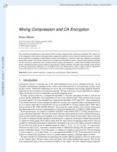
To obtain the best possible compression ratio, the next step is to apply an adaptive scanning [11] providing, for each (n x n) DCT block a corresponding (n x n) vector containing the maximum possible run of zeros at its end. The last step is the application of a modified systematic lossless encoder. In this paper, the proposed method achieves a new image compression ratio because of a scanning pattern called ZZRD, which makes a balance on compression ratio and image quality by compressing the vital portions of the image with high quality. In this approach, the main subject in the image is more significant than the background image. The performance of the proposed scheme is evaluated in terms of the peak signal to noise ratio and the compression ratio attained. The experimental results demonstrate the effectiveness of the proposed scheme in image compression. In the image compression algorithm, the input image is RGB space, and then the image is initially classified into edge and non-edge portions using Canny method [3]. Then the image is subdivided into 8x8 blocks and DCT coefficients are computed for each block. The quantization is performed conferring to a quantization table [8],[9],[10]. The quantized values are then rearranged according to a new scan arrangement as described in next section rather than traditional methods shown in Fig. 1.
Figure. 1 The various methods of DCT coefficient scanning methods: (a) Vertical, (b) Hilbert, (c) Zigzag (d) Horizontal
II.
MATERIALS AND METHODS
Scanning Patterns A scan method can convert a difficult to use signal into an easy to use one by exploring source redundancies within the input signal, which could be very useful in image compression. In Joint Picture Expert Group (JPEG) image compression [22] encoding an image can lead to not an optimum result, if the quantized two-dimensional discrete cosine transform coefficients are not arranged in linear sufficiently. An efficient linearization scheme is necessary to keep highly redundant coefficients consecutively in one dimensional sequence space so that other techniques involved in the compression process can be expected to yield better results. In image compression, particularly JPEG images, exploring the content of an image depends on the way in which it is scanned.
http: // www.ijesrt.com© International Journal of Engineering Sciences & Research Technology
[216]
ISSN: 2277-9655 Impact Factor: 4.116 CODEN: IJESS7
[Sankar* et al., 6(6): June, 2017] IC™ Value: 3.00
Fig. 1. The various methods of DCT coefficient scanning methods: (a) Vertical, (b) Hilbert, (c) Zigzag (d) Horizontal
For an instance, information obtained by scanning the image horizontally differs from those obtained by scanning it vertically [15], [16], [17]. Since there are several ways to scan the image, there are also several possible interpretations of its content. Thus finding the scan that provides more useful and relevant information of the image can be useful for image processing. In the compression context, efficient scanning must be able to explore most redundancy in the image. The JPEG encoder for instance, scans the image block in Zigzag pattern. It is proved that the performance of such encoding depends partly on the way in which the image was scanned. Thus, searching a way to find the most suitable scan may be useful for image compression[19],[20]. In this paper, a novel scanning scheme proposed by S Sankar et.al., 2014 has been implemented for performing linearization where a hybrid procedure is employed by integrating a portion of Zigzag with new Raster Diagonal patterns shown in figure 2 to analyse correlations in the image and strengthen the correlation in the resulting linear pixel sequence, which is easily exploitable for purposes of compression.
Fig. 2. ZigZigRasterDiagonal[25]
Zigzag procedure begins at 1 and ends at 2 and Raster Diagonal begins at 3 and continues till the end of the matrix is reached. The algorithms are applied individually into JPEG Base Line compression process and the performance is analyzed for discrete images with distinguishing factors. The result of quantization process is a 2-D square matrix that holds a dc coefficient and mixed frequency symbols of ac coefficients. Before we start encoding the coefficients, they can be further reduced by applying Differential Pulse Code Modulation (DPCM) method for dc and Run Length Encode (RLE) for ac coefficients respectively. RLE always expects a high http: // www.ijesrt.com© International Journal of Engineering Sciences & Research Technology
[217]
ISSN: 2277-9655 Impact Factor: 4.116 CODEN: IJESS7
[Sankar* et al., 6(6): June, 2017] IC™ Value: 3.00
frequency[24] of the same symbol in a consecutive manner so that it can be replaced by a low frequency symbol, if so, the encoder will produce a smaller number of bits otherwise not. As a fact of this, a better scanning pattern is required to gather high frequency of symbols in places where assorted symbols are presented. Therefore, the scanning pattern only determines the order in which the ac coefficients should be considered to facilitate the encoding process on them. ZigZagRasterDiagonal Pattern In which, a 2-D square matrix is split into exactly two halves diagonally, and the upper left part is scanned in Zigzag fashion, and the lower right part is in a RasterDiagonal fashion as shown in figure 2b. The Zigzag pattern scans ((n*n) /2) + (n/2)-1 number of matrix locations whereas RasterDiagonal pattern scans ((n*n) /2) - (n/2)+1 amount locations where n is the total number of the rows or columns of a square matrix. The algorithm for the ZigzagRasterDiagonal is given below. AlgorithmZigzagRasterDiagonal Input: Q[][]: 2-D array, n: is the total number of rows or columns of a square matrix Output: A[]: 1-D array row ← col ← 1 i←t←0 N← n*n A[] ← a new 1-D array of size N while i is less than N do A[i] ← Q[row – 1] [col – 1] if i < [(N/2)+(n/2)-1] then if [(row + col) & 1 == 0] then if col < n then col++ else row += 2 if row > 1 then row-else if row < n then row++ else col += 2 if col > 1 then col-else if row < n then row++, col-elset ← col + 1, col ← row, row ← t i++ end while return A Step 0: Initialize i=1. Step 1: Follow the procedure Zigzag until to reach the bottom most left cell. Step 2: Move to top right by assigning incremented column value to row and old row value to the column. Step 3: Move to the bottom once by incrementing row by 1and decrementing column by 1 until to reach the bottom side. Step 4: Repeat step 2 and 3 until to reach the last cell. Compression at different depths The proposed compression algorithm named as Depth 4 (D4). We evaluate the efficiency of compression by evaluating the Peak Signal to Noise Ratio (PSNR). Images of different sizes (512x512 and 256x256) are considered in the experiment, most of which are commonly used in the evaluation of computer vision and image processing algorithms. Depth 1 (D1): Without classifying the image as edge and non-edge, all AC coefficients of the edge blocks and non-edge blocks on each component (RGB space) are used for compression. Depth2 (D2): All AC coefficients of the edge blocks on each component (RGB space) are used. After quantization and new scan the non-zero of the quantized coefficients is counted and all AC coefficients will be used as the input of the Huffman coding. The non-edge block will be coded using only the DC coefficient. Depth 3 (D3): In this method, we tried to reduce the number of AC coefficients used in coding the edge blocks. This will reduce the effect of image noise, increase the compression ratio, and accelerate the coding process, which only the quantized DC coefficient value will be used for non edge blocks. http: // www.ijesrt.com© International Journal of Engineering Sciences & Research Technology
[218]
ISSN: 2277-9655 Impact Factor: 4.116 CODEN: IJESS7
[Sankar* et al., 6(6): June, 2017] IC™ Value: 3.00
Depth 4 (D4): a 50% (chosen experimentally) of the non- zero AC coefficients of the edge blocks on R component, 50% of the non-zero AC coefficients of the edge blocks on G component, and 50% of the non-zero AC coefficients of the edge blocks on B component are used. After quantization the non-zero quantized coefficients are counted and only the first 50% of the non-zero AC coefficients on each component (R, G, and B component) is used as the input for Huffman coding. In case of non-edge blocks, only DC coefficients are taken into consideration for encoding. Non Linear Chaotic Map (NCP) In the context of Information Science, data compression is called as source coding where encoding done at the source of the data before it is stored or transmitted and decoding is done at the destination of the data. When it is desired to transmit redundant data over an insecure and bandwidth constrained channel, it is customary to first compress the data and then encrypt it. Compression always relies on high redundant data in order to gain size reduction. Since encryption destroys redundancy, the compression algorithm would not be able to give much size reduction, if it is applied on encrypted data. Compression schemes work by finding patterns in input data that can be destroyed during the encryption which increases compression times. Compressed data can vary considerably for small changes in the source data, therefore making it very difficult to perform differential cryptanalysis on compressed data. For these reasons, we preferred to perform compression before encryption. The image encryption algorithm used in this study is based on the proposed NCA map. It uses chaotic sequence generated by NCA map to encrypt image data with different keys for different images. Original chaotic sequence {x0,x1,x2, . . .} consists of decimal fractions. However images are all digital. So a map is defined to transform the chaotic sequence to another sequence which consists of integers. Then plain-image image can be encrypted by use of XOR operation with the integer sequence .It is depicted in the below figure 3. The encryption steps are as follows: Step 1: Set encryption keys for the plain-image, including structural parameters a, b and initial value x 0. Step 2: Do 100 times of chaotic iteration as formula, and obtain the decimal fraction x 100. Step 3: If the encryption work is finished, then go to step 6; otherwise do three times of chaotic iteration; and as a result, a decimal fraction, such as x103, will be generated, which is a double value and we choose its first 15 significant digits. Step 4: Divide the 15 digits into five integers with each integer consisting of three digits. For each integer, do mod 256 operation, and another 5 bytes of data will be generated. Step 5: Do XOR operation using the 5 bytes of data with 5 bytes of image data (grey value or color RGB value). Step 6: Pass the encrypted image through communication channel.
Figure.3 Steps in NCP
The nonlinear aspect of the algorithm is provided by the use of a power function and a tangent function in the recursive generation of the xn. The formulae used to generate the chaotic matrix are as follows: http: // www.ijesrt.com© International Journal of Engineering Sciences & Research Technology
[219]
ISSN: 2277-9655 Impact Factor: 4.116 CODEN: IJESS7
[Sankar* et al., 6(6): June, 2017] IC™ Value: 3.00 xn+1 = tan(xn) (1 – xn)
(6)
where xn(0, 1) and n = 0, 1, 2, … , and =µ.cot(α/(1+β)).(1+(1/β))
(7)
where = 1 – –4 >0. The ranges of α and β correspond to the chaotic map operating in chaotic regime. This map can apply more large key space than Logistic map.
III.
RESULTS AND DISCUSSION
For edge blocks, some of the non-zero quantized AC coefficients will be eliminated based on its power. As known, the quantization matrix is computed based on the variance of the DCT coefficients. The quantization of a single coefficient in a single block causes the reconstructed image to differ from the original image by an error image proportional to the associated basis function in that block. Moreover, the elimination of some quantized coefficients may give clearly visible errors, i.e., the blockiest of the artifacts distinguishes them from the original image content. We tried to address this problem using two experimental tests. These tests can be summarized as follows. Step 1: For edge blocks the statistical variances of the DCT coefficients will be estimated and the normalized cumulative variance (NCV) of the AC coefficients will be computed. The NCV values are recorded according to the spectral component index. The NCV at the nth spectral component, where n Ε [0, N - 1], is defined as 2 ∑𝑛 𝜎𝑖,𝑗
𝑁𝐶𝑉(𝑛) = ∑
(8)
2 𝑁 𝜎𝑖,𝑗
2 where 𝜎𝑖,𝑗 is the variance of the (I, j) spectral component. Clearly, NCV(n) provides a measure for the percentage of the AC coefficients that can be selected for accepted quality. A set of images with different details has been used to test the NCV(n). On the average, 18% of the DCT coefficients contain about 80% of the total power of the image signal. Step 2: Assume that the edge variance V is the sum of the squared difference for all such pixel pairs
𝑣 = ∑(𝑥1 − 𝑥2)2
(9)
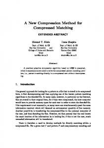
where x1 and x2 are the image values of two pixels that are next to each other in the same row, but are in different blocks. The edge variance is estimated for the original image (Vo) and the reconstructed image (Vr) using the pixels just beside the edge on both sides and taking the average. Experimentally, for (Vr=Vo) > 1.3 the blocking artifact will be clearly visible. A set of images are tested to estimate the minimum number of AC quantized coefficients that give an edge variance less than the critical value with different block size. Related to these two steps, 70% of the nonzero AC coefficients on each component (RGB space) provide good results. After quantization and new scan the non-zero of the quantized coefficients is counted and only the first 70% of the non-zero AC coefficients on each component will be used as the input of the Huffman coding. The non-edge block will be coded using only the DC coefficient. For five test images, the original image and the reconstructed image obtained using the proposed coding schemes are given in Table I. The comparison of performance measures (compression rate measured in bit rate (bpp) and distortion measured in PSNR) of the proposed coding scheme D4 against the results of D1, D2 and D3 coding schemes are presented in Table II which also shows the subjective quality comparison of the different images compressed by different methods (D1, D2, D3 and D4). The best coding results are achieved with the D4 coding scheme based on ZZRD scan [25]. The ZZRD scan has a no effect even the higher complexity of the D4 coding scheme. The time complexity of ZZRD is O (N), where N corresponds to the total number of pixels in the image. The proposed method tested with 1GB of standard test images with varying sizes range from 128x128 to 1024x1024. Figure 4a and 4b show that comparison of PSNR and MSE of proposed method with classical methods. It can be seen that proposed method outperforms with at least 1–2.4 dB for PSNR up to and at least 2.22%of error percentage in average. The difference is much greater at high bit-rate. In fact, it can be seen that depth D1 in the proposed scheme maintains an acceptable PSNR (higher than 3.3 dB) even at a bit-rate as high. A 256 × 256 size 8 bits gallopinghorse.jpg image has been considered as an example for encryption. The encrypted image is depicted in Figure 4. The image is encrypted with initial parameters are =(1.47, 5, 4.876545676545671, 2.3). http: // www.ijesrt.com© International Journal of Engineering Sciences & Research Technology
[220]
ISSN: 2277-9655 Impact Factor: 4.116 CODEN: IJESS7
[Sankar* et al., 6(6): June, 2017] IC™ Value: 3.00 Table 1. Reconstructed images obtained from experiment Test Images
Original
Reconstructed D1
D2
D3
D4
William
Lena
Galloping Horse
Black Hood Lady
45
40
40
35
35
30
30 LZW
25 20
gZip
15 10
MSE (%)
PSNR in db
Prague
25 LZW
20
gZip
15
LZ++
10
5
Proposed method
5
0
0 William
Leena
GallopingHorse
Black Hood Lady
Prague
Image sequence
Image sequence
Figure. 4(a) PSNR (b) MSE
http: // www.ijesrt.com© International Journal of Engineering Sciences & Research Technology
[221]
ISSN: 2277-9655 Impact Factor: 4.116 CODEN: IJESS7
[Sankar* et al., 6(6): June, 2017] IC™ Value: 3.00 Table 2. Comparison of Performance D1 D2
Image William
Lena
Galloping Horse
Black Hood Lady
Prague
D3
D4
MSE
21.82
27.31
30.39
33.42
PSNR
34.82
46.83
54.04
44.22
CR
32.5
44.26
22.81
35.31
bpp
2.22
2.3
1.34
1.81
MSE
11.56
14.87
36.56
47.17
PSNR
12.57
13.8
11.35
21.6
CR
9.72
3.07
9.56
13.47
bpp
1.46
1.8
0.96
1.04
MSE
33.65
46.04
54.41
56.48
PSNR
22.28
32.56
20.78
20.94
CR
10.22
12.09
14.85
10.89
bpp
1.74
3.13
1.18
1.17
MSE
10.84
23.22
34.99
36.81
PSNR
15.55
35.63
22.36
22.49
CR
14.08
16.37
12.26
16.51
bpp
1.15
1.53
0.8
1.71
MSE
12.18
14.39
20.44
21.65
PSNR
27.6
37.82
24.09
14.23
CR
18.05
20.63
17.32
22.04
bpp
0.79
1.19
1.39
1.54
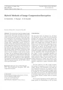
The best coding results are achieved with the D4 coding scheme based on ZZRD scan [25]. The ZZRD scan has a no effect even the higher complexity of the D4 coding scheme. The time complexity of ZZRD is O (N), where N corresponds to the total number of pixels in the image. The proposed method tested with 1GB of standard test images with varying sizes range from 128x128 to 1024x1024. Figure 4a and 4b show that comparison of PSNR and MSE of proposed method with classical methods. It can be seen that proposed method outperforms with at least 1–2.4 dB for PSNR up to and at least 2.22%of error percentage in average. The difference is much greater at high bit-rate. In fact, it can be seen that depth D1 in the proposed scheme maintains an acceptable PSNR (higher than 3.3 dB) even at a bit-rate as high. A 256 × 256 size 8 bits gallopinghorse.jpg image has been considered as an example for encryption. The encrypted image is depicted in Figure 4. The image is encrypted with initial parameters are =(1.47, 5, 4.876545676545671, 2.3).
Figure. 5. a)Compressed Image
b)Encrypted Image
c)Decrypted Image
The secret key should produce a completely different encrypted image. For testing the key sensitivity of the proposed image encryption procedure, we use the wrong key, initial parameters are = (1.47, 5, 4.876545676545672, 2.3). We can note that image still unclear as seen in figure 6.
http: // www.ijesrt.com© International Journal of Engineering Sciences & Research Technology
[222]
ISSN: 2277-9655 Impact Factor: 4.116 CODEN: IJESS7
[Sankar* et al., 6(6): June, 2017] IC™ Value: 3.00
Figure. 6 Decrypted Image with wrong key
For a secure image cipher, the key space should be large enough to make the brute force attack infeasible. The key of the new algorithm consists of three floating-point numbers. If we use the first 20 digits of a floating-point number, then there are 100 uncertain digits are possible. So the possible key space is 2 100. An image cipher with such a long key space is sufficient for reliable practical use.
IV.
CONCLUSION
In this paper, we have implemented a hybrid scan called ZZRD and an image encoding at depth 4 for effectual compression of images an dfor encryption non linear chaotic map is used. The performance of the technique with the recent research is conducted, and shown superior performance of our algorithm in terms of quantitative distortion measures, as well as visual quality and PSNR. The experimental results demonstrate the effectiveness of the proposed scheme in image compression. The encrypted image of compressed image has long key space i.e. 2100 which is good enough to make chaos for the hacker.
V.
REFERENCES
[1] W M Abd-Elhafiez , New approach for color image compression, International Journal of Computer Science vol. 3, pp. 14–9, 2012. [2] Brad Miller, and David Ranum, Problem Solving with Algorithms and Data Structures using Python, Franklin, Beedle and Associates, Chap. 4 – 6, 2011. [3] Canny J., A computational approach to edge detection, IEEE Trans Pattern Anal Mach Intell vol. 8, pp. 679–98, 1986 [4] Debasis Das, and U. A. Lanjewar, Design an Algorithm for Data Compression using Pentaoctagesimal SNS, International Journal of Computer Applications, vol. 62, issue 14, 2013. [5] Douak F, Benzid R, and Benoudjit N, Color image compression algorithm based on the DCT transform combined to an adaptive block scanning, Int J Electron Commun vol. 65, pp. 16–26, 2011. [6] Edmund Y. Lam, Joseph W. Goodman, A Mathematical Analysis of the DCT Coefficient Distributions for Images, IEEE Transactions on Image Processing, vol. 9, issue 10, 2000. [7] Harvey A. Cohen, Deterministic Scanning and Hybrid Algorithms for Fast Decoding of IFS Encoded Image Sets, Proceedings IEEE International Conference on Acoustics, Speech, and Signal Processing, vol. 3, pp. 509-512, 1992. [8] Gao G, Xiong K, and Shang L, Bit-plane image coding scheme based on compressed sensing, Appl Math InfSci vol. 6, pp. 721–7, 2012. [9] Gonzalez RC, and Woods RE, Digital Image Processing, Pearson Edition, 2013. [10] Gupta M, and Anand R, Color image compression using set of selected bit planes, Int J Electron CommTech vol. 2, pp. 243–8, 2011. [11] Martisius I, D. Birvinskas, V. Judas, and Z. Tamosevicius, A 2-D DCT Hardware Codec based on Loeffler algorithm, Electronics and Electrical Engineering. – Kaunas: Technologija, issue 7, pp. 47– 50, 2012. [12] Md. Salah Uddin Yusuf, and Mohiuddin Ahmad, A Novel Scanning Scheme for Directional Spatial Prediction of AVS Intra Coding, International Journal of Advanced Research in Electrical, Electronics and Instrumentation Engineering, vol. 2, issue 8, 2013. [13] Mohammed US, and Abd-Elhafiez WM, New Approaches for DCT-Based Image Compression Using Region of Interest, Scheme.Appl Math InfSci issue 5, pp. 29–43, 2011 [14] Plataniotis KN, and Venetsanopoulos AN, Color Image Processing and Applications, SpringerVerlag, Berlin, 2000. [15] MuzhirShaban AL-Ani, and FouadHammadiAwad, JPEG Image Compression Algorithm, International Journal of Advances in Engineering & Technology, ISSN: 22311963, 2013.
http: // www.ijesrt.com© International Journal of Engineering Sciences & Research Technology
[223]
ISSN: 2277-9655 Impact Factor: 4.116 CODEN: IJESS7
[Sankar* et al., 6(6): June, 2017] IC™ Value: 3.00
[16] TarekOuni, Mohamed Abid, Scan Methods and Their Application in Image Compression, International Journal of Signal Processing, Image Processing and Pattern Recognition, Vol. 5, No. 3, 2012. [17] Thomas H. Cormen, Charles E. Leiserson, Ronald L. Rivest, and Clifford Stein, Introduction to Algorithms, MIT publications, Chap. 6, 2010. [18] Viraktamath S. V., Dr. Girish V. Attimarad, Impact of Quantization Matrix on the Performance of JPEG, International Journal of Future Generation Communication and Networking, vol. 4, issue 3, 2011. [19] Walaa M. Abd-Elhafiez, and WajebGharibi, Color Image Compression Algorithm Based on the DCT Blocks, International Journal of Computer Science Issues, vol. 9, issue 4, 2012. [20] John Paul P, and Girija P N, A high performance novel image compression technique using hybrid transform for multimedia applications, Int J Comp Sci NetSecur 11, 119–25, 2011. [21] Raju Y D, Manjula B M, Kumar M A, Rao, A novel method for color image compression using demosicing, Int J EngSci Res vol. 2, pp.436–40, 2011. [22] Wang J, Long F, Chen J, and Yao J, A novel eye localization method based on Log-Gabor transform and integral image, Appl Math InfSci vol. 6, issue 2, pp. 323–9, 2012. [23] Yao Z, and Baozong Y, A hybrid image compression scheme combining block based fractal coding and DCT, Signal Process Image Comm vol. 8, pp.73–8, 1996. [24] Zhang Y, Pu Y-F, Hu J-R, and Zhou J-L, A class of fractional-order variation image in painting models. Appl Math InfSci vol. 6, pp. 299–306, 2012. [25] S Sankar, and S Nagarajan, ZZRD and ZZSW: Novel hybrid scanning paths for squared blocks, International Journal of Applied Engineering, vol. 9, issue 21, pp. 10567-10582, 2014.
CITE AN ARTICLE Sankar, S., & Nagarajan, S. (2017). CTE: A METHOD TO COMPRESSION - THEN ENCRYPTION FOR IMAGES. INTERNATIONAL JOURNAL OF ENGINEERING SCIENCES & RESEARCH TECHNOLOGY, 6(6), 214-224. doi:10.5281/zenodo.809006
http: // www.ijesrt.com© International Journal of Engineering Sciences & Research Technology
[224]