Laser pulse lengths down to 8Ãps full-width-half- height (FWHH) and energies of 0.5ÃmJ have been produced. The CTF operates with a repetition rate of 10ÃHz.
CLIC TEST FACILITY DEVELOPMENTS AND RESULTS R.ÊBossart, H.ÊBraun, F.ÊChautard, M.ÊComunian, J.P.ÊDelahaye, J.C.ÊGodot, I.ÊKamber, J.H.B.ÊMadsen, L.ÊRinolfi, S.ÊSchreiber, G.ÊSuberlucq, I.ÊWilson and W.ÊWuensch, CERN, 1211 Geneva 23, Switzerland INTRODUCTION The objectives of the CLIC Test Facility (CTF) are to study the generation of short intense electron bunches using a laser driven photocathode in an RF gun, to generate 30ÊGHz RF power for high gradient tests of prototype CLIC components, and to test beam position monitors. The performance of the CTF has improved dramatically in the course of the past year and highlights are presented here. The layout of the CTF is shown in Fig.Ê1. The RF gun now has a Cs2 Te photocathode, enabling the use of the fourth harmonic of the YLF laser system (262Ênm). Laser pulse lengths down to 8Êps full-width-halfheight (FWHH) and energies of 0.5ÊmJ have been produced. The CTF operates with a repetition rate of 10ÊHz with either single bunches or trains of up to 48 bunches. Trains are produced by splitting the laser pulse. The RF gun consists of a 1 1/2 cell cavity, a photocathode, a focusing solenoid and a 4 cell booster cavity. The beam exits the gun with a momentum of 4.5ÊMeV/c and is then accelerated up to 92ÊMeV/c by the S-band travelling wave accelerating section. 30ÊGHz power is generated when the beam is passed through the - un-powered - prototype CLIC main linac accelerating section [1]. The power is fed to the second prototype main linac accelerating section and the accelerating gradient produced in it is directly measured by reaccelerating the lead bunch of the drive train. PERFORMANCES In the 1994 run, the CTF produced 30ÊGHz powers of up to 76ÊMW, which corresponds to a peak gradient of 123ÊMV/m in the 30ÊGHz decelerating section and an average gradient of 94ÊMV/m in the 30ÊGHz accelerating section. Consistency between accelerating fields determined through RF power measurement and reacceleration was confirmed up to 76ÊMV/m. There has never been any sign of RF breakdown in either accelerating
section, any 30ÊGHz component or waveguide at any power level achieved so far. In addition, the output periodically loaded waveguide of a prototype transfer structure was tested to 60ÊMW without RF breakdown. These results show that CLIC can be operated at nominal field levels with little or no conditioning. The maximum power achieved in the 1994 CTF run was almost a factor 2 higher than that achieved in the 1993 run [2]. This improvement is mainly due to an increased beam energy of 92ÊMeV which reduces the detrimental effect of long range transverse wakefields in the decelerating section. A second modulator and klystron allowed the generation of the extra 3ÊGHz power. Further improvement came from raising the number of bunches to 48 which increased the charge passing through the decelerating section. This was made possible by an upgrade of the laser pulse train generator. The train generator upgrade has also given the capability to vary the laser pulse lengths. A longer laser pulse length reduces the effect of space charge in the RF gun and has given a single bunch charge at the gun output to 35ÊnC. This charge is more than twice the previous CTF record. The electron bunch length at this charge was σ zÊ = 2.4Êmm and thus further improvement can be expected. The maximum charges achieved in the CTF are summarized in TableÊ1. The single bunch charge is limited by space charge effects in the gun and short range transverse wakefields in the 3ÊGHz structure. Multibunch charge at the RF gun exit is limited by the available laser energy. The downstream charge is further limited by long range transverse wakefields and chromatic effects due to beam-loading in the S-band accelerating structure. The highest 30ÊGHz powers were produced by a 48 bunch train with a total charge of 80ÊnC transmitted through the 30ÊGHz decelerating section. For this charge the measured bunch length was σ zÊ ∪Ê 1 Ê m m which corresponds to the resolution limit of the streak camera.
35MW
35MW
LIPS
11 MeV
92 MeV
CLIC structure
3GHz accelerating structure 3GHz RF gun
bunch compressor train generator
quadrupoles laser
30 GHz power
spectrometer CLIC structure 15 m
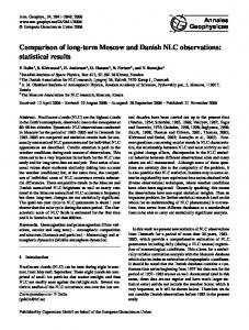
FigureÊ1: Layout of the CTF planned for 1995
A: A phase jump of 180ϒ 1.2ʵs before the end of the RF pulse. This has been the standard mode of operation before the programmable phase shifter was available. RF Gun exit B: A phase jump of +68ϒ 1.2ʵs before the end of the RF 3GHz structure exit pulse, followed by a gradual phase shift from +68ϒ to 30GHz structure exit +180ϒ during the remainder of the pulse. TableÊ1: Maximum measured charges C: A linearly decreasing phase by -30ϒ during the first 3.3ʵs, then 3 a jump of +68ϒ , followed by a linear EMITTANCE MEASUREMENTS phase shift of +112ϒ during 1.2ʵs. Scheme A produced a sharp rise followed by an Emittance measurements were performed with single exponential decay with an overshoot 2.5 times larger than bunches by varying the strengths of two quadrupoles downstream of the 3ÊGHz structure and measuring the beam the average pulse power. Scheme B delivered a nearly flat profiles on a transition radiation screen just upstream of the power pulse with an overshoot of only 20% above the 30ÊGHz accelerating section. The measurement results average power. Nonetheless scheme B provided 10% less together with simulation results from PARMELA are shown acceleration of the beam than method A. This occurred in Fig.Ê2Ê[3]. The normalized, 1Êσ, rms emittance is used.because scheme B introduces a frequency shift of about For these measurements the laser spot on the photocathode 30ÊkHz at the output of the LIPS cavities. This has been had a radius of 5Êmm and a duration of 8Êps FWHH. The compensated in scheme C by the negative phase ramp at phase difference between the zero crossing of the electric the beginning of the RF pulse. The energy gain of the beam field in the gun and the arrival of the laser pulse was 30ϒ. with scheme C is 5% lower than scheme A for constant Although the variation of emittance with bunch charge is klystron power. Because the beam energy was not limited qualitatively similar for measured and computed values, by klystron power but rather RF breakdowns in the 3ÊGHz the measured emittances are systematically higher. This accelerating section the lower overshoot of scheme C is effect is not understood. The large error bars on measured more important. An energy gain of 87ÊMeV was achieved emittances at high charges are caused by unstable beam with scheme C and only 70ÊMeV with scheme A. position in beamline
single bunch [nC] 35 20 7
48 bunches [nC] 450 160 81
conditions. PHOTOCATHODES
180 160 140 PARMELA 120
Measurement
100 80 60 emitt 40 20 0 0
5
10
15
20
25
FigureÊ2: Emittance as a function of bunch charge RF PULSE COMPRESSION The 3ÊGHz accelerating section is powered by a 35ÊMW klystron with a 4.5ʵs long pulse compressed to 1.2ʵs by two LIPS cavities as shown in Fig.Ê1. This type of pulse compression requires a phase shift near the end of the klystron output pulse [4]. Using a new programmable 3ÊGHz low level RF phase shifter, three phase shift schemes were tested.
Nine photocathodes have been used in the RF gun during the 1994 CTF run. Four Cs2Te cathodes were used at 100ÊMV/m for a total of 159 days. However, three others worked only at a lower field, 70ÊMV/m, and were used for only a total of 22 days. The typical starting quantum efficiency (QE) was about 5%, measured in a dc gun at 8ÊMV/m. The QE was found to increase with increasing electric field during measurements with the photocathode in the RF gun, see Fig.Ê3. The QE does not show a strictly exponential degradation with time. During a period of 4 to 5 days after installation in the RF gun, a rather fast decay with a 1/e lifetime of approximately 6Êdays is observed, while afterwards the QE decreases more slowly, with the 1/e decay time varying between 34 and 67 days for the next two months (the beam duty factor is typically 30%). Measurements with closely spaced laser pulses have demonstrated that the relaxation time of electrons in the photocathode material is less than a few picoseconds. Two new photocathode materials which can be transported in air, unlike Cs2Te which requires a vacuum transfer system and preparation chamber, were tested. CsI with a thin layer of germanium has a QE of 0.19% at 100ÊMV/m. A magnesium layer on a copper substrate has a QE of only 0.027% for the same electric field.
0.04
4
Cs2Te
3
0.03 0.02
2 Mg
Te 2 C 1
0.01 Mg
0 0
25
50
75
100
23
20
26
20
26
40
0 125
Egun (MV/m)
FigureÊ3: Quantum efficiency versus electric field for Cs2Te and Mg photocathodes.
MODIFICATIONS FOR THE 1995 RUN In order to reduce the beam-loading and transverse wakefields in the 3ÊGHz accelerating section, the old spare LIL section used until now will be replaced by a high gradient, 1 m long structure borrowed from LAL [5]. A magnetic chicane bunch compressor between the RF gun assembly and the accelerating structure will be used in the 1995 run . An energy/phase correlation in a bunch (introduced by appropriate phasing of the booster cavity) together with the energy/path length dependence in the chicane compresses the bunch. The chicane consists of two 15Êcm long left bending magnets and a 30Êcm long right bending magnet [6]. Two quadrupoles upstream of the chicane and four downstream (not shown in Fig.Ê1) are used to match the beam in the transverse plane. In order to increase the high charge performance of CTF, a new RF gun is being constructed. A drawing of the RF geometry is shown in Fig.Ê4, and the main parameters are listed in TableÊ2. The design goals were to maximize aperture to allow a large beam radius, maximise acceleration in the first cell to keep the effect of space charge small, and to minimize the r/Q to minimize energy spread in bunch trains. These goals are achieved with a large iris aperture, a 10ϒ concave cone around the cathode, and re-optimized cell lengths. number of cells iris diameter [mm] cone angle frequency [MHz] output energy [MeV] input power [MW] max. field on photo cath. [MV/m]
3 40 10ϒ 2998.55 6.58 13.6 100
TableÊ2: Parameters of the new RF gun
FigureÊ4: Sketch of the new RF gun (distances in mm)
REFERENCES [1] H. Braun, R. Corsini, J.P. Delahaye, G. Guignard, C.D.ÊJohnson, J.H.B. Madsen, L. Thorndahl, I.ÊWilson, W.ÊWuensch, B.ÊZotter, ÒCLIC - a compact and efficient high energy e + /e - Linear Collider,Ó this conference. [2] R.Bossart, H. Braun, J.P.ÊDelahaye, K.K.ÊGeissler, J.C.ÊGodot, J.H.B.ÊMadsen, A.J.ÊRiche, L.ÊRinolfi, S.ÊSchreiber, S.ÊSladen, G.ÊSuberlucq, I.ÊWilson. W.ÊWuensch, ÒPerformances Obtained with the CERN Linear Collider Test Facility,Ó European Part. Acc. Conf., London, 1994, p. 680-682. [3] M. Comunian, ÒEmittance Measurements in CTF,Ó Tesi per il corso di perfezionamento in Fisica, Universit di Padova, 1995. [4] A. Fiebig and Ch. Schieblich, ÒA SLED Type Pulse Compressor with Rectangular Pulse Shape,Ó European Part. Acc. Conf., Nice, 1990, p. 937-939. [5] G. Bienvenu and P. Brunet, ÒDark Current under Low and High Electric Field,Ó European Part. Acc. Conf., London, 1994, p. 775-777. [6] F. Chautard, ÒLe compresseur de paquets dÕ⁄lectrons pour le banc de test du collisionaire lin⁄aire du CERNÓ, PhD-thesis in preparation, Paris University VI.