Hindawi Publishing Corporation Journal of Nanomaterials Volume 2013, Article ID 619105, 7 pages http://dx.doi.org/10.1155/2013/619105
Research Article Cubic Composite Sensor with Photodiodes for Tracking Solar Orientation Yong-Nong Chang Department of Electrical Engineering, National Formosa University, Yunlin County 63201, Taiwan Correspondence should be addressed to Yong-Nong Chang;
[email protected] Received 26 September 2013; Accepted 10 October 2013 Academic Editor: Liang-Wen Ji Copyright © 2013 Yong-Nong Chang. This is an open access article distributed under the Creative Commons Attribution License, which permits unrestricted use, distribution, and reproduction in any medium, provided the original work is properly cited. A cubic composite solar sensor with photo diode is proposed for tracking the relative solar orientation. The proposed solar sensor composes of five photodiode detectors which are placed on the front, rear, left, right, and horizontal facets in a cubic body, respectively. The solar detectors placed on five facets can detect solar power of different facets. Based on the geometric coordinate transformation principle, the relationship equations of solar light orientation between measured powers with respect to various facets can be conducted. As a result, the solar orientation can be precisely achieved without needing any assistance of electronic compass and extra orientation angle corrector. Eventually, the relative solar light orientation, the elevation angle, and azimuth angle of the solar light can be measured precisely.
1. Introduction Recently, the renewable energy has drawn great attention due to energy shortage. Many renewable energy researches are focused on solar power system [1–4]. For the solar system, a precise sensor is indispensable to tracking the sunlight orientation. Many studies have been focusing on solar tracking technique. However, there still exist some drawbacks on solar light tracking apparatus. Solar light tracker can, in general, be classified into mechanical and electronic category [5, 6]. Mechanical solar tracker experiences much fault probability and maintenance cost, electronic solar tracker depends highly on electronic compass accompanied by perpetual calendar, and precise perpetual calendar heavily relies on complicated computation through the usage of internet, thus leading to inconvenience in application [7, 8]. Therefore, to develop an electronic solar light tracker, without needing electronic compass and perpetual calendar, is essential to researchers and solar power applications. An electronic solar light tracker can only be realized through the application of photo detecting devices. There are many photo devices such as photodiode, photo transistor, and resistive CdS components. The CdS components are passive components and usually cannot play the key role in a precise measurement. In this paper, the active photodiodes with wide
measuring range and fast response and low dark current are applied as a solar sensor to measure the solar orientation. The solar light orientation information should consist of the relative elevation angle and azimuth angle between solar source and photo detector. For collecting lights from all possible orientations, this paper employed five photodiodes to compose a cubic structure photo detector in the absence of electronic compass and perpetual calendar to accomplish an electronic solar light orientation tracking system. The composite sensor is composed of five photo diode detectors placed on five different facets: left, right, front, rear, and horizontal facets, to constitute a cubic structure solar light detector. By placing five detectors on five different facets, the sunlight orientation can be derived by geometric coordinate transformation technique. There exists discrepancy in collecting power amounts for photo detectors on different facets. Moreover, the incident light on the photo diode comprises not only direct solar light but also diffuse light and scattered light [8]. The diffuse and scattered light power is also generally called undisciplined light power, denoted by 𝑃U . Therefore, the received solar power should be categorized precisely into power of direct incident solar light 𝑃D and power of undisciplined incident solar light 𝑃U . Through the geometric transformation analysis and accurate evaluation formula, each collecting solar power
2
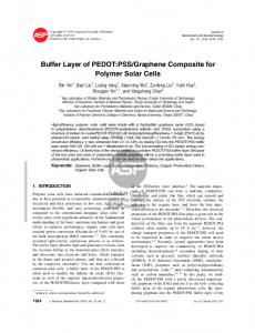
Journal of Nanomaterials 1000
+
900 Vout
800 (W/m2 )
RP
−
Figure 1: Photo diode applied circuit for detecting solar power.
on different facets can be divided into direct incident solar power 𝑃D and undisciplined incident solar power 𝑃U , to accomplish the calculation of solar light orientation and solar polar powers on all facets. In this paper, a novel light orientation sensor is proposed to track the solar orientation effectively. No expensive electronic components and no perpetual calendar are required. By appropriate computation based on different solar power quantities collected from five sensors, the sunlight direction can be determined. Also, the solar light orientation and power can easily be attained.
2. Optimal Shunt Resistor Matching and Selection The ideal photo diode should generate an active current source which is proportional to the incident solar light. The total current through the photodiode is the sum of the dark current and the photo active current, so the dark current must be minimized to maximize the sensitivity of the device. In order to obtain the correct photo voltage, an appropriate shunt resistor 𝑅𝑃 should be shunted across the output terminals. The application circuit is shown in Figure 1 with external shunt resistor 𝑅𝑃 ; the photo voltage is generated at the two ends of the photo diode. The dark current has essential effects on the output voltage. Therefore, a calibration process for the shunt resistor 𝑅𝑃 is required. The values of the output load resistor 𝑅𝑃 . The adopted photo detector in this paper is produced by Hamamatsu Inc. with model code S1087-01. The parameters of the shunt resistor are assorted at 10 Ω, 100 Ω, 220 Ω, 510 Ω, 1 kΩ, and 2 kΩ. The solar power is defined as 𝑃solar , the output voltage is defined as 𝑉out , and 𝑆 is defined as the sensitivity of the detector. In regard to an ideal photo power detector, 𝑆 should be kept with a constant quantity to maintain the linear relationship between sensing power and sensor output voltage as follows. 𝑃Solar =
𝑉out . 𝑆
(1)
By shunting appropriate resistor 𝑅𝑃 in the output terminal, the solar power can be measured as shown in Figure 2, in case that ill condition occurs. The resistor value cannot be used to convert the current into voltage correctly. As shown in Figure 2, during the lower solar power period in the morning
700 600 500 400 300
08:00 09:00 10:00 11:00 12:00 13:00 14:00 15:00 16:00 17:00 Time Standard meter S1087-01 100 Ω S1087-01 220 Ω
S1087-01 510 Ω S1087-01 1 kΩ S1087-01 2 kΩ
Figure 2: Optimal resistor matching and selection.
or evening periods, the solar power is roughly proportional to the photo current with resistor ranging from 100 Ω to 220 Ω. However, the output power is slightly lower than the standard value during midday with direct sunlight. When the value is above 2 kΩ, the solar power curve lies under the standard curve. When the resistor value is between 510 Ω and 1 kΩ, the output curve is inspected to be better fitting the theoretical solar power. Since the photo diode has nonlinear equivalent characteristics as shown in Figure 2, an appropriate output resistor is required to be selected. When the sunlight is in either weak condition or strong condition, the solar power curve displays nonlinear phenomenon. When the value falls between 510Ω∼1 kΩ, the curve has the best coincident condition with the standard curve. Considering that the identical solar power would generate identical output voltage, larger resistance will require less output current. Therefore, 1 kΩ resistor is selected to shunt with photo detector to enhance the linearity and precision of the proposed circuit. In order to obtain the precise voltage conversion, an OPAMP circuit is designed to ensure the precise voltage gain for the five detectors. The calibration circuit of the detector is shown in Figure 3. The 0.01 𝜇F capacitor is connected across shunt resistor 𝑅𝑃 to eliminate noise.
3. Geometric Coordinate Transformation and Formulation As designated in Figure 4, photo-detecting device is located at origin of the horizontal plane of 3D coordinate. The polar coordinate representation of position of light source is designated as (𝑟, 𝜙, 𝛼) which results in the Cartesian
Journal of Nanomaterials
3 Z
R2 50 kΩ R1 100 kΩ
Photo diode
0.01 𝜇F
I
+
0.01 𝜇F
−
𝜃z Vo
𝜃y
R3 1 kΩ
Figure 3: Detector calibration circuit. X
Y
𝜃x
Z
Figure 5: 𝜃 rotation along the 𝑋-, 𝑌-, and 𝑍-axis.
direction, and the normal vector direction of 𝑋-𝑌 horizontal plane is defined as the 𝑍 direction, as indicated in Figure 4. The solar light incident angle 𝜙 can also be defined as the angle between the sunlight and the normal vector direction of horizontal plane. Thus, the horizontal detector collects direct light power 𝑃HD which can be expressed as
(x, y, z)
r
𝑃HD = 𝑃D cos 𝜙. 𝜙 𝜙h
𝛼
Y XY
Horizontal detector
x
y
X
Figure 4: Geometric coordinate system.
coordinate and polar coordinate transformation relationship expressed as follows: 𝑥 = 𝑟 sin 𝜙 cos 𝛼, 𝑦 = 𝑟 sin 𝜙 sin 𝛼,
(2)
𝑧 = 𝑟 cos 𝜙, where 𝜙 is the light incident angle, 𝛼 is the azimuth angle, and 𝑟 is the distance between light source and photo diode detector. Then, the elevation angle 𝜙ℎ can be described as 𝜙ℎ = 90∘ − 𝜙.
(3)
The orientation of sunlight is defined as elevation angle 𝜙ℎ and azimuth angle 𝛼 that means the orientation of the sunlight can be specified by formulation using the two angles: 𝜙ℎ and 𝛼. For a 3D coordinate system, the rear direction is defined as the 𝑋 direction, the right direction is defined as the 𝑌
(4)
The collected direct light power 𝑃HD of horizontal detector is the multiplication of solar direct radiation power and cosine of incident angle 𝜙. Incident angle 𝜙 is defined as the angle between the normal vector of each facet with its corresponding incident light. Thus, when the horizontal detector rotates an angle 𝜃 along 𝑋, 𝑌, and 𝑍 axis, the associated incident angles of all facets will change accordingly. Figure 5 illustrates the rotational coordinate transformation by rotating along 𝑍-axis with an angle 𝜃𝑍 or along X-axis with 𝜃𝑥 or along 𝑌-axis with 𝜃𝑦 . By doing so, the original coordinate (𝑥, 𝑦, 𝑧) is transformed to a new coordinate (𝑥1, 𝑦1, 𝑧1), and the expression can be written as follows. (1) By rotating 𝜃𝑧 along 𝑧-axis, 𝑥1, 𝑦1, and 𝑧1 can be obtained as follows 𝑥1 𝑥 cos 𝜃𝑧 − sin 𝜃𝑧 0 [𝑦1] = [ sin 𝜃𝑧 cos 𝜃𝑧 0] [𝑦] 0 1] [ 𝑧 ] [ 𝑧1 ] [ 0 sin 𝜙 cos 𝛼 cos 𝜃𝑧 − sin 𝜙 sin 𝛼 sin 𝜃𝑧 = 𝑟 [ sin 𝜙 cos 𝛼 sin 𝜃𝑧 + sin 𝜙 sin 𝛼 cos 𝜃𝑧 ] . ] [ cos 𝜙
(5)
In (5), new coordinate 𝑧1 is identical with the original coordinate 𝑧. The angle between incident solar light and normal vector of detector plane of new coordinate still remains 𝜙; the projection on normal vector direction is 𝑟 cos 𝜙. Therefore, regardless of the rotating angle 𝜃𝑧 , the incident of solar light keeps unchanged, that is, 𝜙.
4
Journal of Nanomaterials (2) By rotating 𝜃𝑥 along 𝑥-axis, 𝑥1, 𝑦1, and 𝑧1 can be obtained as 𝑥 𝑥1 1 0 0 [𝑦1] = [0 cos 𝜃𝑥 − sin 𝜃𝑥 ] [𝑦] [ 𝑧1 ] [0 sin 𝜃𝑥 cos 𝜃𝑥 ] [ 𝑧 ] sin 𝜙 cos 𝛼 = 𝑟 [ sin 𝜙 sin 𝛼 cos 𝜃𝑥 − cos 𝜙 sin 𝜃𝑥 ] . [ sin 𝜙 sin 𝛼 sin 𝜃𝑥 + cos 𝜙 sin 𝜃𝑥 ]
Z
(6)
The projection component of solar light on the normal vector of new coordinate plane 𝑧1 deviates a significant quantity from the original projection value 𝑧, so does the incident angle. (3) By rotating 𝜃𝑦 along 𝑦-axis, 𝑥1, 𝑦1, and 𝑧1 can be obtained as cos 𝜃𝑦 0 sin 𝜃𝑦 𝑥 𝑥1 [𝑦1] = [ 0 1 0 ] [ 𝑦] [ 𝑧1 ] [− sin 𝜃𝑦 0 cos 𝜃𝑦 ] [ 𝑧 ] sin 𝜙 cos 𝛼 cos 𝜃𝑦 + cos 𝜙 sin 𝜃𝑦 ]. = 𝑟 [ sin 𝜙 sin 𝛼 + cos 𝜙 cos 𝜃 − sin 𝜙 cos 𝛼 sin 𝜃 𝑦 𝑦 ] [
(7)
Y (right)
IV
(F)
4. Cubic Composite Sensor The relationship between direct incident solar power 𝑃D , undisciplined power 𝑃U , the light incident angle 𝜙, and the azimuth angle 𝛼 can be discussed in this section. Since the five detectors are located on five different facets of a cubic box, the coordinate transformation relationships between five facets will be discussed below. (1) The horizontal (H) detector is located on the facet which 𝜃𝑥 = 0∘ along 𝑧-axis. Therefore, the transformed orientation coordinate of the sunlight and corresponding collecting power can be derived as
(8)
(R)
X (rear)
Horizontal sensor Front sensor Right sensor
After installing five detectors on five different facets, the cubic composite sensor is shown in Figure 6, Aside from the horizontal facet detector, the other four detectors can be looked upon as those coordinates transformed from the horizontal one by rotating either along 𝑋-axis or 𝑌-axis with ±90∘ . The coordinate transformation can be derived in the following section.
sin 𝜙 cos 𝛼 𝑥 = 𝑟 [ sin 𝜙 sin 𝛼 ] = [𝑦] . [ cos 𝜙 ] [𝑧]
III
I
(L)
Like that of rotation along 𝑋-axis, the projection of incident light on normal vector of new coordinate plane 𝑧1 deviates noticeably from original one, 𝑧. It implies that incident angle changes with rotation angle 𝜃𝑦 .
𝑥1 sin 𝜙 cos 𝛼 cos 0∘ − sin 𝜙 sin 𝛼 sin 0∘ [𝑦1] = 𝑟 [ sin 𝜙 cos 𝛼 sin 0∘ + sin 𝜙 sin 𝛼 cos 0∘ ] ] [ 𝑧1 ] [ cos 𝜙
II
Left sensor (Re) Rear sensor
Figure 6: Cubic sensors model in a 3D coordinate system.
The normal vector of horizontal plane 𝑧1 is the same with the original normal vector 𝑧; the incident angle is kept unchanged, that is, 𝜙H = 𝜙, 𝜙H = 𝜙,
(9)
𝑃H = 𝑃D cos 𝜙 + 𝑃UH = 𝑃D cos 𝜙H + 𝑃UH .
(10)
The collected power 𝑃H on the horizontal detector can be expressed as (10). Wherein, 𝑃D is the maximum direct incident solar power and 𝑃UH is the power caused by light diffusion and scattering. (2) The right sensor is located on facet which 𝜃𝑥 = 90∘ along 𝑥-axis. Therefore, the orientation of the sunlight can be derived as sin 𝜙 cos 𝛼 𝑥1 [𝑦1] = 𝑟 [ sin 𝜙 sin 𝛼 cos 90∘ − cos 𝜙 sin 90∘ ] ∘ ∘ [ 𝑧1 ] [ sin 𝜙 sin 𝛼 sin 90 + cos 𝜙 cos 90 ] sin 𝜙 cos 𝛼 𝑥 = 𝑟 [ − cos 𝜙 ] = [−𝑧] . [ sin 𝜙 sin 𝛼 ] [ 𝑦 ]
(11)
As shown in (11), right facet detector is equivalent to rotating horizontal facet by 𝜃𝑥 = 90∘ . The normal vector of right plane is directed toward 𝑍-axis which is the positive 𝑌-axis direction of horizontal facet. The light incident angle 𝜙R is related to original incident
Journal of Nanomaterials
5
angle 𝜙 by (12). Next, the collected power on the right facet detector 𝑃R is written as 𝜙R = cos−1 (sin 𝜙 sin 𝛼) ,
(12)
𝑃R = 𝑃D sin 𝜙 sin 𝛼 + 𝑃UR = 𝑃D cos 𝜙R + 𝑃UR ,
(13)
where 𝑃UR is the undisciplined light power collected by right detector. (3) The left sensor is located on facet which 𝜃𝑥 = −90∘ along 𝑥-axis. Therefore, the orientation of the sunlight can be derived as sin 𝜙 cos 𝛼 𝑥1 [𝑦1] = 𝑟 [ sin 𝜙 sin 𝛼 cos (−90∘ ) − cos 𝜙 sin (−90∘ ) ] ∘ ∘ [ 𝑧1 ] [ sin 𝜙 sin 𝛼 sin (−90 ) + cos 𝜙 cos (−90 ) ] sin 𝜙 cos 𝛼 𝑥 = 𝑟 [ cos 𝜙 ] = [ 𝑧 ] . [− sin 𝜙 sin 𝛼] [−𝑦]
(14)
As shown in (14), left facet detector is equivalent to rotating horizontal facet by 𝜃𝑥 = −90∘ . The normal vector of left plane is directed toward the negative 𝑌axis direction of horizontal facet. The light incident angle 𝜙L is related to original incident angle 𝜙 by (15). More, the collected power on the right facet detector 𝑃L is written as 𝜙L = cos−1 (− sin 𝜙 sin 𝛼) , 𝑃L = −𝑃D sin 𝜙 cos 𝛼 + 𝑃UL = 𝑃D cos 𝜙L + 𝑃UL ,
(15) (16)
where 𝑃UL is the undisciplined light power collected by left detector. (4) The front sensor is located on facet which 𝜃𝑦 = 90∘ along 𝑦-axis. Therefore, the orientation of the sunlight can be derived as 𝑥1 sin 𝜙 cos 𝛼 cos 90∘ + cos 𝜙 sin 90∘ [𝑦1] = 𝑟 [ sin 𝜙 sin 𝛼 ] ∘ ∘ 𝑧1 + cos 𝜙 cos 90 − sin 𝜙 cos 𝛼 sin 90 [ ] ] [ cos 𝜙 𝑧 = 𝑟 [ sin 𝜙 sin 𝛼 ] = [ 𝑦 ] . [− sin 𝜙 cos 𝛼] [−𝑥]
𝑃F = −𝑃D sin 𝜙 cos 𝛼 + 𝑃UF = 𝑃D cos 𝜙F + 𝑃UF ,
(5) The rear sensor is located on facet which 𝜃𝑦 = −90∘ along 𝑦-axis. Therefore, the orientation of the sunlight can be derived as 𝑥1 sin 𝜙 cos 𝛼 cos (−90∘ ) + cos 𝜙 sin (−90∘ ) ] [𝑦1] = 𝑟 [ sin 𝜙 sin 𝛼 ∘ ∘ 𝑧1 ) + cos 𝜙 cos (−90 ) − sin 𝜙 cos 𝛼 sin (−90 ] [ ] [ − cos 𝜙 −𝑧 = 𝑟 [ sin 𝜙 sin 𝛼 ] = [ 𝑦 ] . [sin 𝜙 cos 𝛼] [ 𝑥 ]
(20)
As shown in (20), rear facet detector is equivalent to rotating horizontal facet by 𝜃𝑦 = −90∘ . The normal vector of rear plane is directed toward the positive 𝑋axis direction of horizontal facet. The light incident angle 𝜙Re is related to original incident angle 𝜙 by (21). Next, the collected power on the rear facet detector 𝑃Re is written as 𝜙Re = cos−1 (sin 𝜙 cos 𝛼) , 𝑃Re = 𝑃D sin 𝜙 cos 𝛼 + 𝑃URe = 𝑃D cos 𝜙Re + 𝑃URe ,
(21) (22)
where 𝑃URe is the undisciplined light power collected by rear detector. Figure 6 defines incident quadrant of the solar light. The assessing criteria of incident quadrant are based on the collecting light power of five facets 𝑃H , 𝑃R , 𝑃L , 𝑃F , and 𝑃Re , respectively. By comparing the quantities of the collecting light power, the criteria are described as follows. (1) When the 𝑃R > 𝑃L and 𝑃F > 𝑃Re , the sunlight comes from the first quadrant. (2) When the 𝑃L > 𝑃R and 𝑃F > 𝑃Re , the sunlight comes from the second quadrant. (3) When the 𝑃L > 𝑃R and 𝑃Re > 𝑃F , the sunlight comes from the third quadrant.
(17)
As expressed in (16), front facet detector is equivalent to rotating horizontal facet by 𝜃𝑦 = 90∘ . The normal vector of front plane is directed toward the negative 𝑋-axis direction of horizontal facet. The light incident angle 𝜙F is related to original incident angle 𝜙 by (18). Next, the collected power on the front facet detector 𝑃𝐹 is written as 𝜙F = cos−1 (− sin 𝜙 cos 𝛼) ,
where 𝑃UF is the undisciplined light power collected by front detector.
(18) (19)
(4) When the 𝑃R > 𝑃L and 𝑃Re > 𝑃F , the sunlight comes from the fourth quadrant. Once the solar light incident quadrant is determined, the solar power orientation and power information can be obtained by substituting (8) in to (22). When the sunlight is incident to the fourth quadrant, the relationships of 𝜙F , 𝜙R , 𝛼, and 𝑃D can be conducted from (12) to (15) to arrive at (23) as follows: 𝑃D cos 𝜙Re = 𝑃D sin 𝜙 cos 𝛼, 𝑃D cos 𝜙R = 𝑃D sin 𝜙 sin 𝛼.
(23)
Since the incident light falls on the fourth quadrant, the direct light cannot reach front and left facets. The collecting solar power can merely come from the undisciplined light power. Consequently, the undisciplined light power of (23)
6
Journal of Nanomaterials
Table 1: Solar power with respect to five detectors (unit: (W/m2 )). Time 08:00 09:00 10:00 11:00 12:00 13:00 14:00 15:00 16:00
Facet 𝑃R
𝑃Re
𝑃L
𝑃F
𝑃H
454.7 526.7 467.0 439.9 267.5 91.1 141.4 143.3 168.6
105.1 135.3 128.9 136.4 130.0 111.9 147.8 136.7 158.4
92.4 113.3 120.4 127.4 121.1 103.7 317.3 452.9 511.5
164.1 170.9 172.5 149.0 118.6 92.6 112.7 148.8 198.2
220.2 390.2 552.8 703.0 815.9 953.9 860.4 691.6 582.9
Light incident quadrant I I I I IV III III II II
𝑃 sin 𝜙 sin 𝛼 𝑃RD 𝑃 sin 𝛼 = D = = tan 𝛼 ⇒ 𝛼 = tan−1 RD . 𝑃ReD 𝑃D sin 𝜙 cos 𝛼 cos 𝛼 𝑃ReD (24) From (10) and (22), the 𝜙 angle can be derived as follows 𝑃ReD sin 𝜙 cos 𝛼 𝑃ReD = = tan 𝜙 cos 𝛼 ⇒ 𝜙 = tan−1 . 𝑃HD cos 𝜙 𝑃HD cos 𝛼 (25) After the 𝜙 angle is decided, the 𝑃D can be derived as 𝑃HD . cos 𝜙
Time 08:00 09:00 10:00 11:00 12:00 13:00 14:00 15:00 16:00
can be roughly substituted by collected power quantity of adjacent facets. In other words, the direct solar light falling on the fourth quadrant comes from right and rear directions; the undisciplined light power on the rear facet 𝑃URe is approximated by left facet light power 𝑃L ; the undisciplined light power on the right facet 𝑃UR is approximated by front facet light power 𝑃F . From (23), the 𝛼 angle can be derived as follows
𝑃D =
Table 2: Undisciplined incident solar light power with respect to five detectors (unit: (W/m2 )).
(26)
The incident quadrant of incident light is changing with time. Similar derivation can be used to obtain the solar light orientation and power information.
5. Experimental Results In order to verify the formulation, an experimental measurement was performed on June 02, 2013. Table 1 lists the collecting solar power of all facet detectors on the hour. In Table 1, to take data at 12:00 A.M. as an example, the cubic sensor receives the incident light from the fourth quadrant, the detectors on the right, rear, and horizontal facets can absorb power of direct incident solar light 𝑃D . However, the left and front facets can only absorb power of undisciplined incident solar light 𝑃U . Therefore, the collecting solar power on the left detector 𝑃L is near the undisciplined power 𝑃UL . Also, the collecting solar power on the front detector 𝑃F can be approximated by the undisciplined power 𝑃UF . The collected undisciplined power on the horizontal
Facet 𝑃UR 𝑃URe
𝑃UL
𝑃UF
𝑃UH
105.1 135.3 128.9 136.4 118.6 91.1 141.4 143.3 168.6
92.4 113.3 120.4 127.4 121.1 92.6 112.7 136.7 158.4
92.4 113.3 120.4 127.4 118.6 92.6 112.7 143.3 168.6
98.7 124.3 125.7 131.8 119.9 91.8 127.1 140.0 163.5
105.1 135.3 128.9 136.4 121.1 91.1 141.4 136.7 158.4
Light incident quadrant I I I I IV III III II II
Table 3: Direct incident solar light power with respect to five detectors (unit: (W/m2 )). Time 08:00 09:00 10:00 11:00 12:00 13:00 14:00 15:00 16:00
Facet 𝑃RD 𝑃ReD
𝑃LD
𝑃FD
349.6 0 0 71.7 391.4 0 0 57.6 338.1 0 0 52.1 303.5 0 0 21.6 148.9 8.9 0 0 0 20.8 11.1 0 0 6.4 204.6 0 0 0 316.2 5.5 0 0 353.1 29.6
𝑃HD 121.5 265.9 427.1 571.2 696.0 862.1 733.3 551.6 419.4
Light incident quadrant I I I I IV III III II II
detector equals around the average of these two quantities. Besides, any detector, with direct incident solar power, possesses collected undisciplined solar power which is similar with the power collecting environment of adjacent facet detector. Thus, the collected undisciplined solar power can be substituted by collecting solar power on adjacent facet detector. It means that 𝑃URe equals 𝑃L and 𝑃UR equals 𝑃UF . Table 2 lists the undisciplined powers of each facet on the hour. Table 3 lists the direct incident solar power of each detector which is obtained by deducting undisciplined power from measured power. Therefore, the listed quantities in Table 1 are equal to the summation of those corresponding entities in Tables 2 and 3. Based on the direct incident solar light power on five facets listed in Table 3, the orientation angles at different times can be evaluated. Taking the measured power at 12:00 A.M. on the selected day as an example, the azimuth angle and elevation angle are calculated and obtained as follows. According to (24), it arrives at 𝛼: 𝛼 = tan−1
𝑃RD 148.9 = tan−1 = 86.58∘ . 𝑃ReD 8.9
(27)
Journal of Nanomaterials
7
Table 4: Azimuth angles comparison between theoretical and computed values. Time
Theoretical azimuth angles 𝛼
Computed azimuth angles 𝛼
Error
08:00 09:00 10:00 11:00 12:00 13:00 14:00 15:00 16:00
105.14∘ 100.82∘ 96.72∘ 92.30∘ 85.55∘ 331.06∘ 273.15∘ 267.02∘ 262.70∘
101.59∘ 98.37∘ 98.76∘ 94.07∘ 86.58∘ 331.91∘ 271.79∘ 269.00∘ 265.21∘
3.55∘ 2.45∘ −2.04∘ −1.77∘ −1.03∘ −0.85∘ 1.36∘ −1.98∘ −2.51∘
Table 5: Elevation angles comparison between theoretical and computed values. Time 08:00 09:00 10:00 11:00 12:00 13:00 14:00 15:00 16:00
Theoretical elevation angles 𝜙ℎ 22.61∘ 36.00∘ 49.57∘ 63.25∘ 76.98∘ 88.14∘ 75.20∘ 61.48∘ 47.81∘
Computed elevation angles 𝜙ℎ 18.80∘ 33.91∘ 51.31∘ 61.96∘ 77.90∘ 88.43∘ 74.40∘ 60.17∘ 49.81∘
Error 3.81∘ 2.09∘ −1.74∘ 1.29∘ −0.92∘ −0.29∘ 0.80∘ 1.31∘ −2.00∘
Using (25), incident angle 𝜙 can be obtained as 𝜙 = tan−1
𝑃RD = 12.1∘ . 𝑃HD sin 𝛼
(28)
Elevation angle is the complimentary angle of incident angle; thus, 𝜙ℎ = 90 − 𝜙 = 77.9∘ .
(29)
The theoretical azimuth angle and the computed azimuth angle are shown in Table 4, and the theoretical elevation angle and the computed elevation angle are shown in Table 5, respectively. Theoretical azimuth angles and elevation angles are obtained from perpetual calendar. In this paper, the light diffusion factor is neglected and not taken into the formulation. Only simple constant offset value is used to present the diffusion power. In Tables 4 and 5, the elevation angles and azimuth angles are quoted and calculated. In Table 4, by comparing the theoretical azimuth angles and computed azimuth angles, the errors are kept below 3.55∘ . In Table 5, by comparing the theoretical elevation angles and the computed elevation angles, the errors are also kept below 3.81∘ which is within acceptable range.
6. Conclusion This paper has successfully proposed a cubic composite sensor with five sensors placing on five different facets. By coordinate transformation and detailed formulation, the azimuth angles and elevation angles for different sunlight orientations can be derived. Accordingly the sunlight orientation can be determined. No electronic compass and CdS resistors are required in the mechanism. Results show that the proposed method has precise solar tracking performance. This proves the validity of the proposed formulation to estimate the sunlight orientation and solar power. Besides, the solar light power can also be measured and provide valuable information for the solar tracking system.
Conflict of Interests The author declares that there is no conflict of interests regarding the publication of this paper.
Acknowledgment The author would like to acknowledge the financial support of the National Science Council of Taiwan, through grant number 102-2622-E-150-005-CC3.
References [1] F. Katiraei and J. R. Ag¨uero, “Solar PV integration challenges,” IEEE Power and Energy Magazine, vol. 9, no. 3, pp. 62–71, 2011. [2] A. Pandey, N. Dasgupta, and A. K. Mukerjee, “A simple singlesensor MPPT solution,” IEEE Transactions on Power Electronics, vol. 22, no. 2, pp. 698–700, 2007. [3] H. Hayami, M. Nakamura, and K. Yoshioka, “The life cycle CO2 emission performance of the DOE/NASA solar power satellite system: a comparison of alternative power generation systems in Japan,” IEEE Transactions on Systems, Man, and Cybernetics C, vol. 35, pp. 391–400, 2005. [4] J. Chadjivassiliadis, “Solar photovoltaic and wind power in Greece, physical science, measurement and instrumentation, management and education—reviews,” IEE Proceedings A, vol. 134, pp. 457–463, 2008. [5] M. H. Rahman and S. Yamashiro, “Novel distributed power generating system of PV-ECaSS using solar energy estimation,” IEEE Transactions on Energy Conversion, vol. 22, no. 2, pp. 358– 367, 2007. ˇ [6] S. Seme, G. Stumberger, and J. Vorˇsiˇc, “Maximum efficiency trajectories of a two-axis sun tracking system determined considering tracking system consumption,” IEEE Transactions on Power Electronics, vol. 26, no. 4, pp. 1280–1290, 2011. [7] A. Dolara, F. Grimaccia, S. Leva, M. Mussetta, R. Faranda, and M. Gualdoni, “Performance analysis of a single-axis tracking PV system,” IEEE Journal of Photovoltaics, vol. 2, pp. 524–531, 2013. [8] F. Zhang, K. Thanapalan, A. Procter, S. Carr, and J. Maddy, “Adaptive hybrid maximum power point tracking method for a photovoltaic system,” IEEE Transactions on Energy Conversion, vol. 28, pp. 353–360, 2013.
Journal of
Nanotechnology Hindawi Publishing Corporation http://www.hindawi.com
Volume 2014
International Journal of
International Journal of
Corrosion Hindawi Publishing Corporation http://www.hindawi.com
Polymer Science Volume 2014
Hindawi Publishing Corporation http://www.hindawi.com
Volume 2014
Smart Materials Research Hindawi Publishing Corporation http://www.hindawi.com
Journal of
Composites Volume 2014
Hindawi Publishing Corporation http://www.hindawi.com
Volume 2014
Journal of
Metallurgy
BioMed Research International Hindawi Publishing Corporation http://www.hindawi.com
Volume 2014
Nanomaterials
Hindawi Publishing Corporation http://www.hindawi.com
Volume 2014
Submit your manuscripts at http://www.hindawi.com Journal of
Materials Hindawi Publishing Corporation http://www.hindawi.com
Volume 2014
Journal of
Nanoparticles Hindawi Publishing Corporation http://www.hindawi.com
Volume 2014
Nanomaterials Journal of
Advances in
Materials Science and Engineering Hindawi Publishing Corporation http://www.hindawi.com
Volume 2014
Journal of
Hindawi Publishing Corporation http://www.hindawi.com
Volume 2014
Journal of
Nanoscience Hindawi Publishing Corporation http://www.hindawi.com
Scientifica
Hindawi Publishing Corporation http://www.hindawi.com
Volume 2014
Journal of
Coatings Volume 2014
Hindawi Publishing Corporation http://www.hindawi.com
Crystallography Volume 2014
Hindawi Publishing Corporation http://www.hindawi.com
Volume 2014
The Scientific World Journal Hindawi Publishing Corporation http://www.hindawi.com
Volume 2014
Hindawi Publishing Corporation http://www.hindawi.com
Volume 2014
Journal of
Journal of
Textiles
Ceramics Hindawi Publishing Corporation http://www.hindawi.com
International Journal of
Biomaterials
Volume 2014
Hindawi Publishing Corporation http://www.hindawi.com
Volume 2014