sensors Article
Cupula-Inspired Hyaluronic Acid-Based Hydrogel Encapsulation to Form Biomimetic MEMS Flow Sensors Ajay Giri Prakash Kottapalli 1, *, Meghali Bora 1 Jianmin Miao 2 and Michael S. Triantafyllou 4 ID 1
2 3 4
*
ID
, Elgar Kanhere 2 , Mohsen Asadnia 3
ID
,
Center for Environmental Sensing and Modeling (CENSAM) IRG, Singapore-MIT Alliance for Research and Technology (SMART), 1 Create Way, Create Tower, Singapore 138602, Singapore;
[email protected] School of Mechanical and Aerospace Engineering, Nanyang Technological University, 50 Nanyang Avenue, Singapore 639798, Singapore;
[email protected] (E.K.);
[email protected] (J.M.) Department of Engineering, Macquarie University, Sydney NSW 2109, Australia;
[email protected] Department of Mechanical Engineering, Massachusetts Institute of Technology (MIT), 77 Massachusetts Avenue, Cambridge, MA 02139, USA;
[email protected] Correspondence:
[email protected]; Tel.: +65-6516-5702
Received: 29 May 2017; Accepted: 21 July 2017; Published: 28 July 2017
Abstract: Blind cavefishes are known to detect objects through hydrodynamic vision enabled by arrays of biological flow sensors called neuromasts. This work demonstrates the development of a MEMS artificial neuromast sensor that features a 3D polymer hair cell that extends into the ambient flow. The hair cell is monolithically fabricated at the center of a 2 µm thick silicon membrane that is photo-patterned with a full-bridge bias circuit. Ambient flow variations exert a drag force on the hair cell, which causes a displacement of the sensing membrane. This in turn leads to the resistance imbalance in the bridge circuit generating a voltage output. Inspired by the biological neuromast, a biomimetic synthetic hydrogel cupula is incorporated on the hair cell. The morphology, swelling behavior, porosity and mechanical properties of the hyaluronic acid hydrogel are characterized through rheology and nanoindentation techniques. The sensitivity enhancement in the sensor output due to the material and mechanical contributions of the micro-porous hydrogel cupula is investigated through experiments. Keywords: biomimetic sensors; hydrogels; microelectromechanical systems; flow sensing
1. Introduction Biomimetic sensor development is an interdisciplinary field involving material science, biology and micro/nano engineering, in which, inspirations from biology are mimicked in developing novel sensor designs, sensing principles and for investigating new materials for sensors. It involves the investigation of both structural and material designs of the biological counterparts of interest with the goal of engineering artificial sensors [1]. Biological organisms feature a number of sensory systems which work on micro/nano mechanical principles such as hairs in humans which perform tactile sensing [2], vibration detection through shaft-like bending of hairs in spiders [3], flexible membranes for night vision in snakes [4], undulated whiskers for wake tracking in seals [5], and neuromasts for navigation in fishes [6]. This work is inspired from the neuromast sensors on the lateral-line of fishes, which help them to locate and identify their predator, prey and surrounding objects as well as aid in efficient maneuvering.
Sensors 2017, 17, 1728; doi:10.3390/s17081728
www.mdpi.com/journal/sensors
Sensors 2017, 17, 1728 Sensors
of 14 14 22 of
2. Bioinspiration 2. Bioinspiration The blind cave fish (Astyanax mexicanus, Figure 1a), also called the blind cave tetra, is capable of The blind cave fish (Astyanax mexicanus, Figure environment. 1a), also calledItthe blind adeptly cave tetra, is capable of generating a hydrodynamic view of its surrounding thereby swims through generating a hydrodynamic view of its surrounding environment. It thereby adeptly swims through underwater obstacles while finding its way around by means of lateral-lines, which are highly underwater obstaclesflows. while finding its way around means of lateral-lines, which are highly sensitive sensitive to ambient The sensory organs inby fishes consist of two types of sensors, which are to ambient flows. The sensory organs in fishes consist of two types of sensors, which are spread all spread all over the surface of the fish body. Superficial neuromasts (SN) that are located on the over the surface of the fish body. Superficial neuromasts (SN) that are located on the surface of the surface of the skin (Figure 1b), and canal neuromasts (CN) (Figure 1c) that are embedded inside the skin (Figure 1b), and canal neuromasts (CN)Each (Figure 1c) that are embedded the microfluidic microfluidic channels called canals [6–8]. neuromast sensor consistsinside of haircells that are channels called canals [6–8]. Each neuromast sensor consists of haircells that are embedded into a soft embedded into a soft material called cupula. The cupulae are made up of gelatinous glycol protein material called cupula. The cupulae are made up of gelatinous glycol protein material. They consist of material. They consist of glycosaminoglycan gel material that is transparent and extremely soft with glycosaminoglycan gel lower material that is transparent and extremely soft with orders magnitude orders of magnitude Young’s modulus than the embedded cilia. Theofcupula acts lower as a Young’s modulus than the embedded cilia. The cupula acts as a mechanical structure that captures any mechanical structure that captures any relative motion between the fish and its surrounding water relative and its water [9].surrounding The cupular water material hastherefore nearly the [9]. The motion cupularbetween materialthe hasfish nearly thesurrounding same density as the and is same density as the surrounding water and therefore is hypothesized to be driven mainly by viscous hypothesized to be driven mainly by viscous forces [10]. The cupulae enhance the drag force on the forces [10]. cupulae enhance the dragincreases force on the severalarea ways. increases haircells in The several ways. The cupula thehaircells overall in surface ofThe thecupula neuromasts as the overall surface area of the neuromasts as compared to not having it i.e. sensing by the bare haircells. compared to not having it i.e. sensing by the bare haircells. Increased drag force causes increased Increasedofdrag causes increased abending the haircells generating better transmission signal and enhances bending theforce haircells generating better of signal and enhances the asignal to the the signal transmission to the haircells [9,11]. It is hypothesized in the past that themakes hydrogel-like haircells [9,11]. It is hypothesized in the past that the hydrogel-like material that up the materialhas thata makes up the cupula has a hydrophilicity and permeability enhances the signal cupula hydrophilicity and permeability that enhances the signal that absorption through an absorption through an enhanced friction factor associated with the material [12]. enhanced friction factor associated with the material [12].
(a)
(b)
(c)
Figure 1. Bioinspiration—biological neuromast flow sensors in blind cavefish: (a) A photograph of a Figure 1. Bioinspiration—biological neuromast flow sensors in blind cavefish: (a) A photograph of blind cave tetra which shows the regressed eyes and pigmentation due to dwelling in dark deep a blind cave tetra which shows the regressed eyes and pigmentation due to dwelling in dark deep caves; (b) A schematic showing the morphology of the biological neuromast sensor, which includes caves; (b) A schematic showing the morphology of the biological neuromast sensor, which includes the the cupula and the cilia; (c) A scanning electron microscope (SEM) image of the lateral-line of the cupula and the cilia; (c) A scanning electron microscope (SEM) image of the lateral-line of the blind blind cave fish that runs across the length of the fish on the sides. cave fish that runs across the length of the fish on the sides.
In the past, a few groups have worked towards developing microelectromechanical systems In the past, for a few groups have worked towardsinspired developing (MEMS) sensors underwater sensing applications frommicroelectromechanical the biological lateral-linesystems of fish. (MEMS) sensors for underwater sensing applications inspired from the biological lateral-line The complexity of the biological neuromast has inspired researchers to explore various aspectsof infish. the The complexity of the biological neuromast has inspired researchers to explore various aspects in design of the biomimetic flow sensors, such as materials, design, structure, sensing principle etc. the design of the biomimetic flow sensors, such as materials, design, structure, sensing principle Engel et al. have described a method of fabricating an all-polymer artificial hair cell sensor utilizing polyurethane material to form the hair cell structure and the force sensitive resistors (FSRs) which
Sensors 2017, 17, 1728
3 of 14
etc. Engel et al. have described a method of fabricating an all-polymer artificial hair cell sensor utilizing polyurethane material to form the hair cell structure and the force sensitive resistors (FSRs) which form the sensing elements of the sensor [13]. Flexible and conductive FSRs are achieved by loading polyurethane with conductive fillers such as carbon black and carbon multi-walled nanotubes. Two axis sensing of flows was made possible by arranging the FSRs in half-bridge configuration. Kottapalli et al. have developed their artificial MEMS neuromast flow sensors utilizing a liquid crystal polymer membrane material [14–17]. Their sensor featured 3D printed high-aspect ratio polycarbonate hair cells that extend beyond the flow-generated boundary layers and enhance the flow sensitivity. Inspired by the neuromast, Chen et al. have fabricated ultrasensitive MEMS flow sensors that feature SU-8 hair cells on thin paddle-shaped silicon cantilever beams and are capable of measuring oscillatory flow velocities as low as 1 mm/s [18]. They have also experimentally demonstrated that their sensors were capable of resolving directionality of flows up to 2.16◦ . Researchers have also explored various sensing principles in the development of MEMS artificial hair cell sensors. Piezoresistive elements both in the form of strain gauges and ion implanted resistors have been implemented at the base of the hair cell [19–23]. The torque generated due to the bending of the hair cell causes a change in resistance in the piezoresistor. Asadnia et al. have instead utilized piezoelectric thin film Pb(Zr)0.52 (Ti)0.48 (PZT) membranes as sensing elements in their silicon based MEMS hair cell sensors [24]. These sensors feature the advantage of being inherently self-powered and can reject static and steady flow generated sensor outputs [25]. While the piezoresistive sensors developed by Kottapalli et al. were experimentally tested for steady-state flows, the piezoelectric sensors developed by Asadnia et al. were more suitable for oscillatory flows [19–27]. Dijkstra et al. utilized capacitive sensing methods to detect the movement of the hair cell in their biomimetic cricket receptor inspired hair cell sensors [28]. A silicon-nitride membrane that is attached to the base of the hair features two electrodes that distinguish between rotation and translation normal to the substrate. Klein et al. developed artificial lateral line canal sensors which featured hair cell sensors packaged into cylindrical canals and exposed to external flows through pores on the canals which work through optical sensing principles [29]. They used transparent silicone bars as hair cells and the bending of the hair cell was determined through the light transmitted through the hair cell. Abdulsadda et al. have utilized novel sensing materials such as ionic polymer metal composites (IPMC) for fabricating the artificial MEMS sensors [30]. Application of IPMC material brings these sensors some advantages such as capability to measure flow polarity, simple sensor fabrication and high sensitivity. Amongst the recent works Yilmazoglu et al. reported a novel artifical hair cell sensor which utilizes three-dimensional vertically aligned carbon nanotube bundles [31]. Their CNT sensors are capable of stable mechanical bending upto 90◦ and can detect hair cell bending as low as 1 µm. In other works interesting artificial hair cell structures such as stress-driven out-of-plane bent cantilever beams have been fabricated utilizing the inherent stress between multilayers in the cantilever [32]. Yang et al. have used hot wire anemometry based sensing to measure oscillatory flow velocities [33]. They demonstrated novel fabrication methods such as 3D magnetic assembly to form unique out-of-plane hair cell design with sensing elements elevated into the flow. In a pursuit to enhance the sensitivity of the MEMS hair cell flow sensors, some researchers took a biomimetic material approach and implemented artificial cupula-like materials on the hair cell and demonstrated an enhancement in the sensitivity due to the presence of the cupula material [19,20,23,24]. A few researchers have also developed arrays of hair cell sensors to form an artificial lateral line which has immense applications in object detection, artificial hydrodynamic vision and control of underwater robots [29,30,33–35]. Comprehensive reviews of various artificial MEMS hair cell sensors and their sensing abilities is provided in [36–38]. This work presents the design, fabrication and experimental testing of a MEMS artificial neuromast sensor that features a high aspect ratio SU-8 hair cell and a hydrogel cupula that encapsulates the hair cell. In contrast to the piezoresistive hair cell sensors developed in the past, these sensors feature the entire full-bridge circuit on the sensing membrane, which not only enhances the sensitivity of
Sensors 2017, 17, 1728
4 of 14
the sensor by1728 four Sensors 2017, 17,
times as compared to quarter bridge circuits but also eliminates the need for4 of any 14 external circuits and compensates for temperature variations [39]. This work also proposes a fabrication work reports the synthesisintegrates and application of cell a hyaluronic acid (HA) hydrogel cupula material method that monolithically the 3D hair structure development with the fabrication of the whose properties closelydicing. matchInwith thosethe ofwork the biological in and the application superficial sensingmaterial membrane and the device addition, reports thecupula synthesis neuromasts. of a hyaluronic acid (HA) hydrogel cupula material whose material properties closely match with those of the biological cupula in the superficial neuromasts. 3. MEMS Artificial Neuromast 3. MEMS Artificial Neuromast 3.1. Sensor Structure and Sensing Principle 3.1. Sensor Structure and Sensing Principle The sensor structure consists of three main parts—the sensing membrane with full bridge strain Thethe sensor structure consists of three maincupula. parts—the with full bridge gauges, SU-8 hair cell and the hydrogel Thesensing silicon membrane sensing membrane of 1500strain μm gauges, the SU-8 hair cell and the hydrogel cupula. The silicon sensing membrane of 1500 µm diameter diameter and 2 μm thickness features an SU-8 hair cell, 600 μm tall and 150 μm in diameter that and 2 µm thickness features ansilicon SU-8 hair cell, 600 A µm tallWheatstone and 150 µmbridge in diameter extendsoffrom extends from the center of the membrane. full circuit that consisting two the center of the silicon membrane. A full Wheatstone bridge circuit consisting of two radial radial and two tangential resistors is fabricated on the membrane. A HA hydrogel cupulaand is two tangential fabricated on the membrane. A cell HAcompletely. hydrogel cupula is drop-casted on the drop-casted onresistors the hair iscell which encapsulates the hair A schematic of the sensor hair cell which encapsulates structure is show in Figure 2a.the hair cell completely. A schematic of the sensor structure is show in Figure 2a.
(a)
(b)
(c) Figure 2. Artificial MEMS neuromast sensor structure and design: (a) Schematic showing the sensor Figure 2. Artificial MEMS neuromast sensor structure and design: (a) Schematic showing the sensor structure; (b) Circuit diagram that describes the full-bridge connection of the resistors on the structure; (b) Circuit diagram that describes the full-bridge connection of the resistors on the membrane; membrane; (c) An optical image of the fabricated sensor showing the positioning and geometry of (c) An optical image of the fabricated sensor showing the positioning and geometry of the two radial the two radial and the two spiral strain gauges. and the two spiral strain gauges.
Disturbances in the flow exert a drag force on the hydrogel cupula which inturn transduces the Disturbances in the flow exert a drag force on the hydrogel cupula which inturn transduces force to the embedded hair cell causing it to deflect. Since the SU-8 hair cell is attached to the silicon the force to the embedded hair cell causing it to deflect. Since the SU-8 hair cell is attached to the membrane at the base, the deflection of the hair cell generates a displacement in the membrane. The membrane displacement causes resistance changes in the four resistors. The resistance change is converted to a voltage change by biasing the full bridge circuit with a voltage of 5 V.
Sensors 2017, 17, 1728
5 of 14
silicon membrane at the base, the deflection of the hair cell generates a displacement in the membrane. The membrane displacement causes resistance changes in the four resistors. The resistance change is converted to a voltage change by biasing the full bridge circuit with a voltage of 5 V. 3.2. Design Sensors 2017, 17,key 1728 design One of the
5 of 14 that aspects for the proposed biomimetic MEMS flow sensor is to ensure the positioning and geometry of the strain gauges allow maximum sensitivity of the sensor. The right 3.2. Design positioning of the strain gauges depend on three main factors—geometry of the membrane, boundary One of the design aspects proposed biomimetic flow sensor to ensure that conditions and thekey type of load [39].forInthe order to maximize theMEMS resistance valuesiswhile maintaining the positioning and geometry of the strain gauges allow maximum sensitivity of the sensor. a smaller membrane size, rosette and spiral patterns covering a considerable area of the membrane The right positioning of the strain gauges depend on three main factors—geometry of the are designed (Figure 2b,c). For the radial strain gauges, a rosette design was placed at the rim of the membrane, boundary conditions and the type of load [39]. In order to maximize the resistance membrane where the maximum strain occurs (Figure 2c). The gold joints linking two radial joints of values while maintaining a smaller membrane size, rosette and spiral patterns covering a the rosette were made and wider since they are strained the electric current considerable area ofshorter the membrane are designed (Figure 2b,c). Forperpendicular the radial strainto gauges, a rosette and would negate the overall signal [39]. The spiral strain gauges, which collect the tangential design was placed at the rim of the membrane where the maximum strain occurs (Figure 2c). Thestrain, are placed nextlinking to the rosette at the center of the membrane. The radialand andwider the spiral gauges gold joints two radial joints of the rosette were made shorter since strain they are formstrained the twoperpendicular half of the entire Wheatstone bridge 2b,c). The full-bridge membrane design to the electric current and(Figure would negate the overall signalon[39]. The spiral strain gauges, which collect the tangential strain, are placed next to the rosette at the center of the ensures that the four strain gauges are positioned at areas that experience different strain but same membrane. The radial and the spiral gauges formthat the two half of thechanges entire Wheatstone bridge temperature, thereby compensating forstrain the drift effects temperature would cause. All the (Figure 2b,c). The full-bridge on membrane design ensures that the four strain gauges are positioned four resistors are designed to have the same resistance value so that the absence of external flow stimuli at areas that experience different strain but same temperature, thereby compensating for the drift would result in to zero output voltage from the sensor. In the presence of external flow, the membrane effects that temperature changes would cause. All the four resistors are designed to have the same bends causing an imbalance of the resistance values and thereby a voltage output corresponding to the resistance value so that the absence of external flow stimuli would result in to zero output voltage flowfrom velocity is generated. the sensor. In the presence of external flow, the membrane bends causing an imbalance of the Three dimensional element structural analysis simulations been resistance values and finite thereby a voltage output corresponding to the flowhave velocity is conducted generated. to obtain the displacement profiles of the sensing membrane and the strain distribution on the membrane Three dimensional finite element structural analysis simulations have been conducted to obtain for various experimentalprofiles flow velocities. A three-dimensional structure of the silicon hinged the displacement of the sensing membrane and the strain distribution on the membrane membrane for various experimental flow velocities. three-dimensional thesimulation silicon membrane at the circumference with a rigid pillarAat the center was structure used for of the (Figurehinged 3a). In the at the circumference with a rigidthe pillar at the center was material used for the simulation 3a). In the been structural mechanical simulation, geometry and the parameters of(Figure the device have structural mechanical simulation, the geometry and the material parameters of the device have been set to be the same as in the MEMS sensor. The geometry includes a device with a diaphragm with set to be the same as in the MEMS sensor. The geometry includes a device with a diaphragm with thickness of 2 µm and diameter of 1500 µm. A cavity of 1500 µm diameter and 0.4 µm depth is present thickness of 2 μm and diameter of 1500 μm. A cavity of 1500 μm diameter and 0.4 μm depth is beneath the diaphragm. A pillar of 150 µm diameter and 600 µm height is mounted at the center of present beneath the diaphragm. A pillar of 150 μm diameter and 600 μm height is mounted at the the diaphragm. Fixed constraints areconstraints applied onare theapplied circumference the circular of diaphragm and the center of the diaphragm. Fixed on the of circumference the circular bodydiaphragm of the device. The hair cell was defined to be fixed at the root and free to move at its distal and the body of the device. The hair cell was defined to be fixed at the root and free to tip. A pressure Pa, which approximately equal the pressureequal that to would be exerted by an be air flow move atofits3distal tip. A is pressure of 3 Pa, which is to approximately the pressure that would of 1 m/s, is applied a boundary in positive X-direction the standing pillar. Figure 3c,d show exerted by an airas flow of 1 m/s, isload applied as a boundary load inon positive X-direction on the standing pillar. Figure show the surface plotsof depicting Z-component of displacement diaphragm and the surface plots 3c,d depicting Z-component displacement of diaphragm and XXofcomponent of strain XX component of strain tensor distribution across the diaphragm. tensor distribution across the diaphragm.
(a)
(b) Figure 3. Cont.
Sensors 2017, 17, 1728
6 of 14
Sensors 2017, 17, 1728
6 of 14
(c)
(d)
Figure 3. Three-dimensional finite element analysis structural mechanical simulations to determine
Figure 3. Three-dimensional finite element analysis structural mechanical simulations to determine the stress distribution on the membrane: (a) Simulation set-up describing the sensor structure subject the stress distribution on the membrane: (a) Simulation set-up describing the sensor structure subject to air flow velocity of 1 m/s (hair cell sensor geometry and material parameters set to real case); (b) to airDisplacement flow velocitymapping of 1 m/s cell membrane; sensor geometry and material parameters to real on (hair the LCP (c) Displacement profile along the set central axiscase); (b) Displacement mapping on the LCP membrane; (c) Displacement profile along the central axis (diameter) of the membrane; (d) Strain distribution along the membrane. (diameter) of the membrane; (d) Strain distribution along the membrane. 3.3. Fabrication
3.3. Fabrication The device fabrication mainly consists of four major steps: (1) gold sputtering and lift-off, (2) spin-coating of a thick (600 µm) SU-8 2150 layer, (3) DRIE through-hole etching from backside to The device fabrication mainly consists of four major steps: (1) gold sputtering and lift-off, simultaneously release the device membrane and perform dicing, (4) SU-8 exposure and (2) spin-coating of a thick (600 µm) SU-8 2150 layer, (3) DRIE through-hole etching from backside resist-developing to form high aspect ratio pillars. Since the device consists of standing pillars of to simultaneously release the device membrane and perform dicing, (4) SU-8 exposure and high aspect ratio, conventional mechanical dicing using diamond wheel cannot be performed. It was resist-developing to form high aspect pillars. Since due the device standing pillars found that the standing pillars were ratio repeatedly uprooted to high consists vibration of created by the of high aspect ratio, conventional mechanical using cannot be performed. mechanical diamond wheel during dicing. Also,dicing the water flowdiamond jet used forwheel cooling the wheel during It wasthe found that thedicing standing pillars were repeatedly duethe to high vibration createdwe by the mechanical process can cause the pillars touprooted detach from membrane. Therefore, have developed a fabrication procedure that not only monolithically integrates the fabrication of the mechanical diamond wheel during dicing. Also, the water flow jet used for cooling the wheel during sensing membrane, the strain 3D SU-8 hair cell, but also performs the dicing ofwe the have the mechanical dicing process cangauges causeand the the pillars to detach from the membrane. Therefore, devices alongside with the membrane release process. developed a fabrication procedure that not only monolithically integrates the fabrication of the sensing The steps involved in the fabrication scheme is illustrated pictorially in Figure 4. The fabrication membrane, the strain gauges and the 3D SU-8 hair cell, but also performs the dicing of the devices process uses a silicon on insulator (SOI) wafer with 2 µm thick device layer and 300 µm thick handle alongside with the membrane release process. layer as shown in Figure 4a. Initial piranha cleaning of the wafer is followed by baking for 20 min, at The steps involved in the fabrication scheme is illustrated pictorially in Figure 4. The fabrication 130 °C, to make the surface hydrophilic. After performing 1 min of hexamethyldisilazane (HMDS), a process uses a silicon on positive insulator (SOI) wafer 2 µm thick device layerusing and 300 µmmask thickfor handle 5 µm thick AZ-9260 photoresist (PR)with is spin-coated and patterned a glass layer lift-off as shown in Figure 4a. Initial piranha cleaning of the wafer is followed by baking for 20 as shown in Figure 4b. A 20 nm/120 nm thick Cr/Au layer is deposited by sputtering process min, ◦ at 130as C, to make the surface hydrophilic. performing min ofact hexamethyldisilazane (HMDS), shown in Figure 4b. This layer formsAfter the gold resistors,1which as a strain gauge sensing elements. A thin layer of gold is deposited to increase the resistance of individual resistors. a 5 µm thick AZ-9260 positive photoresist (PR) is spin-coated and patterned using a glassAfter mask for a lift-offin process is 4b. performed by immersing the wafer in layer acetone. The device by structure after the lift-offthis, as shown Figure A 20 nm/120 nm thick Cr/Au is deposited sputtering process lift-off process is shown in Figure 4c. The next step is to spin-coat and pattern on the back side of the as shown in Figure 4b. This layer forms the gold resistors, which act as a strain gauge sensing elements. wafer with a PR resist mask for the DRIE process. A 10 µm thick AZ-9260 PR is spin-coated and A thin layer of gold is deposited to increase the resistance of individual resistors. After this, a lift-off patterned while aligning the mask carefully to the strain gauge resistors on the front side as shown process is performed by immersing the wafer in acetone. The device structure after the lift-off process in Figure 4c. This PR mask was designed to define the membrane release as well as dicing lines for is shown in Figure 4c. The next step is to spin-coat and pattern on the back side of the wafer with the DRIE process. a PR resist mask for the DRIE process. A 10 µm thick AZ-9260 PR is spin-coated and patterned while aligning the mask carefully to the strain gauge resistors on the front side as shown in Figure 4c. This PR mask was designed to define the membrane release as well as dicing lines for the DRIE process.
Sensors Sensors2017, 2017,17, 17,1728 1728
77ofof14 14
Figure 4. Biomimetic sensor fabrication: (a) SOI wafer structure; (b) Resist patterning followed by gold Figure 4. Biomimetic sensor fabrication: (a) SOI wafer structure; (b) Resist patterning followed by sputtering; (c) Lift-off process and backside resist patterning for DRIE mask; (d) SU-8 2150 spin-coated gold sputtering; (c) Lift-off process and backside resist patterning for DRIE mask; (d) SU-8 2150 on top side; (e) SU-8 patterning and DRIE through-holes on backside of wafer; (f) SU-8 developing to spin-coated on top side; (e) SU-8 patterning and DRIE through-holes on backside of wafer; (f) SU-8 form standing pillar. developing to form standing pillar.
Thenext nextstep stepisisspin-coating spin-coatingaathick thicklayer layerof ofSU-8 SU-82150 2150on onthe thefront frontside side(the (theside sidewith withgold gold The ◦ C before resistors) to form the standing pillar. The wafer is baked on a hotplate for 20 min at 100 resistors) to form the standing pillar. The wafer is baked on a hotplate for 20 min at 100 °C before spin-coatingSU-8. SU-8.This Thisstep stepwill willharden hardenthe thePR PRon onthe theback backside sideand andwill willensure ensurethat thatititacts actsas asaagood good spin-coating maskfor forDRIE DRIEand andalso, also,make makethe the hard enough survive further front SU-8 processing. mask PRPR hard enough to to survive further front sideside SU-8 processing. A A thick layer of SU-8 2150 is spin-coated after 1 min of HMDS as shown in Figure 4d. A 10 mL thick layer of SU-8 2150 is spin-coated after 1 min of HMDS as shown in Figure 4d. A 10 mL quantity quantity of SU-8 2150 is dispensed and left 5for about 5 min to by itself due toAfter gravity. After of SU-8 2150 is dispensed and left for about min to spread byspread itself due to gravity. the SU-8 the SU-8 spread to three-fourths of area, the wafer area, theprocess spinning process is performed. Spin-coating spread to three-fourths of the wafer the spinning is performed. Spin-coating is done at is done at 500 rpm for 10 s with an acceleration of 100 rpm/s and followed by 1000 rpm for 35 500 rpm for 10 s with an acceleration of 100 rpm/s and followed by 1000 rpm for 35 s with ans with an acceleration of 300 rpm/s. After spin-coating, wafer is transferred tofor a hotplate for the acceleration of 300 rpm/s. After spin-coating, the wafer isthe transferred to a hotplate the prebaking prebaking process. The prebaking process is crucial because it evaporates the solvent from the SU-8 process. The prebaking process is crucial because it evaporates the solvent from the SU-8 layer ◦ C for 30 min, and then the temperature is layer allowing it to harden. The prebake is done at 65 allowing it to harden. The prebake is done at 65 °C for 30 min, and then the temperature is ramped ◦ C and maintained there for 150 min. It is important to conduct all the baking ramped upand to 95 up to 95 °C maintained there for 150 min. It is important to conduct all the baking processes for processes for prolonged times tostresses avoid inbuilt in the thick SU-8will layer which affect the prolonged times to avoid inbuilt in the stresses thick SU-8 layer which affect the will shape of the shape after of theexposure pillars after andprocess. developing process. Moreover,changes temperature changes pillars andexposure developing Moreover, temperature during bakingduring must baking must be conducted gradually andsteps not in steps to avoid waferand buckling and non-uniformity be conducted gradually and not in big tobig avoid wafer buckling non-uniformity of SU-8 of SU-8 thickness the surface. wafer surface. prebaking, the wafer is removed from hotplateand andisis thickness over theover wafer After After prebaking, the wafer is removed from hotplate allowedto tocool cooldown downto toroom roomtemperature. temperature. allowed The SU-8 layer is exposed for72.6 72.6ssduring duringlithography. lithography.However, However,the theexposure exposuretime timecalculated calculated The SU-8 layer is exposed for from the SU-8 2150 data sheet was 69.9 s, but the value of 72.6 s is concluded to be the best afteraalot lot from the SU-8 2150 data sheet was 69.9 s, but the value of 72.6 s is concluded to be the best after ofoptimization. optimization.SU-8 SU-8isisaanegative negativephotoresist, photoresist,and andthe theexposed exposedregions regionsget gethardened, hardened,and andremain remain of during developing, forming pillar-like structures through the depth of the layer as shown in Figure 4e. during developing, forming pillar-like structures through the depth of the layer as shown in Figure The SU-8 process toto form silicon wafers wafers by byspin-coating, spin-coating, 4e. The SU-8 process formstanding standingstructures structuresisisoptimized optimized on on bare bare silicon followedby byprebaking, prebaking,exposing exposingand andpost-baking. post-baking.After After developing, pillars observed followed developing, thethe pillars areare observed in in a a microscope to verify that the development process is complete. All the baking times and temperatures, microscope to verify that the development process is complete. All the baking times and exposure timeexposure and developing time are optimized dummyonsilicon on temperatures, time and developing time on arebare optimized bare wafers dummybefore silicontrying wafers an actual wafer. SEM images of SU-8 standing pillar arrays are shown in Figure 5. before trying on an actual wafer. SEM images of SU-8 standing pillar arrays are shown in Figure 5.
Sensors 2017, 17, 1728
8 of 14
Sensors 2017, 17, 1728
8 of 14
Sensors 2017, 17, 1728
8 of 14
(a)
(b)
Figure 5. SU-8 3D hair cell structure fabrication: (a) and (b) show SEM images of arrays of SU-8 hair Figure 5. SU-8 3D hair cell structure fabrication: (a,b) show SEM images of arrays of SU-8 hair cells. cells. (a) (b)
◦ C for 15 min, and then the hotplate is ramped up to 95 ◦ C and The SU-8 layer is post-baked at at 6565 The SU-8 layer is post-baked °C for 15 min, and then the hotplate is ramped up to 95 °C Figure 5. SU-8 3D hair cell structure fabrication: (a) and (b) show SEM images of arrays of SU-8 hair maintained for 60 min. The post-baking process is crucial to harden the mask suitable and maintained for 60 min. The post-baking process is crucial to harden the and maskmake and it make it cells. forsuitable prolonged developing process. process. However, the developing process is notis conducted soon after for prolonged developing However, the developing process not conducted soon The layer is post-baked at 65 for 15process. min, andThis hotplate is ramped up to 95the °C the after post-bake, but is conducted after the°CDRIE isthe made feasible by not allowing post-bake, but SU-8 is conducted after the DRIE process. This isthen made feasible by not allowing SU-8 and 60 min. The process is crucial to harden the ismask and make it is SU-8 layer to be exposed tolight white light at any time theprocess DRIE process completed. layer to bemaintained exposed tofor white at post-baking any time until theuntil DRIE is completed. This isThis ensured suitable for prolonged developing process. However, the developing process is not conducted soon ensured by sticking a support wafer onto the SU-8 processed side of the main wafer. The support by sticking a support wafer onto the SU-8 processed side of the main wafer. The support wafer after post-bake, but is conducted the DRIE process. is made feasible by not allowing the wafer helps to accomplish theprocess, DRIEafter process, as, toThis protect the layer SU-8 layer any exposure helps to accomplish the DRIE as wellas as,well to protect the SU-8 from from any exposure before SU-8 layer to be exposed to white light at any time until the DRIE process is completed. This before developing. A deep 300 μm deepthrough-hole DRIE through-hole etch is conducted which is etch-stopped atisthe developing. A 300 µm DRIE etch is conducted which is etch-stopped at the 1 µm ensured by sticking a support wafer onto the SU-8 processed side of the main wafer. The support 1 μm oxide layer. A schematic of device structure after DRIE is as shown in Figure 4f. After the DRIE oxide layer. schematic of device structure afterasDRIE is as shown the in Figure 4f. After the exposure DRIE process, wafer A helps to accomplish the DRIE process, well as, to protect SU-8 layer from any the wafer-pair is kept immersed in acetone for to 3 days to detach the support wafer. While theprocess, wafer-pair is kept immersed in acetone for 3 days detach the support wafer. While before developing. A 300 µm deep DRIE through-hole etch is conducted which is etch-stopped at thedoing doing this process, the wafer-pair is kept enclosed in a box, sealed in a black cover to avoid any 1 µm oxide layer. A schematic of enclosed device structure aftersealed DRIE isin asashown Figure After any the DRIE this process, the wafer-pair is kept in a box, blackincover to4f. avoid exposure. exposure. Although individual dicing is already during DRIEwafer. step, the thick process, the wafer-pair keptdevice immersed in performed acetone for performed 3during days to the detach thethe support Although individual deviceisdicing is already DRIE step, the thick While SU-8 layer SU-8doing layerthis stillprocess, supports wafer. The wafer is immersed insealed SU-8 2150 commercial for thethe wafer-pair is kept enclosed in2150 a box, in a developer black coverfor todeveloper avoid any still supports the wafer. The wafer is immersed in SU-8 commercial 90 min. A very 90 min. A very slight agitation donedicing whileisdeveloping, because as developing progresses, exposure. Although individualisdevice already performed during the DRIE step, the thickthe slight agitation is done while developing, because as developing progresses, the standing pillars start standing pillarsstill start appearing, and an cause2150 the commercial pillars to bend or even SU-8 layer supports the wafer. Theexternal wafer isagitation immersedcan in SU-8 developer for get appearing, and an external agitation cantocause the pillars to bend or even mechanical get uprooted and therefore uprooted and is concluded conduct developing at veryaslow agitation. 90 min. A therefore very slightit agitation is done while developing, because developing progresses, theThe it isdeveloping concluded to conduct developing lowtime mechanical agitation. Thetodeveloping process standingprocess pillars start appearing, and anvery external agitation can cause pillars bend or even is conducted for a at prolonged duration of 90the min since no agitation isget done is conducted for aand prolonged duration of 90 min since no is done during developing. uprooted therefore ittime isdeveloping concluded toprocess conduct developing atagitation very lowlayer mechanical agitation. Theand during developing. As the proceeds, the SU-8 becomes thinner Asthinner, thedeveloping developing process proceeds, the SU-8 layer becomes thinner and thinner, and at a μm point, process is conducted for a prolonged time duration of 90 min since no agitation is done and at a point, the devices get diced automatically due to a very thin device layer (2 during developing. As the developing process proceeds, the SU-8 layer becomes thinner and thethick) devices get diced automatically due to thin device layerthe (2 µm thick) holding them together. holding them together. After thea very developing process, individual dies are carefully thinner, and atinaprocess, point, thethe devices get diced automatically to a in very thin The device layer and (2 µm After the developing individual dies are carefully collected, placed inoptical isopropyl alcohol collected, placed isopropyl alcohol (IPA) and followed by due rinsing water. SEM thick) holding them together. After the developing process, the individual dies are carefully (IPA) and followed by rinsing in water. The optical and SEMwith images the cell fabricated half-bridge and images of the fabricated half-bridge and full-bridge devices SU-8ofhair is shown in Figure 6. collected, placed in isopropyl alcohol (IPA) and followed by rinsing in water. The optical and SEM full-bridge devices with SU-8 hair cell is shown in Figure 6.
images of the fabricated half-bridge and full-bridge devices with SU-8 hair cell is shown in Figure 6.
(a)
(b)
(a)
(b)
Figure 6. Cont.
Sensors 2017, 17, 1728
9 of 14
Sensors 2017, 17, 1728
9 of 14
(c)
(d)
Figure 6. SU-8 hair cell sensor: (a) Full bridge on 2 μm silicon membrane showing two radial and two
Figure 6. SU-8 hair cell sensor: (a) Full bridge on 2 µm silicon membrane showing two radial and two spiral resistors; (b) Half bridge on 2 μm silicon membrane showing one radial and one spiral resistor; spiral(c) resistors; (b) Half bridge on 2 µm silicon membrane showing one radial and one spiral resistor; SU-8 hair cell fabricated at the center of the strain gauges; (d) A SEM image showing the root of (c) SU-8 hair cell at the center of the strain gauges; (d) A SEM image showing the root of the the SU-8 hairfabricated cell. SU-8 hair cell. 4. Biomimetic Hydrogel Cupula
4. Biomimetic Hydrogel Cupula
4.1. Synthesis of HA Hydrogel Cupula
4.1. Synthesis HA Hydrogel Cupula HA of was first modified using methacrylic anhydride (MA) before synthesizing the hydrogel as described previously [40]. HA was dissolved in deionized (DI) water to get 1.5% w/v solution and its
HA was first modified using methacrylic anhydride (MA) before synthesizing the hydrogel as pH was adjusted to 8 using 1 M NaOH. Around 20 molar excess of MA was added to HA solution described previously [40]. HA inallowed deionized (DI) water get then 1.5%the w/v solution and pH was maintained at 8.was The dissolved reaction was to continue for 2to h and solution wasand its pH was adjusted to 8 using 1 M NaOH. Around 20 molar excess of MA was added to HA solution kept at 4 °C fridge for 24 h. The modified HA (HA-MA) solution was dialyzed extensively using and pH wasethanol, maintained at 8. Thewater reaction was lyophilized allowed to for continue for 2using h andit then the solution NaCl, and ultrapure and then 72 h before for drop casting was SU-8 hair for cell.24 h. The modified HA (HA-MA) solution was dialyzed extensively using NaCl, kept atover 4 ◦C fridge ethanol, and ultrapure water and then lyophilized for 72 h before using it for drop casting over SU-8 4.2. Encapsulation Technique hair cell. Once the HA-MA was completely dried, it was dissolved in DI water to get a concentration of
4.2. Encapsulation 2% w/v. 0.1% Technique w/w solution of a photoinitiator (Irgacure 2959 was prepared in 70% v/v ethanol and mixed with the HA-MA solution thoroughly). This HA-MA solution was carefully drop cast over
Once the HA-MA was completely dried, it was dissolved in DI water to get a concentration of 2% SU-8 hair cell with the volume added being just sufficient to cover the entire hair cell along its length w/v. 0.1% w/w solution a photoinitiator (Irgacure 2959Itwas in 70% v/vlight ethanol and bottom without of crossing beyond its circumference. was prepared then exposed to UV at 365and nm mixed with the HA-MA solution thoroughly). This HA-MA solution was carefully drop cast over SU-8 for 10 min for crosslinking. The crosslinked HA-MA gel was swollen in DI water at room hair temperature (RT)added for 24 h. cell with the volume being just sufficient to cover the entire hair cell along its length and bottom without crossing beyond its circumference. It was then exposed to UV light at 365 nm for 10 min for 4.3. Hydrogel Characterization crosslinking. The crosslinked HA-MA gel was swollen in DI water at room temperature (RT) for 24 h. HA-MA hydrogel was characterized for morphology, swelling behavior, and mechanical
4.3. Hydrogel Characterization properties. Figure 7a shows a SEM micrograph of a cross-section of 2% hydrogel showing its porous mesh network. For swelling study, wet and dry mass of hydrogel were recorded before and after
HA-MA hydrogel was characterized for morphology, swelling behavior, and mechanical swelling and used to calculate swelling ratio, water content, number of crosslinks per unit volume properties. Figure density), 7a showsand a SEM cross-section 2% hydrogelvalues showing its porous (crosslinking meshmicrograph size. Table of 1 a below shows theofapproximate of these mesh parameters network. calculated For swelling wet and dry mass usingstudy, Flory-Rehner equations [41].of hydrogel were recorded before and after swelling and used to calculate swelling ratio, water content, number of crosslinks per unit volume MeshTable structure parameters of 2 the HA-MA hydrogels. values of these parameters (crosslinking density), andTable mesh1.size. 1 below shows approximate calculated using Flory-Rehner equations [41]. Parameter Value Swelling ratio 37.4 Table 1. Mesh structure of 2 HA-MA hydrogels. Equilibrium waterparameters content 85% Crosslinking density 2.5 × 10⁻⁶ mol/cm3 Mesh size 433 nm Parameter Value
Swelling ratio Equilibrium water content Crosslinking density Mesh size
37.4 85% 2.5 × 10⁻⁶ mol/cm3 433 nm
Sensors 2017, 1728 Sensors 2017, 17,17, 1728
10 of 1014 of 14
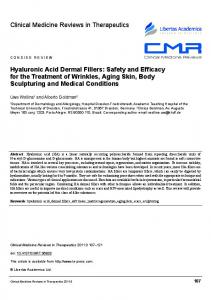
Rheological and nanoindentation analysis of 2% water swollen HA-MA hydrogel were conducted to understand their mechanical properties. Forswollen rheology, a stress controlled rheometer Rheological and nanoindentation analysis of 2% water HA-MA hydrogel were conducted MCR 501,mechanical Anton Parr,properties. Ashland, VA, USA) wasaused with a measuring system of parallel to (Physica understand their For rheology, stress controlled rheometer (Physica MCR plate geometry. The hydrogels were subjected to an oscillatory shear test with a frequency sweep 501, Anton Parr, Ashland, VA, USA) was used with a measuring system of parallel plate geometry. (0.1 to 10 Hz) were at a fixed strain to rate the storage (G′), loss modulus (G″),(0.1 andtocomplex The hydrogels subjected anwhile oscillatory shearmodulus test with a frequency sweep 10 Hz) at viscosity values were obtained. Figure 7b shows the stiffness HA-MA hydrogels,viscosity with thevalues G′ a fixed strain rate while the storage modulus (G0 ), loss modulusof(G”), and complex 0 being constant up to 3 Hz and then starting to decrease slowly with increase in frequency. There was were obtained. Figure 7b shows the stiffness of HA-MA hydrogels, with the G being constant up difference between G′ and slowly G″ for most of thein frequency range tested. G″aincreased to a3significant Hz and then starting to decrease with part increase frequency. There was significant gradually after around 0.7 Hz crossing G′ around 8 Hz. At 1 Hz, G′ was around 162 Pa 0 difference between G and G” for most part of the frequency range tested. G” increased gradually after corresponding to a Young’s modulus (E′) of around 5 Pa [42]. Figure 7c shows the complex viscosity around 0.7 Hz crossing G0 around 8 Hz. At 1 Hz, G0 was around 162 Pa corresponding to a Young’s decreasing linearly with frequency. This is representative of the shear thinning of hydrogels that modulus (E0 ) of around 5 Pa [42]. Figure 7c shows the complex viscosity decreasing linearly with results from the phenomenon related to the dynamics of mechanical energy dissipation in entangled frequency. This is representative of the shear thinning of hydrogels that results from the phenomenon chains of hydrogel network. For nanoindentation, a G200 nanoindenter (Agilent Technologies, related to the dynamics of mechanical energy dissipation in entangled chains of hydrogel network. Singapore) machine was used with a diamond cono-spherical tip (apex radius of 5 μm) to calculate ForE′.nanoindentation, a G200 nanoindenter (Agilent Technologies, machine was used with The indentation was conducted at high-resolution mode with Singapore) the tip set to ultrasensitive mode 0 a diamond tipset (apex 5 µm)7d toshows calculate E . of The indentation was and speedcono-spherical of tip approach to 20radius nm/s.of Figure a plot force exerted on theconducted hydrogel at high-resolution mode with the tip set to ultrasensitive mode and speed of tip approach set to of 20five nm/s. surface against the displacement observed during the unloading process. It shows the results Figure 7d shows a plot ofover forcefive exerted on the hydrogel surface against hydrogel. the displacement observed indentations performed different locations across the HA-MA The average E′ during the unloading process. It shows curve the results of fivetoindentations over five different obtained from the force-displacement was found be around 8performed Pa which is similar to the locations across the HA-MA hydrogel. The average E0 obtained from the force-displacement curve was biological cupula. found to berigid around Pa which is similar thehydrogel biologicalcupula cupula. The yet 8 porous structure of thetoHA improves the sensitivity of the MEMS sensor by enhancing the fluid motion induced viscous dragimproves forces [12,19]. Besides of these properties, The rigid yet porous structure of the HA hydrogel cupula the sensitivity the MEMS sensor the hydrogel cupula increases the overall surface area exposed to the incoming flow stimulus, which by enhancing the fluid motion induced viscous drag forces [12,19]. Besides these properties, the hydrogel increases the drag thus enhancing the sensitivity. viscous coupling of the cupula and thethe cupula increases the force overall surface area exposed to the The incoming flow stimulus, which increases very lowthus relaxation times reduce the random noises,coupling low frequency noises,and andthe diminish therelaxation effects drag force enhancing the sensitivity. The viscous of the cupula very low of Brownian motion, thereby enhancing the signal to noise ratio of the sensor [19,23,24,42]. times reduce the random noises, low frequency noises, and diminish the effects of Brownian motion, Therefore, in order improve the sensitivity the sensor, it is very important to understand thethe thereby enhancing theto signal to noise ratio of theof sensor [19,23,24,42]. Therefore, in order to improve morphological and material properties of the HA-MA hydrogel. Increased surface area, sensitivity of the sensor, it is very important to understand the morphological and material properties of the hydrophilicity of the polymer material, friction component due to interaction of surrounding water HA-MA hydrogel. Increased surface area, hydrophilicity of the polymer material, friction component due with the water trapped in pores of hydrogel matrix could contribute towards the enhancement of to interaction of surrounding water with the water trapped in pores of hydrogel matrix could contribute viscous drag forces and thereby the sensitivity [12]. towards the enhancement of viscous drag forces and thereby the sensitivity [12].
Figure 7. Characterization of 2% HA-MA hydrogel: (a) SEM of a cross-section ofhydrogel dried Figure 7. Characterization of 2% HA-MA hydrogel: (a) SEM imageimage of a cross-section of dried hydrogel sample theofnetwork of Frequency pores; (b) Frequency plot the showing the stiffness constant of sample showing theshowing network pores; (b) sweep plotsweep showing constant stiffnessindependent of hydrogel of independent of frequency to 3 Hz; viscosity (c) Complex showing hydrogel frequency range up to 3range Hz; (c)upComplex plotviscosity showingplot shear thinning shear with thinning behavior with (d) increasing frequency; Nanoindentation plot showing behavior increasing frequency; Nanoindentation plot(d) showing force-displacement curves for force-displacement for five hydrogel surface locations. five hydrogel surfacecurves locations.
Sensors 2017, 17, 1728
11 of 14
Sensors 2017, 17, 1728
11 of 14
5. Experimental Results 5. Experimental Results We have conducted proof-of-concept experiments to determine the flow sensing performance of We have conducted proof-of-concept experiments to determine the flow sensing performance the biomimetic MEMS sensor. Both the naked hair cell sensor and the hydrogel-capped sensors were of the biomimetic MEMS sensor. Both the naked hair cell sensor and the hydrogel-capped sensors tested to investigate the enhancement in the sensing performance of the sensor due to the biomimetic were tested to investigate the enhancement in the sensing performance of the sensor due to the cupula-inspired hydrogel capping. The full-bridge circuit was biased with a DC voltage of 5V and biomimetic cupula-inspired hydrogel capping. The full-bridge circuit was biased with a DC voltage the output from the sensor is connected to a National Instruments data acquisition card (NI-DAQ, of 5V and the output from the sensor is connected to a National Instruments data acquisition card USB-6289 M-series model, National Instrument, Austin, TX, USA) and is recorded using the Signal (NI-DAQ, USB-6289 M-series model, National Instrument, Austin, TX, USA) and is recorded using Express module of the LABVIEW software. the Signal Express module of the LABVIEW software. Figure 8b shows the output of the naked hair cell sensor for a stimulus of five pulses of airflow Figure 8b shows the output of the naked hair cell sensor for a stimulus of five pulses of airflow past the sensor. As it can be seen, the sensor produced five distinct and well-defined peaks at the past the sensor. As it can be seen, the sensor produced five distinct and well-defined peaks at the time instants when the air flow past the hair cell. In another experiment, in order to investigate the time instants when the air flow past the hair cell. In another experiment, in order to investigate the improvement in the sensitivity of the sensor due to the presence of the hydrogel capping, both the improvement in the sensitivity of the sensor due to the presence of the hydrogel capping, both the naked hair cell (SU-8 hair cell) sensor and the hydrogel-capped sensor were placed in the presence of naked hair cell (SU-8 hair cell) sensor and the hydrogel-capped sensor were placed in the presence of a flow velocity of 0.1 m/s. Figure 8c shows the output of both these sensors. It can be seen that the a flow velocity of 0.1 m/s. Figure 8c shows the output of both these sensors. It can be seen that the hydrogel-capped sensor showed a much higher output voltage in response to the flow. The presence hydrogel-capped sensor showed a much higher output voltage in response to the flow. The presence of the cupula increases the overall surface area exposed to the flow and thereby enhances the drag of the cupula increases the overall surface area exposed to the flow and thereby enhances the drag force experienced by the structure offering additional sensitivity to the sensor. The HA-MA hydrogel force experienced by the structure offering additional sensitivity to the sensor. The HA-MA used is highly absorbant with 85% water in them and also a similar density to water. In addition, hydrogel used is highly absorbant with 85% water in them and also a similar density to water. In the porosity and hydrophilicity of hydrogels can help in increasing the signal transmission from the addition, the porosity and hydrophilicity of hydrogels can help in increasing the signal transmission flow to the embedded hair cell. There exists a coupling interaction between the external flow and the from the flow to the embedded hair cell. There exists a coupling interaction between the external water trapped in the loose semi-permeable pores of hydrogel matrix, thus increasing the hydrophilicity flow and the water trapped in the loose semi-permeable pores of hydrogel matrix, thus increasing increases the drag force. Therefore, the presence of the cupula offers both mechanical and material the hydrophilicity increases the drag force. Therefore, the presence of the cupula offers both contributions towards the enhancement of sensitivity of the sensor. mechanical and material contributions towards the enhancement of sensitivity of the sensor.
Figure Figure 8. 8. Experimental Experimental flow flow sensing sensing results: results: (a) (a) MEMS MEMS sensor sensor with with biomimetic biomimetic hydrogel hydrogel capping capping on on the hair cell; (b) Response of the naked hair cell sensor to five pulses of air flow of velocity the hair cell; (b) Response of the naked hair cell sensor to five pulses of air flow of velocity 0.2 0.2 m/s; m/s; (c) (c) Comparison Comparison of of the the output output of of the the hydrogel-capped hydrogel-capped sensor sensor with with respect respect to to that that of of the the naked naked hair hair cell cell sensor in response to a flow velocity of 0.1 m/s. sensor in response to a flow velocity of 0.1 m/s.
6. Discussion and Conclusions This work develops a MEMS flow sensor which features a 3D cylindrical hair cell inspired by the biological neuromast sensor present in the blind cavefish. The MEMS sensor consists of a 2 μm thick silicon sensing membrane, which consists of gold strain gauges patterned and connected into a
Sensors 2017, 17, 1728
12 of 14
6. Discussion and Conclusions This work develops a MEMS flow sensor which features a 3D cylindrical hair cell inspired by the biological neuromast sensor present in the blind cavefish. The MEMS sensor consists of a 2 µm thick silicon sensing membrane, which consists of gold strain gauges patterned and connected into a full-bridge circuit. As compared to the bioinspired hair cell sensors developed in the past, this sensor features three key advantages. First, the sensor design eliminates the need for an external Wheatstone bridge circuit since the full-bridge circuit is achieved on the sensing membrane itself. Second, full-bridge circuit on membrane as compared to the quarter bridge circuits developed in the past, allow a four times higher sensitivity. Third, the fabrication method monolithically integrates the 3D hair cell fabrication along with the fabrication of the MEMS sensing membrane and the dicing process. A biomimetic artificial cupula is synthesized using Hyaluronic acid hydrogel and drop-casted on the SU-8 hair cell. The presence of the artificial HA hydrogel cupula enhances the sensitivity of the sensor both due to mechanical and material contributions of the hydrogel. The hydrogel cupula increases the cross-sectional surface area exposed to flow as compared to the SU-8 hair cell and thereby increases the drag force experienced by the standing structure. Increased drag force in the presence of the cupula causes an enhanced bending moment on the membrane and a higher sensor output. In addition, the porous structural pockets of HA hydrogel filled with water and material permeability seem to have contributions in further enhancing the drag force. The paper describes in detail the design, fabrication and experimental characterization of the flow sensor. The methodology and fabrication techniques demonstrated in this work could guide the development of further biomimetic materials and sensors in future. Flexible arrays of such MEMS hair cell sensors representing the lateral-line in fish could be utilized on underwater vehicles to attain hydrodynamic vision and energy-efficient maneuverability that fishes naturally achieve. Acknowledgments: This research is supported by the National Research Foundation (NRF) Singapore under its Campus for Research Excellence and Technological Enterprise programme. The Center for Environmental Sensing and Modeling (CENSAM) is an interdisciplinary research group of the Singapore-MIT Alliance for Research and Technology (SMART). Author Contributions: A.G.P.K. conceived the idea, designed the experiments and conducted the experiments; M.B. performed the hydrogel synthesis and characterization, E.K. conducted the simulation analysis; M.A. analyzed the data; J.M.M. provided the laboratory facilities; M.S.T. supervised the research. Conflicts of Interest: The authors declare no conflict of interest.
References 1. 2. 3. 4. 5. 6. 7. 8. 9.
Bhushan, B. Biomimetics: Lessons from nature—An overview. Philos. Trans. A Math. Phys. Eng. Sci. 2007, 367, 1445–1486. [CrossRef] [PubMed] Wasling, H.B.; Norrsell, U.; Gothner, K.; Olausson, H. Tactile directional sensitivity and postural control. Exp. Brain Res. 2005, 166, 147–156. [CrossRef] [PubMed] Barth, F.G. A Spiders World: Senses and Behavior; Springer: New York, NY, USA, 2002. Terashima, S.; Goris, R.C. Infrared Receptors and the Trigeminal Sensory System; Harwood: Amsterdam, The Netherlands, 1999. Dehnhardt, G.; Mauck, B.; Bleckmann, H. Seal whiskers detect water movements. Nature 1998, 394, 235–236. [CrossRef] Montgomery, J.C.; Baker, C.F.; Carton, A.G. The lateral-line can mediate rheotaxis in fish. Nature 1997, 389, 960–963. [CrossRef] Montgomery, J.C.; Coombs, S.; Baked, C.F. The mechanosensory lateral line system of the hypogean form of Astyanax fasciatus. Environ. Biol. Fishes 2001, 62, 87–96. [CrossRef] Coombs, S. Smart Skins: Information processing by lateral line flow sensors. Auton. Robot. 2011, 11, 255–261. [CrossRef] Teyke, T. Morphological differences in neuromasts of the blind cave fish Astyanax hubbsi and the sighted river fish Astyanax mexicanus. Brain Behav. Evol. 1990, 35, 23–30. [CrossRef] [PubMed]
Sensors 2017, 17, 1728
10. 11. 12. 13.
14.
15. 16.
17.
18.
19.
20.
21. 22.
23.
24.
25.
26.
27.
28.
13 of 14
Jielof, R.; Spoor, A.; de Vries, H. The microphone activity of the lateral-line. J. Physiol. 1952, 116, 137–157. [CrossRef] [PubMed] Kelly, J.P.; van Netten, S.M. Topography and mechanics of the cupula in the fish lateral-line. I. Variation of cupular structure and composition in the three dimensions. J. Morphol. 1991, 207, 23–36. [CrossRef] [PubMed] McConney, M.E.; Anderson, K.D.; Brott, L.L.; Naik, R.R.; Tsukruk, V.V. Bioinspired material approaches for sensing. Adv. Funct. Mater. 2009, 19, 2527–2544. [CrossRef] Engel, J.M.; Chen, J.; Chen, N.; Pandya, S.; Liu, C. Development and characterization of an artificial hair cell based on polyurethane elastomer and force sensitive resistors. In Proceedings of the IEEE Sensors Conference, Irvine, CA, USA, 31 October–3 November 2005; pp. 1014–1017. Kottapalli, A.G.P.; Asadnia, M.; Miao, J.M.; Barbastathis, G.; Triantafyllou, M. A flexible liquid crystal polymer MEMS pressure sensor array for fish-like underwater sensing. Smart Mater. Struct. 2012, 21, 115030. [CrossRef] Kottapalli, A.G.P.; Asadnia, M.; Miao, J.M.; Barbastathis, G.; Triantafyllou, M. Polymer MEMS pressure sensor arrays for fish-like underwater sensing applications. IET Micro Nano Lett. 2012, 7, 1189–1192. [CrossRef] Kottapalli, A.G.P.; Tan, C.W.; Olfatnia, M.; Miao, J.M.; Barbastathis, G.; Triantafyllou, M. A liquid crystal polymer membrane MEMS sensor for flow rate and flow direction sensing applications. J. Micromech. Microeng. 2011, 13, 085006. [CrossRef] Kottapalli, A.G.P.; Asadnia, M.; Miao, J.M.; Barbastathis, G.; Triantafyllou, M. Soft polymer membrane micro-sensor arrays inspired by the mechanosensory lateral line on the blind cavefish. J. Intell. Mater. Syst. Struct. 2015, 26, 38–46. [CrossRef] Chen, N.; Tucker, C.; Engel, J.M.; Yang, Y.; Pandya, S.; Liu, C. Design and characterization of artificial haircell sensor for flow sensing with ultrahigh velocity and angular sensitivity. J. Microelectromech. Syst. 2007, 16, 999–1014. [CrossRef] Peleshenko, S.; Julian, M.D.; Ornatska, M.; McConney, M.E.; LeMieux, M.C.; Chen, N.; Tucker, C.; Yang, Y.; Liu, C.; Humphrey, J.A.C.; et al. Hydrogel-encapsulated microfabricated hair cells mimicking fish cupula neuromast. Adv. Mater. 2007, 19, 2903–2909. [CrossRef] McConney, M.E.; Chen, N.; Lu, D.; Hu, H.A.; Coombs, S.; Liu, C.; Tsukruk, V.V. Biologically inspired design of hydrogel-capped hair sensors for enhanced underwater flow detection. Soft Matter 2009, 5, 292–295. [CrossRef] Kottapalli, A.G.P.; Asadnia, M.; Miao, J.M.; Triantafyllou, M. Touch at a distance sensing: Lateral-Line inspired MEMS flow sensors. Bioinspir. Biomim. 2014, 9, 046011. [CrossRef] [PubMed] Kottapalli, A.G.P.; Asadnia, M.; Miao, J.M.; Triantafyllou, M.S. Electrospun nanofibrils encapsulated in hydrogel cupula for biomimetic MEMS flow sensor development. In Proceedings of the 26th International Conference on Micro Electro Mechanical Systems (MEMS), Taipei, Taiwan, 22–24 January 2013; IEEE: Washington, DC, USA, 2013. Kottapalli, A.G.P.; Bora, M.; Asadnia, M.; Miao, J.; Venkatraman, S.S.; Triantafyllou, M. Nanofibril scaffold assisted MEMS artificial hydrogel neuromasts for enhanced sensitivity flow sensing. Sci. Rep. 2016, 6, 19336. [CrossRef] [PubMed] Asadnia, M.; Kottapalli, A.G.P.; Karavitaki, K.D.; Warkiani, M.E.; Miao, J.M.; Corey, D.P. From Biological Cilia to Artificial Flow Sensors: Biomimetic Soft Polymer Nanosensors with High Sensing Performance. Sci. Rep. 2016, 6, 32955. [CrossRef] [PubMed] Asadnia, M.; Kottapalli, A.G.P.; Shen, Z.; Miao, J.M.; Triantafyllou, M.S. Flexible and surface mountable piezoelectric sensor arrays for underwater sensing in marine vehicles. IEEE Sens. J. 2013, 13, 3918–3925. [CrossRef] Asadnia, M.; Kottapalli, A.G.P.; Miao, J.M.; Randles, A.B.; Sabbagh, A.; Kropelnicki, P.; Tsai, J.M. High temperature characterization of PZT(0.52/0.48) thin-film pressure sensors. J. Micromech. Microeng. 2014, 24, 015017. Kottapalli, A.G.P.; Asadnia, M.; Hans, H.; Miao, J.M.; Triantafyllou, M.S. Harbor seal whisker inspired flow sensor to reduce vortex induced vibrations. In Proceedings of the 28th International Conference on Micro Electro Mechanical Systems (MEMS), Estoril, Portugal, 18–22 January 2014; pp. 889–892. Dijkstra, M.; van Baar, J.J.; Wiegerink, R.J.; Lammerink, T.S.J.; de Boer, J.H.; Krijnen, G.J.M. Artificial sensory hairs based on the flow sensitive receptor hairs of the crickets. J. Micromech. Microeng. 2005, 15, S132–S138. [CrossRef]
Sensors 2017, 17, 1728
29. 30. 31.
32. 33.
34. 35.
36. 37. 38. 39. 40.
41.
42.
14 of 14
Klein, A.; Bleckmann, H. Determination of object position, vortex shedding frequency and flow velocity using artificial lateral line canals. Beilstein J. Nanotechnol. 2011, 2, 276–283. [CrossRef] [PubMed] Abdulsadda, A.T.; Tan, X. An artificial lateral line system using IPMC sensor arrays. Int. J. Smart Nano Mater. 2012, 3, 226–242. [CrossRef] Yilmazoglu, O.; Yadav, S.; Cicek, D.; Schneider, J.J. A nano-microstructured artificial-hair-cell-type sensor based on topologically graded 3D carbon nanotube bundles. Nanotechnology 2016, 27, 365502. [CrossRef] [PubMed] Qualtieri, A.; Rizzi, F.; Epifani, G.; Ernits, A.; Kruusmaa, M.; De Vittorio, M. Parylene coated bioinspired artificial hair cell for liquid flow sensing. Microelectron. Eng. 2012, 98, 516–519. [CrossRef] Yang, Y.C.; Chen, J.; Engel, J.; Pandya, S.; Chen, N.; Tucker, C.; Coombs, S.; Jones, D.L.; Liu, C. Distant touch hydrodynamic imaging with an artificial lateral line. Proc. Natl. Acad. Sci. USA 2006, 103, 18891–18895. [CrossRef] [PubMed] Yang, Y.C.; Klein, A.; Bleckmenn, H.; Liu, C. Artificial lateral line canal for hydrodynamic detection. Appl. Phys. Lett. 2011, 99, 023701. [CrossRef] Abels, C.; Qualtieri, A.; De Vittorio, M.; Megill, W.M.; Rizzi, F. A bio-inspired real-time capable artificial lateral line system for freestream flow measurements. Bioinspir. Biomimet. 2016, 11, 035006. [CrossRef] [PubMed] Tao, J.; Yu, X.B. Hair flow sensors: From bio-inspiration to bio-mimicking—A review. Smart Mater Struct. 2012, 21, 113001. [CrossRef] Rizzi, F.; Qualtieri, A.; Dattoma, T.; Epifani, G.; De Vittorio, M. Biomimetics of underwater hair cell sensing. Microelectron. Eng. 2015, 132, 90–97. [CrossRef] Liu, G.; Wang, A.; Wang, X.; Liu, P. A review of artificial lateral line in sensor fabrication and bionic applications for robot fish. Appl. Bionics Biomech. 2016, 2016. [CrossRef] [PubMed] Schomburg, W.K.; Rummler, Z.; Shao, P.; Wuff, K.; Xie, L. The design of metal strain gauges on diaphragms. J. Micromech. Microeng. 2004, 14, 1101–1108. [CrossRef] Smeds, K.A.; Pfister-Serres, A.; Miki, D.; Dastgheib, K.; Inoue, M.; Hatchell, D.L.; Grinstaff, M.W. Photocrosslinkable polysaccharides for in situ hydrogel formation. J. Biomed. Mater Res. 2000, 54, 115–121. [CrossRef] Baier, L.J.; Bivens, K.A.; Patrick, C.W., Jr.; Schmidt, C.E. Photocrosslinked Hyaluronic Acid Hydrogels: Natural, Biodegradable Tissue Engineering Scaffolds. Biotechnol. Bioeng. 2003, 82, 578–589. [CrossRef] [PubMed] Anderson, K.D.; Lu, D.; McConney, M.E.; Han, T.; Reneker, D.H.; Tsukruk, V.V. Hydrogel microstructures combined with electrospun fibers and photopatterning for shape and modulus control. Polymer 2008, 49, 5284–5293. [CrossRef] © 2017 by the authors. Licensee MDPI, Basel, Switzerland. This article is an open access article distributed under the terms and conditions of the Creative Commons Attribution (CC BY) license (http://creativecommons.org/licenses/by/4.0/).