Current Controlled Current Conveyor-Based Currentmode Universal Filter Winai Jaikla* and Montree Siripruchyanun† *
Electric and Electronic Program, Faculty of Industrial Technology, Suan Sunandha Rajabhat University, Dusit, Bangkok, 10300, THAILAND Tel: +66-2-243-2240 Ext. 317, Fax: +66-2-241-5935, E-mail:
[email protected] † Department of Teacher Training in Electrical Engineering, Faculty of Technical Education, King Mongkut’s University of Technology North Bangkok, Bangkok, 10800, THAILAND Tel: +66-2- 913-2500 Ext. 3328 Fax. +66-2-587-8255, E-mail:
[email protected]
Abstract— This article presents a current-mode universal biquadratic filter performing completely standard functions: low-pass, high-pass, band-pass, band-reject and all-pass functions, based-on dual-output current controlled current conveyor (DO-CCCII). The features of the circuit are that: the quality factor and pole frequency can be tuned orthogonally via the input bias currents: the circuit description is very simple, consisting of merely 4 DO-CCCIIs and 2 grounded capacitors. Without any external resistors and require component matching conditions, the proposed circuit is very suitable to further develop into an integrated circuit. The PSPICE simulation results are depicted. The given results agree well with the theoretical anticipation. The maximum power consumption is approximately 1.16mW at ±1.5V power supply voltages.
I.
[7-8]. However, the parasitic resistance at x (Rx) port of CCII is limited and cannot be controlled, when it is used in some circuits, it must unavoidably require some external passive components, especially the resistors. This makes it not appropriate for IC implementation due to occupying more chip area, high power dissipation and absence of electronic controllability. On the other hand, the introduced secondgeneration current-controlled conveyor (CCCII) [9] has the advantage of electronic adjustability over the CCII. Due to the above reasons, it is beneficial to use the CCCIIs as basic active building blocks to realize various current-mode active filters. As a result, numerous realizations of currentmode biquadratic filters using CCCIIs have thus been previously reported [10-19]. However, all of these realizations have at least one of the following inconveniencies: • Require changing circuit topologies to achieve several functions [16]. • Some outputs of the filter responses are not in high output impedance [11, 12, 18]. • Cannot provide completely standard functions [10, 11, 14, 16, 17, 19]. • Use of floating capacitor, which is not appropriate to further fabricate in IC [13, 16]. • The quality factor and pole frequency can not be tuned orthogonally [11, 13, 15, 16]. • Require component matching conditions to achieve several functions [18]. The aim of this paper is to propose a current-mode universal biquadratic filter, emphasizing on use of DOCCCIIs. The features of proposed circuit are that: the proposed universal filter can provide completely standard functions without changing circuit topology: the circuit description is very simple, it uses only grounded capacitors, which is suitable for further fabricating in monolithic chip: quality factor and pole frequency can be independently adjusted. The performances of proposed circuit are illustrated by PSPICE simulations, they show good agreement as mentioned.
INTRODUCTION
An analog filter has become a standard research topic since it can be applied in areas like communication, measurement and instrumentation and control systems [1-2]. One of most popular analog filters is a universal biquadratic filter since it can provide several functions. Nowadays, a universal filter working in current-mode has being been more popular than voltage-mode one. Due to since the last decade, there has been much effort to reduce the supply voltage of analog systems. This is due to the command for portable and batterypowered equipment. Since a low-voltage operating circuit becomes necessary, the current–mode technique is ideally suited for this purpose. Actually, a circuit using the currentmode technique has many other advantages: for example, larger dynamic range, higher bandwidth, greater linearity, simpler circuitry and lower power consumption [3-4]. The second generation current conveyor (CCII) is a reported active component especially suitable for a class of analog signal processing [5]. The fact that the device can operate in both current and voltage-modes, providing flexibility and enables a variety of circuit designs. In addition, it can offer advantageous features such as high slew rate, higher speed, wide bandwidth and simple implementation [56]. Also, the use of dual-output current conveyors is found to be useful in the derivation of current-mode single input three output filters using a reduced number of active components
978-1-4244-4522-6/09/$25.00 ©2009 IEEE
893
ISCIT 2009
II.
PRINCIPLE OF OPERATION I LP = I in
A.
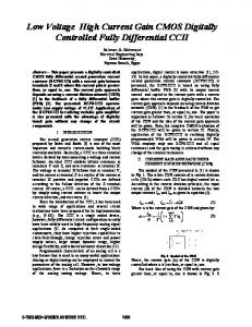
Dual-output Second-generation Current-Controlled Current Conveyor (DO-CCCII) Since the proposed circuit is based on DO-CCCIIs, it will be introduced in this section. Traditionally, the DO-CCCII is a versatile analog building block which is similar to the conventional dual-output current conveyor (DO-CCII) except that the DO-CCCII has a finite input resistance RX at the X terminal. DO-CCCII has the advantage of electronically adjustability over the DO-CCII, because it allows the adjustment of the X-terminal intrinsic resistance RX via the bias current IB as shown by RX =
VT , 2I B
I BS I in
I AP I in
where VT is the thermal voltage. The relationship between the voltage and current variables among port X, Y and Z of an ideal DO-CCCII can be described by the following equation
+Z Y DO − CCCII −Z X
I in
(a)
X
IZ + IZ −
IZ + = −IZ −
Z− = IX
−z
X
1 −z
−z
Y
4 −z
Proposed Current-mode Universal Biquad Filter The proposed current-mode universal filter is shown in Fig. 2, where IB1, IB2, IB3 and IB4 are input bias currents of DOCCCII1, DO-CCCII2, DO-CCCII3 and DO-CCCII4, respectively. Straightforwardly analyzing the circuit in Fig. 2, the transfer functions of this circuit can be obtained as
I BP I in
, 1 1 + C1 RX 3 C1C2 RX 1 RX 2 1 −s C1 RX 3 = , 1 1 s2 + s + C1 RX 3 C1C2 RX 1 RX 2
−z
X
2 +z
DO − CCCII
C2
I LP
I B3
X
B.
s2
(7)
C1 I HP
Y
−z
X
3 −z
DO − CCCII
I BP
Proposed Current-mode Universal Filter
From Eqs. (3)-(7), the pole frequency and quality factor can be expressed as
DO-CCCII (a) Symbol (b) Equivalent circuit
I HP = I in s2 + s
Y
IB4
Fig. 2.
(b) Fig. 1.
Y
DO − CCCII
Z+
(6)
IB2
DO − CCCII
IB
1 I X RX
1 C1C2 RX 1 RX 2 = , 1 1 2 s +s + C1 RX 3 C1C2 RX 1 RX 2 1 1 s2 − s + C1 RX 3 C1C2 RX 1 RX 2 = . 1 1 2 s +s + C1 RX 3 C1C2 RX 1 RX 2 s2 +
I B1
(2)
The symbol and the equivalent circuit of the DO-CCCII are illustrated in Fig. 1.
Y
(5)
Moreover, the band-stop and the all-pass transfer functions can be obtained from the currents IBS=ILP+IHP, IAP=IBS+IBP, respectively. It yields
(1)
iY = 0, VX = β VY + RX I X , iZ + = −iZ − = iX .
1 C1C2 RX 1 RX 2 . 1 1 s2 + s + C1 RX 3 C1C2 RX 1 RX 2
ω0 =
1 , C1C2 RX 1 RX 2
Q0 = RX 3
C1 , C 2 R X 1 RX 2
(8) (9)
where RXi = VT / 2 I Bi , Eqs. (8) and (9) are subsequently
(3)
modified to
ω0 =
1 2VT
Q0 =
1 I B3
(4)
894
I B1 I B 2 , C1C2
(10)
C1 I B1 I B 2 . C2
(11)
From Eqs. (10) and (11), we found that the quality factor can be adjusted independently from the pole frequency by varying IB3. Furthermore, the pole frequency can be adjusted by IB1, and IB2. Thus bandwidth (BW) is given by BW =
ω0
=
Q0
2I B3 . VT C1
I BS = I in
(12)
I AP = I in
In the same view, the bandwidth can be linearly tuned by IB3. Another advantage of the proposed circuit is that the high Q0 circuit can be obtained by setting IB3, as much as required. C.
γ 4 s2 + s2 + s
S
Q0 I B1
=S
Q0 IB 2
=S
1 1 = ; SCQ20 = − ; S IQB03 = −1 , 2 2
Q0 C1
S IBW = 1; SVBW = SCBW = −1 . B3 T 1
(13) Q0 = (14)
VX = β VY + RX I X ,
(16a)
IZ + = α I X ,
(16b)
I Z − = −γ I X ,
(16c)
III.
I BP =− I in
I LP =− I in
s 2
s +s
(17)
+
C1C2 RX 1 RX 2 γ 1γ 4 β1 C1 RX 3
γ 4γ 3 β 3 C1 RX 3
+
α1γ 2γ 4 β1 β 2
,
(18)
.
(19)
C1C2 RX 1 RX 2
α1γ 2γ 4 β1 β 2
C1C2 RX 1 RX 2
2
s +s
γ 4γ 3 β3 C1 RX 3
+
α1γ 2γ 4 β1 β 2
α1γ 2γ 4 β1 β 2
C1C2 RX 1 RX 2
α1γ 2γ 4 β1 β 2
.
(21)
C1C2 RX 1 RX 2
α1γ 2γ 4 β1 β 2
C1C2 RX 1 RX 2
RX 3
γ 3 β3
,
α1γ 2 β1 β 2 C1 . γ 4 C2 R X 1 RX 2
(22)
(23)
ω0
Q0
=
γ 3γ 4 β 3 C1 RX 3
.
(24)
SIMULATION RESULTS
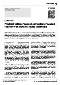
To prove the performances of the proposed circuit, the PSPICE simulation program was used. The PNP and NPN transistors employed in the proposed circuit were simulated by respectively using the parameters of the PR200N and NR200N bipolar transistors of ALA400 transistor array from AT&T [20]. Fig. 3 depicts schematic description of the DOCCCII used in the simulations. All DO-CCCIIs were biased with ±1.5V power supplies, C1=C2=10nF, Iin=20µA, and all bias currents equal to 50µA are chosen to obtain intrinsic resistances of 260Ω. Load of the circuit is 1Ω of resistor. It yields the pole frequency of 54.075kHz, while calculated value of this parameter from Eq. (10) is 61.24kHz (deviated by 11.47%). The results shown in Fig. 4 are the gain responses of the universal filter obtained from Fig. 2. Fig. 5 shows the gain and phase responses of all-pass filter. It can be clearly seen that the universal filter circuit can provide lowpass, high-pass, band-pass, band-reject and all-pass functions, simultaneously. Fig. 6 display gain responses of bandpass function for different IB3 values. It is clear that the quality factor can be adjusted by the input bias current IB3 as depicted in Eq. (11), without affecting the pole frequency. Maximum power consumption is about 1.16mW.
where α and γ are the frequency dependent current gains, besides β is the frequency dependent voltage gain. These gains are ideally equal to unity. Practically, they depend on the frequency of operation, temperature and transistor parameters of the DO-CCCII. In the case of non-idea and reanalyzing the proposed filter in Fig. 2, it subsequently yields the transfer functions to be
C1 RX 3
C1 RX 3
(20)
C1C2 RX 1 RX 2
+
+
,
Practically, the α, γ and β originate from intrinsic resistances and stray capacitances in the DO-CCCII. These errors affect the sensitivity to temperature and high frequency response of the proposed circuit, then the DO-CCCII should be carefully designed to achieve these errors as low as possible. Consequently, these deviations are very small and can be ignored.
Non-Ideal case For non-ideal case, the DO-CCCII can be respectively characterized with the following equations
s +s
γ 4γ 3 β 3
BW =
D.
2
C1 RX 3
α1γ 2γ 4 β1 β 2
Thus bandwidth is given by
(15)
γ 4s2 , γ 4γ 3 β 3 α1γ 2γ 4 β1β 2
γ 1γ 4 β1
ω0 =
Therefore, all the active and passive sensitivities are equal or less than unity in magnitude.
I HP = I in
C1 RX 3
+
In this case, the ω0 and Q0 are respectively changed to be
Circuit Sensitivities The sensitivities of the proposed circuit can be found as 1 1 S IωB01 = S IωB02 = ; SCω10 = SCω20 = − ; SVωT0 = −1 , 2 2
γ 4γ 3 β3
γ 4 s2 − s s2 + s
α1γ 2γ 4 β1 β 2
C1C2 RX 1 RX 2
C1C2 RX 1 RX 2
895
use in battery-powered, portable electronic equipments such as wireless communication system devices. REFERENCES [1] [2]
Fig. 3.
[3]
Internal Construction of DO-CCCII
[4]
Gain (dB)
[5] [6] [7]
Fig. 4.
Simulated Current Responses for LP, BP, HP and BS of the Proposed Current-mode Filter of Fig. 2
[8] [9] [10] [11]
Fig. 5.
Simulated Responses of the AP Filter
[12]
Gain (dB)
[13] [14] [15]
Fig. 6.
Proposed Band-pass Responses for Different Values of IB3 [16]
IV. CONCLUSIONS The current-mode universal biquadratic filter based on DOCCCIIs has been presented. The advantages of the proposed circuit are that: it performs low-pass, high-pass, band-pass, band-reject and all-pass functions from the same circuit configuration without component matching conditions and changing circuit topology: the quality factor and the pole frequency can be orthogonally controlled via input bias currents of the corresponding DO-CCCIIs, this is easily modified to use in control systems using a microcontroller [3]. The circuit description comprises only 4 DO-CCCIIs and 2 grounded capacitors, which is attractive for the point of view of IC implementation. With mentioned features, it is very suitable to realize the proposed circuit in monolithic chip for
[17]
[18] [19] [20]
896
A. S. Sedra, and K. C. Smith, Microelectronic circuits, 3rd ed., Florida: Holt, Rinehart and Winston, 1991. M. A. Ibrahim, S. Minaei, and H. A. Kuntman, “A 22.5 MHz currentmode KHN-biquad using differential voltage current conveyor and grounded passive elements,” Int. J. Electron. Commun. (AEU), vol. 59, pp. 311-318, 2005. C. Toumazou., F. J. Lidgey, and D. G. Haigh, Analogue IC design: the current-mode approach, London: Peter Peregrinus, 1990. D. R. Bhaskar, V. K. Sharma, M, Monis, and S. M. I. Rizvi, “New current-mode universal biquad filter,” Microelectronics Journal, vol. 30, pp. 837-839, 1999. K. C. Smith and A. Sedra, “The current conveyor-a new circuit building block,” IEEE Proc. vol. 56, pp. 1368–1369, 1968. A. Sedra and K. C. Smith, “A second-generation current conveyor and its applications,” IEEE Trans. Circuit Theory, vol. 17, pp. 132–134, 1970. K. Ikeda and Y. Tomita, “Realization of current-mode biquadratic filter using CCIIs with current followers,” Electronics and Communications in Japan, part 2, vol. 77, pp. 99-107, 1994. A. M. Soliman, “New current mode filters using current conveyors,” International Journal of Electronics and Communication (AEU), vol. 51, pp. 275-278, 1997. A. Fabre, O. Saaid, F. Wiest, and C. Boucheron, “Current controllable bandpass filter based on translinear conveyors,” Electron. Lett, vol. 31, pp.1727–1728, 1995. M. T. Abuelma'atti, “A novel mixed-mode current-controlled currentconveyor-based filter,” Active and passive electronic components, vol. 26, pp. 185-191, 2003. A. Fabre, O. Saaid, F. Wiest and C. Boucheron, “Current controlled bandpass filter based on translinear conveyors,” Electronics Letters, vol. 31, pp. 1727-1728, 1995. M.T Abuelma’atti and N.A. Tasadduq, “Universal current-controlled current-mode filter using the multiple-output translinear current conveyor,” Frequenz, vol. 52, pp. 252-254, 1998. E. Yuce, S. Minaei and O. Cicekoglu, “Universal current-mode active-C filter employing minimum number of passive elements,” Analog integrated circuits and signal Processing, vol. 42, pp. 169-171, 2006. S. Minaei and S. Türköz, “Current-mode electronically tunable universal filter using only plus-type current controlled conveyors and grounded capacitors,” ETRI Journal, vol.26, pp. 292-296, 2004. W. Tangsrirat and D. Prasertsom, “Electronically tunable lowcomponent-count current-mode biquadratic filter using dual-output current followers,” Electrical Engineering, 2006. S. Minaei, O. Çiçekoglu, H. Kuntman, S. Türköz, “High output impedance current-mode lowpass, bandpass and highpass filters using current controlled conveyors,” International Journal of Electronics, vol. 88, pp. 915-922, 2001. A. Fabre, O. Saaid, F. Wiest and C. Boucheron, “High-frequency high-Q BiCMOS current-mode bandpass filter and mobile communication application,” IEEE Journal of solid-stage circuits,, vol. 33, no. 4, pp. 614-625, 1998. M. T. Abuelma'Atti, N. A. Tasadduq, “New current-mode currentcontrolled filters using the current-controlled conveyor,” International Journal of Electronics, vol. 85, pp. 483-488, 1998. C. M. Chang, B. M. Al-Hashimi and J. N. Ross, “Unified active filter biquad structures,” IEE proc., Circuits devices syst., vol. 151, pp. 273277, 2004. D. R. Frey, “Log-domain filtering: an approach to current-mode filtering,” IEE Proc. Circuit Devices Syst., vol. 140, pp. 406-416, 1993.