5v → 3.0v pk/pk, configurable between 2µv → 10µv / ADU. 12.3 Watts.
Configurable for 18 Bit or 16 Bit ADC. < 3.5 ADU rms @ 18 Bits, < 2.0 ADU @ 16
Bits, ...
MONSOON Image Acquisition System Data Sheet Rev 1.0
950 N. Cherry Avenue, +1 520 318 8109 Tucson, AZ, 85719, USA www.noao.edu/ets/monsoon
features • Common architecture for Hybrid, CCD, and CMOS detector technology • Clean software interface for command, status and data handling • Scalable to accommodate single or large mosaics of detectors • Calibrated hardware to assure consistent and known performance • Open source technology – Constant peer revision and enhancement – All documentation available • Detector limited performance
applications • Detector characterization work • Large VIS & NIR focal planes • Replacement of obsolete detector controller technology • Technical cameras
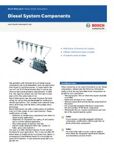
system components
description MONSOON is an NOAO "full open-source" development effort to address the need for detector-limited image acquisition for the next generation of astronomical instruments not only for NOAO but the entire astronomical community. New project initiatives at NOAO such as ORION, NEWFIRM, QUOTA, and ODI have defined the need for scalable, multichannel, high-speed image acquisition. Systems of this scale and performance raise new challenges in terms of communication bandwidth, data storage and data processing requirements which are not adequately met be currently existing astronomical controllers. In order to meet this demand, new techniques for not only a new detector controller but rather a new image acquisition architecture, have been defined. These extremely large scale imaging systems also raise less obvious concerns in previously neglected areas of controller design such as physical size and form factor issues, power dissipation and cooling near the telescope, system assembly/test/integration time, reliability, and total cost of ownership. Efforts have been made to use true commercial off the shelf (COTS) system elements, and find truly technology independent solutions for a number of system design issues whenever possible. This forward looking approach has moved our efforts at NOAO toward developing a modular, scalable architecture, which addresses the larger data pipeline and information flow issues, not simply device interface. In reference to the torrential summer rains of Tucson, and the flood of pixels defined by the next generation imaging systems, this system is named MONSOON. As alluded to above, MONSOON is more than a detector controller, it is a maturing image acquisition system architecture.
system architecture
firmware
MONSOON is based upon a stack of functional layers that are separated by concise interface control documents (ICDs). This architectural model allows a high degree of commonality between systems that support the requirements of different detector technologies. In addition, this model supports the scalability requirement to accommodate an arbitrary number of detectors in a focal plane.
This layer supports the hardware functionality and defines the interface to the software control layer. All hardware functions are mapped to address spaces within the DHE. This allows the software to control the DHE through a simply defined flat memory space using basic read and write commands. Firmware source code is written in VHDL and supplied as part of the open source license. An application specific micro controller is embedded within the MCB to deterministically control sequencing of detector control signals. This sequencer efficiently executes code that is downloaded to the MCB at system configuration time. The sequencer has the ability to control all hardware functions within the DHE i.e. clock and bias voltage levels, clock states, acquisition modes and timing, etc.
communications
hardware The architecture is physically manifested in four electronic modules that are supported by the core firmware and software suites. These functionally complimentary modules are then selected to populate a detector head electronics (DHE) crate that implements detector and instrument specific requirements. These four electronic modules are: • Master Control Board (MCB) - controls communication to the Pixel Acquisition Node (PAN) computer, DHE bus control, and detector clock sequencing • Clock and Bias Board (CLK) – produces low voltage biases and clock signals • IR Acquisition Board (IRACQ) - acquires up to 36 channels of DC coupled video signal • CCD Acquisition Board (CCDACQ) – conditions and acquires up to 8 channels of AC coupled video signal and provides high voltage biases For applications that might require additional or different functionality, the open source nature of MONSOON allows the confident re-use of functional sub-modules to create application specific boards with a relatively small investment in resources.
Interface Control Document group 6 (ICD 6.1) defines the protocol that is used for the Pixel Acquisition Node (PAN) to communicate with the firmware of the DHE. The currently implemented physical layer is a 1 Gbit (Optional 2.4 Gbit) fiber link module that interfaces to the DHE hardware via the FPDP standard protocol. A similar COTS device is employed in the Pixel Acquisition Node (PAN) PC.
software
All control functions for the system are performed by the PAN software suite. The software layer, called the Generic Pixel Server (GPX) and written in C, handles the system configuration tasks, client communications, pixel data acquisition, post acquisition processing and pixel data transfer transactions. For large focal planes where more than one DHE node is required a supervisor task acts as coordinator and command / message distributor. In all cases the client application, usually the Instrument Control System (ICS), sees one coherent focal plane at its disposition. All functions and parameters of the system are assigned to attribute name/value pairs by the software during an initial configuration process. The defined attributes are then manipulated to set and optimize system parameters to support different detectors and/or operational modes. This is done at a high level by commanding an ASCII mode file to be loaded by the system. To customize GPX to suit alternate detector types, it is only necessary to modify one library module.
toolsets A small application is available to provide stand alone control over any MONSOON system. This application, called the MONSOON Engineering Console (MEC), employs the same communication protocol (ICD 4.1) as that used by a normal client (e.g. the Instrument Control System). This provides a solid example for during client link development. The MEC supports the full capabilities of the MONSOON system and includes provision for scripting and logging. The MEC can be efficiently used to script and control test programs during detector characterization work. A Configuration Management Toolset is available to manage the complexity of connecting and configuring MONSOON to any focal plane. This application is based on XML technology and generates the documentation and run time configuration files for MONSOON systems.
specifications
Example MEC Screen Shots
DHE Chassis Backplane capacity and type
4, 6, or 8 Slot x 6U CPCI backplane
Size
6 Slot card cage 14 x 27 x 33 cm, 6 Slot enclosure 20 x 36 x 44 cm
Weight
6 Slot populated card cage 3.5 Kg, 6 Slot enclosure w/ps 13 Kg
Power Supply
Internal or optionally external to enclosure +5v, +3.3v logic; +/- 5v, +/-15v, +36v Analog
Detector cabling
Clear access at rear of enclosure via transition boards
Environmental conditions
-10 → +35oC 95% humidity non-condensing
DHE → PAN distance
300 meters
Master Control Board PAN command execution time
120ns
Sequencer type and memory depth
Application specific MPU in FPGA, 4K code store, 1.5K pattern store
Sequencer clock resolution
50ns
Integration timer resolution and capacity
Configurable 100ns, 1µs, 100ns, 1ms – 32 bit count up register
Pixel data rate
Maximum 50 Mpixel/sec with SLM100, 80 Mpixel/sec with SLM240
Diagnostic channels
Temperature, serial number, synthetic pixel generator, firmware rev.
Auxiliary functions
Master/Slave DHE sync logic, HS Serial link, 8 x temperature monitor
Board power consumption
7.5 Watts
Clock and Bias Board Clock signals
32 x Bi-level + 8 x 256 level clocks (Fast bias Dacs)
Clock signal voltage adjustment range
Jumper for 0 → 12.5v, 0 → -12.5v, and Bipolar +/- 12.5v
Clock signal voltage setting resolution
50mv / 100mv – Voltage adjustment via software command
Clock signal current source/sink
30ma - Provision for detector protection schemes
Clock signal noise (BW < 20MHz)
< 2mv rms
Clock and Bias Board (cont) Clock rise / fall time
Configurable, minimum 50ns
Bias signals
36
Bias signal voltage adjustment range
Jumper for 0 → 12.5v, 0 → -12.5v, and Bipolar +/- 12.5v
Bias signal current source / sink
10 ma
Bias signal voltage setting resolution
50mv / 100mv – Voltage adjustment via software command
Bias signal noise (BW < 20MHz)
< 250µv rms
Diagnostic channels
Power + reference voltages + clocks voltages + biases voltages and currents + board temperature + serial number + firmware rev.
Board power consumption
8 Watts
IR Acquisition Board Video signal channels
18 or 36 single ended or quasi-differential inputs, DC coupled
Video signal dynamic range and sensitivity
0.25v → 2.5v pk/pk, configurable between 4µv → 38µv / ADU
Video signal common mode voltage range
+/- 6v with respect to ground
Video signal channel acquisition rate
1 Mpixel/sec/channel
Video signal channel noise and linearity
< 1.7 ADU rms, < 0.01% INL @ 800KPixel/Sec.
Digital dynamic range
16 Bits
Digital filtering
1 → 64 digital averages on each pixel
Diagnostic channels
Board temperature + synthetic data generator + serial number + firmware rev.
Board power consumption
11.2 Watts
8 Channel CCD Acquisition Board Video signal channels
8 single ended AC coupled - P and N channel device compatible
Video signal dynamic range and sensitivity
0. 5v → 3.0v pk/pk, configurable between 2µv → 10µv / ADU
Video signal acquisition process
Dual slope CDS with DC restore
Video signal channel acquisition rate
Maximum 800 Kpixel/Sec @ 18 Bit, 1 Mpixel/sec @ 16 Bit.
Video signal channel noise and linearity
< 3.5 ADU rms @ 18 Bits, < 2.0 ADU @ 16 Bits, < 0.01% INL @ 500K Pixel/Sec
Digital dynamic range
Configurable for 18 Bit or 16 Bit ADC
HV bias signals
32
HV bias signal voltage adjustment range
Jumper for 0 → 35v, 0 → -35v, and Bipolar +/- 18v
HV bias signal current source / sink
30ma
HV bias signal voltage setting resolution
9mv
HV bias signal noise (BW < 20MHz)
< 250 µv rms
Diagnostic channels
All HV biases + board temperature + serial number + synthetic data generator + firmware rev.
Auxiliary functions
32 bit high speed output port - 3.3v and 5v logic compatible
Board power consumption
12.3 Watts