Invited paper
Current Optical Technologies for Wireless Access E. Leitgeb*, M. S. Awan*, P. Brandl*, T. Plank*, C. Capsoni**, R. Nebuloni**, T. Javornik***, G. Kandus***, S. Sheikh Muhammad#, F. Ghassemlooy ##, M. Löschnigg*, F. Nadeem* * Institute of Broadband Communication, TU Graz, Inffeldgasse 12/I, 8010 Graz, Austria ** Politecnico di Milano, Milan, in cooperation with IEIIT-Consiglio Nazionale delle Ricerche, Milan, Italy *** Department of Digital Communications and Networks, Jozef Stefan Institute, Ljubljana, Slovenia # National University of Computer and Emerging Sciences (FAST-NU), Lahore, Pakistan ## Northumbria University, Newcastle, UK
[email protected]
Abstract – The objective of this paper is to describe recent activities and investigations on free-space optics (FSO) or optical wireless and the excellent results achieved within SatNEx an EU-framework 6th programme and IC 0802 a COST action. In a first part, the FSO technology is briefly discussed. In a second part, we mention some performance evaluation criterions for the FSO. In third part, we briefly discuss some optical signal propagation experiments through the atmosphere by mentioning network architectures for FSO and then discuss the recent investigations in airborne and satellite application experiments for FSO. In part four, we mention some recent investigation results on modelling the FSO channel under fog conditions and atmospheric turbulence. Additionally, some recent major performance improvement results obtained by employing hybrid systems and using some specific modulation and coding schemes are presented. Keywords: Free-Space Optics, Broadband Wireless, Network Architectures, Last Mile Access, reliability and availability, Optical Wireless Systems
I.
FSO INTRODUCTION
A Free-Space Optics communication system consists of an optical transmitter which is mostly realized by a laser or a LED, a modulator and a telescope. The receiver consists of a detector, a decoder and a telescope to collect the optical signal. The optical signal propagates through the free space that acts as the channel. Interest in Free-Space Optics (FSO) continues to grow mainly for two reasons: first identification as an attractive alternative to complement existing microwave (mmW = millimetre wave) and radio frequency (RF) communication links and secondly being a broadband wireless solution for the “Last Mile” connectivity in metropolitan networks to connect the “Backbone” to the clients (Last-Mile-Access) by providing significantly high data rates in point-to-point and point-to-multipoint link configurations. Last couple of years has witnessed a growing demand for higher data rates and wider bandwidths from the end user to manipulate multimedia information. This development will continue in the next couple of decades and allegorizes a challenge for the
10th International Conference on Telecommunications - ConTEL 2009 ISBN: 978-953-184-131-3, June 8-10, 2009, Zagreb, Croatia
future Next Generation Networks. Taking this into account, the end-user will need higher data rates, getting theoretical access to the full available bandwidth of the backbone delivered to the home. Currently FSO is being researched for applications involving ground-to-ground (short and long distance terrestrial links), satellite uplink/downlink, inter-satellite, deep space probes to ground, ground-to-air/air-to-ground terminal (UAV, HAP etc.) [1]. This resulted in some successful experiments like SILEX, a link between Artemis and SPOT-4. The prime advantages of FSO usage are: higher data rates exceeding easily 100 Gbit/s using WDM techniques, security aspects, EMC/EMI immunity and frequency regulation issues. Additionally, low terminal size & weight, small aperture sizes and low power consumption are clear advantages. The main projects in this field have been funded by co-operations within COST and the EU-framework 6 programme like SatNEx in order to explore the possibilities for increasing the channel capacity, the reliability and availability in Optical Free Space links. On the other hand existing systems in cooperation with distributors, telephone companies and providers are projected and evaluated based on the range, bandwidth, traffic and weather issues (link budget and margin criteria). Normally in free space each optical wavelength can be used, but because of the atmospheric conditions and due to the laser safety regulations the longer wavelength (e.g., 1550 nm) is considered better for transmission. FSOlinks through the troposphere are mainly influenced by weather conditions [2]. Rain does not influence optical transmissions heavily, because raindrops have the size of a few millimetres and are large in relation to laser wavelengths (1.5 microns) and thus cause minimal scattering of the laser energy. Therefore, it is not surprising that the optical transmission is not strongly impacted by rain (a common value is about 3 dB/km). But the optical transmission is impacted dramatically [2], [3] by heavy fog (more than 30 dB/km); because the fog aerosols have a comparable size as the used wavelengths, causing much scattering of the laser energy as the fog gets thicker. Another major influence on FSOtransmission is the scintillation, which is caused by
7
E. Leitgeb et al.
small-scale fluctuations in the refraction index of the atmosphere. Its primary effect is signal fading due to phase changes in the wave front arriving at the receiver. After brief introduction of the FSO technology, this contribution is organised as follow: In part II, we mention some performance evaluation criterions for the FSO technology. In part III, we briefly discuss some optical signal propagation experiments through the atmosphere by mentioning network architectures for FSO and then discuss the recent investigations in airborne and satellite application experiments for FSO. In part IV, we mention some recent investigation results on modelling the FSO channel under fog conditions and atmospheric turbulence. Additionally, some recent major performance improvement results obtained by employing hybrid systems and using some specific modulation and coding schemes are presented. Finally, the conclusions are drawn. II.
OPTICAL WIRELESS TECHNOLOGY EVALUATION
The optical wireless communication technology can be evaluated on the basis of few performance evaluation parameters. However, in order to evaluate the performance we must first have a clear picture of the system requirements in terms of the following parameters: 9 9 9 9 9 9 9 9 9 9 9
Experiment / Link type (Orbit or Platform) Link direction Data rate / Modulation type / Bit Error Rate Mass/Size of the optical unit Wavelength Link distance / Link elevation Optical power Optical aperture at transmitter (TX) and receiver (RX) Beam divergence Laser type Modulation type
These parameters then could be used in order to evaluate the availability and reliability of optical wireless communication systems for different application. Further considerations are: 9 9 9 9 9 9 9 9 9 9
8
Limiting of turbulence-induced impairments. Site diversity. If multiplexing techniques are used, these must offer as minimum, the same performance or better than existing RF techniques ones. Aperture sizes of TX and RX terminals must be dimensioned accordingly. Offer High Data Rates. Offer Short Response time. High Data Throughput (can vary depending on the application/service). High Reliability. Offer Redundancy. Implement effective interconnection in case of hybrid optical / RF systems.
9
Implement pointing, acquisition and tracking (PAT). 9 Ensure safety of aircrafts and living beings. 9 Have a Long Lifetime. In the following some of these system requirement parameters are dealt with in more detail: A. Link Specifications / Data Rate From the user point of view the technology behind data transmission is irrelevant. The most important demand of a user is to have a very fast connection. Data rates are in the order of 10 – 100 GB/s with present technology. This requirement can be mapped to onto several other system requirements like response time, data throughput and availability. In the following the dependencies between these requirements are stated B. Response Time Response time is the time the user has to wait until the answer of the first requested data package is arrived. This time mainly depends on the propagation delay between TX and RX terminals. For example, in case of a optical ground station (OGS) - geostationary satellite (GEO) links the round trip time (RTT) is defined as time difference of earth station 1 over the satellite to earth station 2, which is approximately 256 ms for geostationary links. So the ideal response time is twice the RTT. If interactive applications like voice calls are involved this response time is a major factor for the satisfaction of the user. Any channel and source coding technique will add another delay to the RTT. C. Timeliness / Latency Timeliness is a requirement that is also connected to the delay in communication. If delays are only small (a few seconds) the system may still be characterized as near real- time. If a signal is to be held stored for minutes or hours, this system may be characterised as 'store-andforward'. A low-Earth orbiting satellite (LEO) may receive data while passing over the sender, stores data in on-board mass memory and downlinks data while passing over the receiver. A LEO Earth observation satellite will similarly store its measured data during the longer part of it's orbit and will downlink data when passing over the feeder link position. The 'timeliness' in such a case defines the time between observation and downlink. D. Data Throughput There are several conditions to achieve a high data throughput. One is of course the symbol rate of the optical link, which can be tremendously high. But combined with a protocol like TCP/IP, this high data rate can hardly be used over high delayed and erroneous links, because of the slow-start mechanism and the windowing of the acknowledgements. This problem is already solved using performance enhanced proxies (PEP). Another aspect of data transmission is that if the capacity is used up to their limit the throughput will go down and the latency will rise. Depending on the application this might not be a problem, but again interactive services like voice call reacts very critical on such bad conditions. Hence a
ConTEL 2009, ISBN: 978-953-184-131-3
Current Optical Technologies for Wireless Access
quality of service mechanism is definitely needed, which could also be part of the PEP. E. Availability Ideally, the optical link should be established once and the connection should be available for ever, but due to bad weather conditions like fog, thunderstorms or snow fall the link might be broken. So the main condition of the physical layer of an optical link is to select the correct transmission scheme (wavelength, LASER or LED) and the according modulation methods (coherent, amplitude, or Pulse Position Modulation). F. Reliability The reliability depends on all electrical and/or optical components of the transmitting and receiving terminals as well as on the quality of the atmospheric transmission in between. With a networked operation the overall reliability has to be calculated taking into account all the links and their specific arrangement. This is especially important for a site diversity arrangement. A multimedia broadband service provider typically assumes reliability greater 99.9995 %. III.
OPTICAL WIRELESS EXPERIMENTS THROUGH ATMOSPHERE
In this chapter we will discuss first the FSO networking architectures possibilities. Then we discuss our short investigation of an airborne communication application using Unmanned Aerial Vehicles (UAVs). Then we describe ground-space communication experiments using lasers. A. Network Architectures In Figure 1. , a FSO-network in Ring Architecture is shown. The distances between the buildings are up to 500 m. OR OSE
OSE
OSE
OSE
OSE
OSE
OSE
OSE
OR OSE OSE OSE
OSE
Figure 1. Optical Wireless (Ring Architecture)
In the minimum configuration two Optical Receiver / Transmitter Units (OTU) are installed on the top of each building. If a broken link (failure) occurs between building 1 and building 2 (direct connection), the indirect link (anti-clockwise) can be used. The information can be sent in the other direction of the ring-network. So a partial security against failure can be achieved.
ConTEL 2009, ISBN: 978-953-184-131-3
The installation of additional links increases the availability and the security against failure (backup system). An “Optical Repeater” will be used, if there is no line of sight between transmitter and receiver. A network in Star architecture is shown in Figure 2. The advantage of this configuration is the shorter distance between two FSO-units, because the Optical Multipoint Unit (OZS) is used as a repeater. In general, the Optical Multipoint Unit is in the centre of the area. As a consequence, this will lead to a great disadvantage in the case of a failure of the Optical Multipoint Unit. This failure causes a system breakdown of the whole installation. To improve this architecture an additional Multipoint Unit has to be installed. Such a second Optical Multipoint can also be realised on moveable platforms for nomadic use. OSE OSE
OZS
OSE
OSE
OSE
OSE
Figure 2. Optical Wireless (Star Architecture)
In a special field test four FSO-links for short ranges (up to 300 m) have been installed at the Department of Communications and Wave Propagation at TU Graz. An Optical Multipoint Unit (OZS) was mounted at the top of the department. Five users (employees of the TU Graz) are permanently connected with their optical transceiver unit to the Optical Multipoint station. The best solution for a maximum of availability will be a mixture of a ring and a star network, a meshed network, because all the advantages of the above mentioned architectures are relevant. In regard to the reliability shorter distances are advantageous [3], because the Optical Multipoint Unit is located in the centre of the area. In comparison to simple ring architecture, the OZS is used as an additional active optical repeater. If there is more than one connection to the “Backbone”, a partial security against failure can be achieved. All examples of meshed FSO networks have shown advantages with reference to Ring or Star configurations. B. Airborne Communication Applications Future interests tend in the direction of flying UAV (Unmanned Aerial Vehicles) scenarios in a lower altitude than the HAPs to be more flexible and to achieve a better surveillance. Especially UAV swarms because of their wider surveillance area and their tolerance in case of system failure (concerning a single UAV) are an important investigation. In UAV swarm scenarios, it is
9
E. Leitgeb et al.
necessary to connect the UAVs among each other, to assure a high bandwidth data communication. Hence, the atmosphere has to be taken into account. Unlike the HAP scenario investigated by [4], [5] we are looking at an altitude below the cloud layer and at a much shorter distance between the flying objects. For clear sky conditions, a constant Cn² can be assumed. Some geometrical aspects have to be calculated as shown in Figure 3. . The three space coordinates (x, y, z) have to be known, to align the laser beam between the UAVs. Furthermore the pitch, roll and yaw angle of each UAV are important to get the data connection working. With these parameters one ends up in a complex six degrees of freedom problem. This deals now only with a stationary scenario, therefore also the relative movement between the UAVs has to be taken into account. Considering a dynamic operation means that the laser beam adjustment must be changed for a different relative velocity between the UAVs.
Figure 3. Degrees of freedom of an UAV
To simplify the problem, one can think about beam broadening, to get a larger receiver diameter, therefore the alignment hasn’t to be that accurate, as for a narrowed beam. Also by using an incoherent system (pulse position modulation (PPM) or on/off keying (OOK)) rather than a coherent one, a significant gain in the link budget can be achieved (see chapter V.). C. Ground - Space Communication Applications Taking benefits from the progress made for optical transmission through fibres, tremendous advances in electro-optics and optoelectronics components and systems design are made and these developments were incorporated and disseminated into today’s optical wireless communication systems mainly for military applications. The aerospace and defence activity established a strong foundation upon which today’s commercial FSO systems are based. There is a strong need to exploit the huge bandwidth offered by FSO technology, as the future broadband access needs will pose stringent requirements on the communication links between gateways and telecom satellites, classically located in GEO orbit [6]. Successful experiments like SILEX (Semiconductor inter-satellite link), the link between OGS (Optical Ground Station) and ARTEMIS (Advanced Relay Technology Mission Satellite) and the earth reconnaissance low earth orbit (LEO) satellite SPOT-4 proves the operability of long distance FSO. On the military side, the US has been working on optical
10
satellite-ground and air-ground links with transmission of high power laser beams for their Strategic Defence Initiative (SDI) program. In this section we provide a brief and comprehensive survey of seven very important optical wireless communication system designs and the experiments to establish ground-space laser communication links through the earth atmosphere. The experiments date from 2001 with the bi-directional laser link experiment between the ARTEMIS satellite and the optical ground station on the Canary Islands until the successful test of a high data rate laser link from the LEO TerraSAR-X satellite to the DLR ground station in Oberpfaffenhofen. Orbit / platform types investigated are GEO / LEO and high altitude platforms. The optical parameters of the experimental configuration of all these below mentioned seven experiments are tabulated in TABLE I. C.1. OGS – ARTEMIS Experiments for investigation of atmospheric turbulence statistics have been carried out using an atmospheric bi-directional laser link between the OPALE laser terminal onboard the ARTEMIS satellite and ESA's optical ground station (OGS) at the Observatorio del Teide on the Canary Islands. Within the ESA study 'Artemis Laser Link for Atmospheric Turbulence Statistics' a number of 45 bi-directional links have been established during a measurement campaign that was started in Nov. 2001. In [7] a number of 80 successful sessions is reported since then with average bit error rates of 10-6 achieved for durations of 20 min. In some occasions BERs of at least 10-9 to 10-10 have been achieved for 5 to 30 min duration. C.2. JPL Optical Communication Telescope The Optical Communications Telescope Laboratory (OCTL) is a optical communications ground terminal by the NASA/JPL Telecommunications and Mission Operations. It supports bi-directional optical links for research and high bandwidth optical communications with spacecraft and deep space missions. The telescope is a 1-m coude-focus system designed for high precision pointing and tracking. In a coude-focus telescope the light from a primary mirror is reflected along the polar axis to focus at a fixed place separate from the moving parts of the telescope. At JPL also a three tier laser safety monitoring system has been developed that defines safety zones in the airspace around the ground station using sensors for each exclusion zones enabling an automatic beam shutter interruption in case air traffic is detected [8]. C.3. Altair UAV-to-Ground Lasercomm Demonstration NASA JPL designed and implemented a 2.5 Gbps optical link between a ground station and a UAV, described by Ortiz in [9]. Main topic of the experiment was to demonstrate the 2.5 Gbps optical link on the UAV and to study atmospheric fades and pointing uncertainties due to the flying behaviour. To overcome vibration
ConTEL 2009, ISBN: 978-953-184-131-3
Current Optical Technologies for Wireless Access
problems a 'Angular Vibration Test Fixture' (AVTF) was designed. JPL. Also a robust acquisition, tracking and pointing (ATP) subsystem was developed. Link distance was 50 km while the altitude of the UAV was 18 km. The UAV was remote controlled using a c-band communication link. The listed optical link parameters are to be understood as design values. The experiment is described in [9]. C.4. Stratospheric Optical Payload Experiment STROPEX (CAPANINA Project) The stratospheric optical payload experiment was a high bit rate optical downlink experiment performed within the EU CAPANINA project. The experiment used the airborne free-space experimental laser terminal (FELT). The terminal was carried by a high altitude platform (HAP) in a height of 22 km. A transportable optical ground station was used and operated during a measurement campaign at ESRANGE near Kiruna, Sweden. The FELT was carried by a stratospheric balloon. Among the design goals of FELT was to operate in stratospheric environmental conditions with temperatures down to -70 deg and near vacuum conditions. The experiment is described in [10]. C.5. Airborne Laser Optical Link - LOLA The experiment performed in Dec 2006 was the first demonstration of a two-way optical link between a GEO satellite (ARTEMIS) and an aircraft flying at 9 km altitude (Mystère 20). The aircraft's optical terminal was developed by EADS Astrium. Details of the terminal design were: 9 Silicon Carbide used for high mechanical stability – Accurate hemispherical broadband pointing mechanism for satellite acquisition. 9 CMOS sensor for detection and tracking of the Satellite: 9 Less than 1 sec for link acquisition. 9 Pointing accuracy better 1 μ rad. The experiment is described in [11] and EADS brochures. C.6. Optical Downlink Experiment – KIODO The experiment performed in 2006 was the first optical downlink performed from a LEO satellite in Europe. The satellite carrying the laser transmitter was the Japanese OICETS at a sun-synchronous orbit in 610 km altitude. The OICETS satellite is optically compatible with ARTEMIS regarding used wavelengths and OOK modulation. The KIODO experiment (KIrari's Optical Downlink to Oberpfaffenhofen) performed link trials corresponding with a particular pass of the satellite. This required some planning of the attitude configuration for each test. The ground station received a 50-Mbit/s OOK signal at 847 nm on its 40-cm Cassegrain telescope. From eight performed trials five could be performed successfully. During three trials cloud blockage occurred. A bit error rate of 10-6 was achieved. Also uplink test were performed sending two spatially
ConTEL 2009, ISBN: 978-953-184-131-3
displaced beacon beams towards the LUCE terminal onboard the OICETS. Because of the optical power range of the onboard sensors the beacon transmit power had to be adjusted as a function of the link elevation angle. The beacon power received was recorded and evaluated for atmospheric attenuation and scintillation. The experiment is described in [12]. C.7. TerraSAR-X LCT-ATM Laser Link In 2008 an optical downlink experiment was performed between the Tesat LCT terminal onboard the LEO TerraSAR-X Earth observation satellite and the DLR optical ground station in Oberpfaffenhofen. Due to the tracking of the LEO satellite the link elevation is between 30 and 90 deg. The experiment carries instruments for atmospheric turbulence profiling. The link distance is specified with 500 – 1000 km. Data rate is specified with 2.5 Gbps using BPSK modulation at a wavelength of 1064 nm and a TX power of 1 W. The OGS in Oberpfaffenhofen has a RX aperture of 40 cm. A scenario with a different ground station at Calar Alto in southern Spain and a link distance of approx. 510 km is described in [13]. The following link parameters are taken from the feasibility study. The RX aperture described in the study is 65 mm and is therefore smaller than the atmospheric coherence length. C.8. Oerlikon The Swiss company Oerlikon started in 1995 to develop the OPTEL family, a kind of optical terminals. The usage spreads over several areas of interest like: 9 Commercial optical satellite cross links 9 Deep space optical links 9 Optical links between airborne platforms Two studies performed under an ESA contract are somewhat deeper examined. DOLCE study
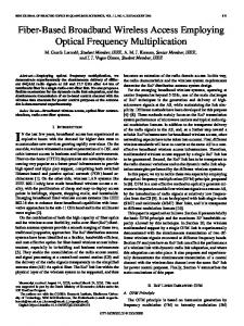
Figure 4. Lagrangian points, picture taken from: wikipedia.org
This experiment was an inter-island test between La Palma and Tenerife done in the year 2007. Over that
11
E. Leitgeb et al.
line of 142 km a distance corresponding to 1,500,000 km was simulated as this is the route from Earth to the Lagrangian point L2 (L1 is as far away, but on the opposite side). On the transmit side, a MOPA (Master Oscillator Power Amplifier) laser was taken, with one Watt transmit power. As modulation scheme, 32-PPM (Pulse Position Modulation) was in use. On Tenerife, the 1m OGS with a Si-APD and a measured sensitivity of -70.9 dBm played the role of the receiver side. Finally, the user data rate was set to 10 Mbps [21]. ROSA study This was again an inter island test between La Palma and Tenerife. Main goal was the investigation of Optical Telemetry for the MSR (Mars Sample Return) mission. During the test a simultaneous presence of atmospheric turbulence and sky radiance was detected. Due to the fact, that the link was over a horizontal line with a length of 142 km, worse conditions compared to a (near) vertical link to space were encountered. The long term link testing provided results for genuine day and night conditions. For this distance, as Mars is up to 400,000,000 km away, only PPM can be used as modulation scheme. Q-switched lasers provide only a low pulse repetition frequency, but very high power in the emitted pulses. Variable PPMs were examined; as a consequence, variable data rates were achieved. The targeted data rate of 1 Mbit/s was not reached due to several reasons. As a conclusion, improvements of the laser technology would lead to the desired data rate [22].
atmospheric conditions mainly determine the reliability and availability of FSO links. Presence of fog is the main important factor that severely attenuates the transmitted optical signal power and thus raises many questions on the carrier grade operation of FSO links. We at TU Graz are investigating the free-space optical signal propagation through the troposphere for broadband terrestrial applications. Within COST 270 and SatNEx programmes, we performed successful fog attenuation measurement campaigns in June 2004 (under dense maritime fog conditions at Nice) and in September 2005 – February 2006 (under moderate continental fog conditions at Graz), to study the deleterious effects of fog [14]. We used self developed FSO systems operating at 850 nm and 950 nm centre wavelengths. Figure 6. & Figure 7. below, show two sample fog events at the above mentioned locations. At Nice, eight dense maritime fog events were observed during the 24 June - 01 July 2004, and at Graz about 23 moderate continental fog episodes having durations at least more than half an hour were measured during the above mentioned period.
Figure 6. Attenuations during a dense fog event at Nice
Figure 5. Area, where ROSA took place, taken from: ROSA Final Presentation, ESTEC, 2nd December 2008, Handouts
IV.
INVESTIGATIONS ON OPTICAL SIGNAL PROPAGATION THROUGH FOG
Fog, sleet, rain, snow, smog, clouds and various kinds of aerosols, variations in temperature etc., affect all the wireless systems. Still a reliable operation and certain acceptable availability are the main issues of this technology. The propagation channel (i.e., troposphere) influences the optical signal propagation significantly in certain atmospheric conditions. Particularly, local
12
Figure 7. Attenuations during a moderate continental fog event at Graz
We further analyse the available measured fog attenuations against the cumulative exceedance probability or CDF exceeded (%) to see how many times a particular value of the specific attenuation exceeded a
ConTEL 2009, ISBN: 978-953-184-131-3
Current Optical Technologies for Wireless Access
certain value. This analysis gives us a complete picture of the overall behaviour of fog attenuations. The corresponding Figure 8. Figure 9. for Nice and Graz are shown next, respectively. From the five months of fog attenuation data of Graz, we observed that attenuations are particularly high in January and lowest in October as we know that the most favourable conditions of fog formation and dissipation are low and high temperatures, respectively. Additionally, we divided all the measured attenuations into four time intervals of six hour each i.e., 00:00-06:00, 06:00-12:00, 12:00-18:00, and 18:00-24:00.
Figure 10. CDF exceeded against specific attenuations for Nice Graz Durnal CDF (%) exceeded monthly 100
00-24 00-06 06-12 12-18 18-24
90 80
CDF exceeded (%)
70 60 50 40 30 20 10 0
Figure 8. CDF exceeded against specific attenuations for Nice
0
20
40 60 80 Specific Attenuation (dB/km)
100
120
Figure 11. CDF exceeded against specific attenuations for Graz 100
We also developed a method of estimating the gamma distribution parameters to model the continental fog attenuations by employing the Mie scattering theory and a modified gamma fog droplet size distribution model. We applied this method on the measured maximum, mean and median values of moderate continental fog attenuations for Graz and Milan. The corresponding plots of estimated specific attenuation values against the fog droplet radius are shown in Figure 12. Figure 13. [16].
90 80
CDF ex ceeded (% )
70 60 50 40 Oct. 2005-Feb.2006 Oct. 2005 Nov. 2005 Dec. 2005 Jan. 2006 Feb. 2006
30 20 10 0
0
20
40
60 80 100 120 Specific Attenuation (dB/km)
140
160
180
Figure 9. CDF exceeded against specific attenuations for Graz
From Figure 10. we observed that for Nice, the attenuations are particularly high during the evening hours (12:00 – 18:00) and are generally low during the morning hours (06:00-12:00 hours). And from Figure 11. it looks obvious that attenuations are particularly high during 18:00-24:00 hours time interval for Graz but show lowest trend during 00:00-06:00 time interval [15].
ConTEL 2009, ISBN: 978-953-184-131-3
Figure 12. Predicted specific attenuations for Graz using MGDSD and Mie scattering
13
E. Leitgeb et al.
is valid when turbulence is near the telescope. In the case of a negative-elevation link, most turbulence can be several hundreds of kilometres away from the HAP. Second, the point-ahead angle separating the incoming and outgoing beams (necessary to track fast-moving satellites) may be larger than the isoplanatic angle. Finally, the sending aperture may not correspond to the receiving aperture. A small coherence diameter r0 can therefore introduce pointing errors. r0 is defined as r0 = 2.1 × ⎡1.45k
⎣
2
∫
L
0
Cn ( z ) dz ⎤ 2
−3 / 5
⎦
[18], where k is related to the wavelength λ by
Figure 13. Predicted specific attenuations for Milan using MGDSD and Mie scattering
k = 2π λ . For λ = 1µm, D = 0.05 m, r0 = 0.25 m, we have σAoA = 1.1 µrad the following graph is calculated (Figure 14. ).
We are further continuing our efforts on modelling the atmospheric channel for FSO links statistically under different fog conditions. Another dimension of our efforts on the better applicability of FSO links for a number of applications in the next generation networks is to get further insight into developing newer FSO channel estimation and equalisation techniques in order to fulfil the reliability, quality of service and availability demands. V.
ATMOSPHERIC TURBULENCES
As mentioned in the former chapters, the atmospheric turbulences also called scintillations have an important influence on Optical Wireless links. Considering a Gaussian beam propagating through the atmosphere, optical turbulence distorts its wave front and spatially redistributes its energy. The Huffnagel-Valley model is a widely-used vertical profile for the turbulence strength parameter Cn2. We consider the so-called HV5/7 model [17] which, for stratospheric heights, can be expressed as: 2
−3
−5
10
C n ( h ) ≈ 3.6 × 10 (10 h ) e
− h / 1000
h < 7 km
h is the altitude in meter. HV5/7 models a moderately turbulent atmosphere. We additionally assume turbulence is isotropic. This is an approximation as measurements in the stratosphere reveal the presence of horizontal turbulence layers [6].We consider here the coherence diameter r0 which determines the Strehl ratio and affects the uplink and the downlink. r0 is relevant for coherentdetection systems which are currently implemented for inter-satellite links [18]. For the uplink, when r0 is on the same order of magnitude as the outgoing-beam radius W0, significant beam wander takes place. When r0 is significantly smaller than W0, a beam-spread effect takes place [17]. For the downlink, angle-of-arrival fluctuations increase as r0 decreases. When r0 is significantly smaller than the receiving aperture diameter D, a great loss occurs in receivers [5]. One may argue through the reciprocity principle that the wander of the outgoing beam can be compensated by tracking the angle of the incoming beam. However, three facts weaken the validity of the reciprocity principle. First, the reciprocity principle
14
Figure 14. Isolines of the coherence diameter r0 calculated for the wavelength λ = 1µm and with the model HV5/7.
To counteract the turbulence effects diversity methods (like TX and RX diversity, aperture averaging, adaptive optics and MIMO techniques) are used. VI.
ACHIEVED IMPPROVEMENTS
The main focus is the reliability of optical components and devices in communications networks and systems (where free space laser communications is included). In COST 270 and SatNEx a lot of scientific missions have been carried out for FSO. The main work in this field is to increase the channel capacity, reliability and availability of Optical Wireless links and its combination with microwave links [2] is an important part of the “next generation” future network. A. Hybrid System with high availability It is obvious that optical communication links, due to their high carrier frequencies in the range of 300 THz allow very high data rates compared to all other communications media. This is clearly shown by the fibre optic communication industry that started development more than three decades ago. But the line of free propagation of light through the atmosphere is tremendously influenced by dense fog.
ConTEL 2009, ISBN: 978-953-184-131-3
Current Optical Technologies for Wireless Access
Microwave links below about five GHz are mainly affected by other microwave systems and by rain and they are restricted by limited bandwidth, especially in the licence-free bands, The main influence on FSO systems is dense fog as mentioned above; therefore a combination with LMDS (40 GHz microwave) was evaluated at TU Graz. We are also trying to develop a hybrid switch-over between FSO and mmW links and to-date we have achieved significantly fruitful results towards its realisation. The hybrid system combines the advantages of the microwave and optical links regarding the availability at specific weather conditions. During the measurements snowfall, fog and rain occurred, which is visible in the low availability of both links, the result is drawn in Figure 15. for each month. Nevertheless, the hybrid has very high availability. This can be seen as proof, that the systems have orthogonal behaviour [19].
are often selected in combination with the modulation format, in order to achieve better gains, and the PPM signalling scheme seems to lend itself naturally to a Reed Solomon code, whose alphabet size can be easily matched to the PPM order. This results in a one-to-one correspondence between RS code symbols and PPM symbols. Since every RS code is a maximum distance code, it appears that no more powerful code could be found for this application. There have been proposals for combining Turbo codes with PPM primarily because of their higher coding gains and their ability to utilise soft outputs. Further investigations into the design of the channel codes to suit the FSO channel and to combine well with the pulse position modulation are being carried out and may lead to some more interesting results. Simulation was done by TU Graz and IJS within SatNEx. In a scientific research mission TU Graz and IJS simulated the performance curves for M-ary PPM with two different values for M, namely 16 and 256 (see Figure 16. ). As perceived by the theoretical analysis that higher state PPM with more concentrated but same average power shall perform better, was proved correct. The 256-PPM showed an improvement of about 13 dB at a BER of 10-6 over the 16-PPM curves under the ambient light conditions. The Reed Solomon RS (255; 127) codes in combination with 16-PPM provided 6 dB of coding gain. This indicates that the sensitivity of the receiver can be improved by 6 dB using RS codes. According to the investigations done in Graz [2], the scintillation fades were measured at 4 dB; this shows that RS codes alone can combat such scintillation fades.
Figure 15. Availability of the separate links and the hybrid
These initial measurements have been used to analyse bandwidth efficient switch over for two links. The simulation results show that bandwidth efficient implementation can avoid more than 90% redundant usage of microwave, provided that switching is fast enough to avoid any link availability reduction. The so liberated resources of the microwave system can be used for useful information transfer [14]. B. Modulation and Coding in FSO Most of the FSO systems being currently used employ the intensity modulation with direct detection scheme (IM/DD). Previous investigations have shown that deep fog is the most severe deterrent. Hence, penetration of light has to be improved for example by concentrating more power into lesser areas. This indicates towards the utilization of power efficient modulation schemes. With the emphasis on the average power requirements M-PPM is an attractive modulation scheme, and in principle, the optical power requirements can be made arbitrarily small by making M suitably large, at the expense of increased bandwidth [20]. The channel codes
ConTEL 2009, ISBN: 978-953-184-131-3
Figure 16. Performance curves for RS-coded PPM
This opens up possibilities of achieving appreciable coding gains by using concatenated codes employing an outer block and inner convolutional code, with matched interleaver. We conclude through the investigations, that coded higher state PPM modulation can provide considerable gains and thus performance enhancement for the terrestrial FSO systems. Long fades can be combated with matched interleaver concatenated coding.
15
E. Leitgeb et al.
TABLE I.
VII.
OPTICAL PARAMETERS OF EXPERIMENTAL CONFIGURATION FOR OPTICAL LINKS
CONCLUSIONS
Optical Wireless is an excellent nomadic broadband solution (high bandwidth) for connecting the backbone to the users (Last-Mile-Access). This technology should be understood as supplement to conventional radio links and Fibre Optics. The use of cheaper FSO systems for short distances makes this technology more interesting for private clients whereas the long distance links are the more sophisticated and expensive solution. But in both cases fog and clouds in the troposphere are the most limiting factors. At the moment the main work in this field is to increase reliability and availability. These two parameters of an FSO link are mainly determined by the local atmospheric conditions. Therefore good reliability and availability can be achieved by using the FSO for short distances, by incorporating enough link budget margin and by using the optimal network architecture for each FSO application. The combination of FSO and microwave links demonstrates a possible solution for increasing reliability and availability, because terrestrial FSO is mostly influenced by fog, whereas the microwave propagation is mainly influenced by rain. In that case wireless hybrid (optical & microwave) links have been evaluated at the Department of Communications and Wave Propagation. Results in [19] show a reliability of 99.9991 % of such a hybrid system.
16
The best solution for FSO configurations will be a meshed network. This architecture combines shorter distances and high reliability, because of the location of the Optical Multipoint Unit (in the centre of the area). Also are mentioned some very latest interesting and important optical wireless experiments for ground-space link scenarios showing the importance of this technology for the next generation access networks. In order to increase the wide acceptability of this communication technology world wide, reliability and availability enhancements are of prime importance. Therefore, it is necessary to make field tests on FSO systems in regard to the local atmospheric conditions. Therefore reliability and availability tests are running within COST and SatNEx. Models for propagation and for predicting link availability in different climate zones will improve the installation of this optical wireless technology. VIII. REFERENCES [1] [2]
[3]
A. K. Majumdar, J. C. Ricklin. “Free-Space Laser Communications, Principles and advantages”, Springer Science LLC, 2008. E. Leitgeb, S. Sheikh Muhammad, Ch. Chlestil, M. Gebhart, U. Birnbacher, “Reliability of FSO Links in Next Generation Optical Networks”, Proceedings and Invited Presentation at the IEEEconference ICTON 2005, 3rd – 7th of Juliy2005, Barcelona. E. Leitgeb, M. Gebhart, U. Birnbacher, “Optical Networks, Last Mile Access and Applications”, Book-Chapter of “Free-Space Laser Communications: Principles and Advances”, (accepted 2004, published 2008), Springer Verlag, ISBN: 978-0-387-286525.
ConTEL 2009, ISBN: 978-953-184-131-3
Current Optical Technologies for Wireless Access
[4] [5]
[6]
[7] [8]
[9]
[10] [11]
[12]
[13]
N. Perlot, “Turbulence-induced fading probability in coherent optical communication through the atmosphere", Appl. Opt. 46, 7218-7226 (2007). J. Horwath, N. Perlot, M. Knapek, and F. Moll, “Experimental Verification of Optical Backhaul Links for High-Altitude Platform Networks: Atmospheric Turbulence and Downlink Availability”, International Journal of Satellite Communications and Networking, Special Issue (2007). S. Betti, V. Carrozzo, E. Duca,”Over-Stratospheric-Altitude Optical Free Space Links: System Performance Evaluation Transparent Optical Networks”, in ICTON, International Conference on Transparent Optical Networks, July 2007. A. Alonso, et al., “Performance of satellite-to-groundcommunications link between ARTEMIS and the Optical Ground Station”, Proc. SPIE, Vol. 5572, 372 (2004). Williams, W. et al., “RF and Optical Communications: A Comparison of High Data Rate Returns From Deep Space in the 2020 Timeframe”, NASA/TM—2007-214459, 2007. Ortiz, G.G. et al, “Design and development of robust ATP subsystem for the Altair UAV-to-ground lasercomm 2.5-Gbps demonstration”, Proceedings of the SPIE Vol. 4975, 2003. Horwath, J. et al., “Broadband Backhaul Communication forStratospheric Platforms: The Stratospheric Optical Payload Experiment (STROPEX)”. Cazaubiel, V. et al., “Le terminal optique aeroporte sur lola”, Proceedings of OPTRO 2005 Conference, Paris, France, May 2005 Perlot, N. et al, “Results of the Optical Downlink Experiment KIODO from OICETS Satellite to Optical Ground Station Oberpfaffenhofen (OGSOP)”, Proceedings of SPIE, Vol. 6457, 2007. Horwath, J. et al., “Coherent Transmission Feasibility Analysis”, Proceedings Free-space laser communication technologies XVII, San Jose CA, 25-26, January 2005.
ConTEL 2009, ISBN: 978-953-184-131-3
[14] B. Flecker, C. Chlestil, E. Leitgeb, S. Sheikh Muhammad, M. Gebhart, “Results of Attenuation Measurements for Optical Wireless Channels under Dense Fog Conditions”, Proceedings and Presentation at the SPIE Optics and Photonics Symposium, San Diego, USA, August, 2006. [15] M. S. Awan, E. Leitgeb, C. Capsoni et al. “Evaluation of Fog Attenuations Results for Optical Wireless Links in Free Space”, IWSSC 2008, pp. 112-116, Toulouse, France, 1-3 October 2008. [16] M. S. Awan, E. Leitgeb et al. “Distribution Function for Continental and Maritime Fog Environments for Optical Wireless Communication”, CSNDSP 2008, pp. 260-264, Graz, Austria, 2325 July 2008. [17] L. Andrews, R. Phillips, “Laser Beam Propagation through Random Media, 2nd Edition”, SPIE Press, Bellingham, WA, (2005). [18] R. Lange, B. Smutny, ”Homodyne BPSK-based optical intersatellite communication links”, Proc. SPIE 6457, 645703 (2007). [19] E. Leitgeb, M. Gebhart, U. Birnbacher, W. Kogler, P. Schrotter, “High availability of hybrid wireless networks”, Proceedings and Presentation at SPIE's International Symposium Photonics Europe, Vol. 5465, pp. 238-249, 26th - 30th April 2004, Straßburg. [20] S. Sheikh Muhammad, T. Javornik, I. Jelovcan, Z. Ghassemlooy and E. Leitgeb, “Comparison of hard-decision and soft-decision channel coded M-ary PPM performance over free space optical links”, European Transactions on Telecommunications (2008), DOI 10.1002/ett.1343. [21] G. Baister, K. Kudielka, T. Dreischer, M. Tüchler, “Results from the DOLCE (Deep Space Optical Link Communications Experiment) Project”, Proc. of SPIE Vol. 7199 71990B-1 [22] T. Dreischer, “ROSA Final Presentation (RF-Optical System Study for Aurora)”, ESA Contract No. 20371/07/NL/EK Final Presentation, ESTEC, 2nd December 2008
17
This page intentionally left blank.
18