Medical Image Analysis 7 (2003) 475–488 www.elsevier.com / locate / media
Deformable biomechanical models: Application to 4D cardiac image analysis M. Sermesant*, C. Forest, X. Pennec, H. Delingette, N. Ayache Epidaure Project, INRIA Sophia-Antipolis, 2004 Route des Lucioles, BP 93, 06902 Sophia-Antipolis, France
Abstract This article describes a methodology for creating a generic volumetric biomechanical model from different image modalities and segmenting time series of medical images using this model. The construction of such a generic model consists of three stages: geometric meshing, non-rigid deformation of the mesh in images of various modalities, and image-to-mesh information mapping through rasterization. The non-rigid deformation stage, which relies on a combination of global and local deformations, can then be used to segment time series of images, e.g. cine MRI or gated SPECT cardiac images. We believe that this type of deformable biomechanical model can play an important role in the extraction of useful quantitative local parameters of cardiac function. The biomechanical model of the heart will be coupled with an electrical model of another collaborative project in order to simulate and analyze a larger class of pathologies. 2003 Elsevier B.V. All rights reserved. Keywords: Biomechanical model; Tetrahedral mesh; Finite element method; Deformable model; Image analysis; Cardiac motion
1. Introduction In the past few years, deformable biomechanical models have proven to be relevant in many different areas of medical informatics (Fig. 1). First, they have been used in the field of computational biomechanics in order to understand or predict the deformation of anatomical structures (Payan et al., 2002; Azar et al., 2002). Furthermore, these models can be validated by comparing predicted and observed deformations in medical images (Kerdok et al., 2001), owing to their unique ability to observe in vivo deformations. More recently, the simulation of therapeutic procedures, and especially surgical procedures, has required the development of real-time soft tissue models (Picinbono et al., 2001) combined with visual and haptic feedback (Picinbono et al., 2000). Also, by including physiological information in a biomechanical model (Sermesant et al., 2002a), one can obtain a better understanding of the pathology. Finally, since they capture a priori knowledge concerning tissue deformation, these models are well suited for the tracking of structures in time series of medical images. *Corresponding author. E-mail address:
[email protected] (M. Sermesant). 1361-8415 / 03 / $ – see front matter 2003 Elsevier B.V. All rights reserved. doi:10.1016 / S1361-8415(03)00068-9
In this article, we focus mainly on the construction of deformable biomechanical models in the scope of image analysis and more precisely of cardiac image segmentation. Several segmentation techniques have been proposed in the literature, most of them relying on surface-based deformable models (Frangi et al., 2001). Only a few teams
Fig. 1. Deformable biomechanical models are related to many different topics. (This figure is available in colour, see the on-line version.)
476
M. Sermesant et al. / Medical Image Analysis 7 (2003) 475–488
Fig. 2. The three different stages of biomechanical model construction: mesh creation, mesh registration to a 3D image and information retrieval. The model is then used for image segmentation. (This figure is available in colour, see the on-line version.)
(Papademetris et al., 2001; Pham et al., 2001) have developed a volumetric biomechanical model for segmenting and tracking the cardiac ventricles, claiming that it offers more reliable estimations of quantitative measurements (strain, stress, etc.). Different types of information can be included in such a model, for instance muscle fiber directions in a cardiac image analysis application (Papademetris et al., 2001; Sitek et al., 2002). Moreover, there are different ways to use biomechanically controlled meshes. They are generally used to physically interpolate deformations in a volumetric mesh from imposed displacements on the surface nodes (Ferrant et al., 2000; Hagemann et al., 2000; Azar et al., 2002; Skrinjar et al., 2002; Davatzikos et al., 2001). However, by imposing displacements, the authors propose the hypothesis that the matching between surface nodes and image boundary points is correct. In this case, the biomechanical model serves mainly to regularize the position of the internal nodes of the mesh. In our approach, external constraints are posed in terms of applied forces. Consequently, the biomechanical material property has a direct influence on the deformation process and therefore on the segmentation outcome. Moreover, the segmentation method presented in this article relies on the deformable model framework defined on a volumetric tetrahedral mesh. The internal energy is defined as a transverse anisotropic, piecewise linear elastic energy, whereas the external energy is based on a region approach, including intensity and gradient information. Each volumetric mesh includes the anatomical and mechanical properties specific to a given anatomical structure, which improves the robustness of the segmentation process. To create a volumetric biomechanical model, a boot-
strapping approach is employed (Fig. 2). We start with a geometric tetrahedral mesh of an anatomical structure, possibly created from a closed triangulated surface. Then, we register this raw model to different image modalities (such as diffusion tensor imaging, MR imaging or histology reconstruction) to retrieve important anatomical, functional or biomechanical information (fiber directions, Young modulus, anatomical regions, etc.). These pieces of information are fed to the model and used for the next registration stage. Finally, when all necessary information has been retrieved, the complete model can be used to perform image segmentation or tracking. Each part of the process is illustrated with examples related to cardiac image analysis: a biomechanical model of the heart is constructed, it is fitted to different cardiac imaging modalities, then the information is assigned from the images to the mesh and, finally, it is used to track the cardiac motion in 4D image sequences. Preliminary results for the quantitative parameters of cardiac function are presented in Section 6.
2. Mesh creation We chose to create a volumetric mesh of the heart that includes both right and left ventricles (RV and LV, respectively). Many image modalities have a field of view large enough to include both ventricles. Furthermore, the right ventricle motion also provides clinically relevant information. We chose to use a geometric representation based on tetrahedra rather than hexahedra (as suggested in (McCulloch et al., 1998)) in order to better capture the finer geometric details of the RV and LV during the image
M. Sermesant et al. / Medical Image Analysis 7 (2003) 475–488
477
Fig. 3. Posterior and basal view of the constructed left and right ventricle myocardium tetrahedral mesh. (This figure is available in colour, see the on-line version.)
segmentation stage (Fig. 3). Moreover, tetrahedral meshes make it possible to perform local mesh refinement in a straightforward manner, whereas more sophisticated hierarchical adaptive refinements of basis functions are required to achieve the same results on hexahedral meshes. Finally, tetrahedra allow for analytical computations of stiffness matrices, whereas hexahedra necessitate numerical Gaussian integration. This yields significantly shorter computation times, which is a necessity when working in the deformable model framework. However, it is widely accepted that hexahedral finite elements are better suited than tetrahedral elements for the deformation computation of incompressible materials. When creating a tetrahedral mesh, we must take two parameters into account. First, the mesh size should be small enough in order to keep the computation time compatible with user interaction. Second, the shape quality of the tetrahedra must be sufficiently high to produce accurate results. We approach both issues as a process of first creating a triangular mesh, before generating a tetrahedral mesh from it. A number of low-level tasks were used to construct a triangular mesh of the ventricles: image segmentation, morphological operations, image smoothing, connected component extraction, isosurfacing and mesh decimation. The quality of the triangular elements and their sampling (increased in parts of high curvature) was controlled visually. The tetrahedral mesh was generated from this triangular shell using the commercial software GHS3D,1 developed at INRIA. The resulting mesh has 2000 vertices and 10 000 tetrahedra.
3. Mesh registration: fitting to the 3D image Registration of our biomechanical heart model to a given image modality is necessary in order to fuse multiple information in the same volumetric model. This stage is also a prerequisite before the segmentation and tracking 1
http: / / www-rocq.inria.fr / gamma / ghs3d / ghs.html.
steps in image modality (MR, 3D US or functional imaging) used clinically. This registration stage must not only be robust but also fairly efficient since it is part of the interactive segmentation software. Consequently, non-rigid registration was performed via the coarse-to-fine approach proposed by Montagnat and Delingette (1998). This smoothly combines registration and a deformable model framework. At a coarse scale, an Iterative Closest Point (Besl and McKay, 1992) type of algorithm is applied with, successively, a rigid, similarity and affine transformation (see Section 3.2). At a fine scale, the minimization of the internal and external energy permits more local deformations (see Section 3.3). For both methods, the closest boundary point to each mesh vertex must be determined. Another method used to adapt a mesh to a specific image, using a non-rigid registration algorithm, can be found in (Castellano-Smith et al., 2001).
3.1. Closest boundary points computation A few authors (see Frangi et al., 2001) have proposed techniques to segment myocardium images using a volumetric model. They often rely on interactive segmentation (Papademetris et al., 2001; Schulte et al., 2001) or precomputed distance maps (Pham et al., 2001) to define the boundary attracting force driving their models. In our approach, the computation of this force at a surface vertex depends not only on the vertex location but also on its normal direction. Different types of forces may be applied depending on the image modality. We chose to combine intensity and gradient information with a region-based approach (Montagnat et al., 2003) applied to the intensity profile extracted at each vertex along its normal direction. It consists of defining a region with a range of intensity values and then finding its boundary by looking at the voxels of high gradient values. The extent of the intensity profile is decreased in the coarse-to-fine process (Fig. 4). Since there are often occlusions or very noisy parts (for example, the right ventricle may not be visible or may have a much reduced intensity due to intensity shading
M. Sermesant et al. / Medical Image Analysis 7 (2003) 475–488
478
Fig. 4. Red lines: matching between surface nodes of the mesh and closest boundary points in the image. Each surface node of the mesh looks for a high gradient voxel in a given intensity and distance range, along its normal direction. (This figure is available in colour, see the on-line version.)
effects), we set the extent of the image interaction (external force) to different values depending on the anatomical regions of our model (determined in Section 4): parts which are not seen in the image do not then contribute to the external energy.
3.2. Global transformation computation The initial alignment is given by the correspondence of the image and model axes and a rough superimposition of the ventricles. Then, one iteratively estimates the point matches (with the method described in the previous section) and the best transformation defined by these matchings, in an Iterative Closest Point-like loop. A rigid transformation is first estimated using the standard leastsquares criterion. After convergence, the transformation model is enriched with a scale factor (similarity) and later upgraded to a full affine transformation model. A problem we observed with standard least-squares similarity and affine estimations in such an iterative loop with real data (like MRI) is that the global minimum is reached when all model points are matched to the same image point, even if the transformation is singular (null determinant of the linear part). The error is then null (thus minimized!). To avoid this problem, we have defined a new affine registration criterion C which is symmetric and ‘‘invariant’’ with respect to the action of an affine transformation to both the model and the image data. This feature effectively prevents the criterion from leading to a singular affine transformation. Let m i and d i be the matched model and image data points, A the affine transformation and t the translation. The criterion to minimize is
O(Am 1 t 2 d ) (Id 1 A A) t
C(A,t) 5
i
i
t
(21)
Gaussian noise, we have the following statistical model: m i 5 e i 1 ei and d i 5 Ae i 1 t 1 ni with ei . ni . N(0,s 2 ). Then, a maximum likelihood (ML) estimation of the exact points (knowing the transformation) gives the closed form solution e i 5 (Id 1 At A)(21) (m i 1 At (d i 2 t)). Substituting for this value in the ML criterion finally leads to the above registration criterion. Like standard least-squares, this criterion has a closed form solution for the transformation: ¯ )t ;(d i 2 d¯ )t ] be the horizontal vector of • let h ti 5 [(m i 2 m the joint barycentric coordinates of the model points and the image data points; • let l1 < ? ? ? < l6 be the sorted eigenvalues of the symmetric matrix o i h ti < hi , and [L t1 ;L t2 ] 5 [ x1 , x2 , x3 ] t be the 336 matrix constituted by the first 3 eigenvectors. t Then, the optimal linear transformation is Aˆ 5 2 L 2t 2 L1 and • Aˆ exists if and only if L2 is invertible; • Aˆ is unique if and only if l3 , l4 . ˆ¯ The optimal translation is given, as usual, by tˆ 5 d¯ 2 Am. This criterion is easily adapted to the similarity case with A 5 sR and one can show that the rotation and translation are similar to the rigid case. However, the scale estimation is different from the least-squares and Procrustes ones (where the scale is the ratio of the inertia of the two point clouds): it is symmetric (like the Procrustes method (Goodall, 1991)), but takes into account the individual matches and not just the global properties of the point sets. This criterion makes it possible to adequately initialize the model with a global transformation even in noisy images. The model can then be fitted with better accuracy using local deformations.
(Am i 1 t 2 d i ).
i
This criterion can be derived from the following statistical formulation (Pennec, 2003). Let us assume that both the model points m i are noisy measurements of an unknown but exact set of points e i and that the image data points d i are noisy measurements of a transformed version of the same set of exact points. Taking an isotropic and stationary
3.3. Local deformation computation At this stage, our biomechanical model evolves under the influence of both an Internal Energy computed from the physical properties of the organ and an External Energy computed from the image, as defined in the deformable model framework.
M. Sermesant et al. / Medical Image Analysis 7 (2003) 475–488
3.3.1. Internal energy The internal energy is computed with linear elasticity using a Tensor-Mass model (Cotin et al., 2000). We use a Finite Element Method with linear tetrahedral elements and mass-lumping in a Newtonian differential equation with an explicit time integration scheme. There are two different cases for local deformation: • General Heart Model to Patient Dataset. There is no physical basis for the deformation when fitting our general model of the heart to an image from a given dataset. Therefore, we use isotropic elasticity with small Lame´ constants to allow greater deformations. • Multi-modality Registration. If we want to adapt a given heart model to another image of the same heart, we use (anisotropic) linear elasticity with Lame´ constants, as it physically corresponds to a deformation of the myocardium. We may also use the anatomical region information from the model to better control the internal energy by taking different Lame´ constants for different anatomical regions (fat, ischemic zones, etc.). 3.3.1.1. Preconditioning the Tensor-Mass model. As we need a fast deformable model to be able to control it visually, we use a preconditioning that increases the convergence speed. The Courant condition, which gives an upper limit of the time step tc to ensure stability in an explicit time integration, is given by ]] r tc , l ]], l 1 2m
œ
where l is the minimal edge length of the mesh, r the mass density and l and m the Lame´ constants. Therefore, the time step can become very small for some organs with large Lame´ constants. To obtain fast deformable models, we propose a preconditioning of the stiffness matrix that ensures the stability of the process with greater time steps. It only affects the dynamic of the deformation convergence, not the final match. The idea is to multiply the diagonal blocks by their inverse to ensure that the eigenvalues of the preconditioned matrix belong to [21;1]. Thus the time step does not depend on the Lame´ constants. To
479
obtain this, each block line of the stiffness matrix is multiplied by the inverse of the diagonal block of the same line.
3.3.2. External energy At each step of the deformation, the forces are applied on the surface nodes of the model with a direction normal to the surface at that point and an intensity proportional to the distance to the match point. The a priori information used is the intensity profile of the boundaries we want to match on these points, as the points of the mesh we want to match with the image are on the surface of the model. 3.4. Application: model fitting to 3 D cardiac images 3.4.1. Myocardium 3 D image of the visible human A first experiment consisted of fitting a canine heart model extracted from DTI to the human heart image of the Visible Human Project (VHP, see Fig. 5). The goal was to use this segmented VHP heart image to define the anatomical regions in the heart model mesh. Although the rotation between the initial mesh and the data was quite large, and despite an actual inter-species fitting (a canine heart mesh to a human case), the rigid-to-affine-to-local transformation sequence allowed us to perform the registration and gave a qualitatively good segmentation of the myocardium. 3.4.2. 3 D MRI of human heart We then experimented with the fitting of the same canine model to a human cardiac MRI. The similarity and the affine transformations could not be computed with the classical least-squares criterion and we had to use the new criterion presented in Section 3.2. As the right ventricle was very noisy in this image, we only used regions where the myocardium was visible to compute the external forces. MR images are intensity shaded, and as a result the intensity was greater in the apex than around the base in some sequences. Automatic segmentation of the myocardium in MRI is rather difficult and the presented method gave qualitatively good results (cf. Fig. 6). The fitting of the model in a 3D image takes around 30 s
Fig. 5. Fitting of a canine heart model to the Visible Human heart image. Blue: before deformation; green: after deformation. The rotation was correctly ¨ recovered and this inter-species registration gave good results (VHP data courtesy of Pr. Hohne et al.). (This figure is available in colour, see the on-line version.)
480
M. Sermesant et al. / Medical Image Analysis 7 (2003) 475–488
Fig. 6. Fitting of a canine heart model to a human MRI. Blue: initial mesh; green: after deformation. Even in the case of very sparse data in the long axis dimension, the biomechanical model gives good results. (This figure is available in colour, see the on-line version.)
on a standard PC with a 10 000 tetrahedra mesh (due to the anisotropy of the MRI voxels, a finer mesh would not be useful, as the information is very sparse in the z direction). It is then fast enough to allow interactive control.
voxel centers. Let Vx , Vy and Vz be the voxel sizes in the x, y and z (horizontal) directions and a, b and g the integer indices of the voxels in the corresponding directions:
4. Information assignment
1 Pg : Zg 5 g 1 ] Vz . 2
To construct a useful biomechanical model, we need to feed the geometric model with anatomical (and functional) information, originating from different image modalities. This information may be quantitative, when extracted from medical images, or qualitative (semantic), when extracted from precisely segmented anatomical atlases. Furthermore, this information may be stored at the vertex or at the tetrahedron level, depending on the way it is used. Vertex information can easily be interpolated from the image values by a trilinear or nearest-neighbor algorithm (for quantitative or qualitative parameters, respectively). However, in a Finite Element approach, many attributes are stored in each element (tetrahedron) and not in vertices. To extract the element value from the image, we need to find for each tetrahedron of the mesh its corresponding voxels in the volumetric image: this is called the rasterization stage. Rasterization is an old problem, well known in computer graphics: it consists of converting a vertex representation into a pixel representation. The idea is to find, for each tetrahedron, the image voxels whose center points are located inside this tetrahedron, and then assign it either the median or the average value (depending of the signal-to-noise ratio of the information stored in the voxels). It would certainly be more accurate to have, for each tetrahedron, the list of intersecting voxels and, for each of them, the volume actually intersected. This process would be similar to the anti-aliasing process in computer graphics and such a result is more complicated to retrieve. When the tetrahedra are large enough with respect to the size of the voxels, we believe that this ‘‘first degree approximation’’ is satisfactory. The set of voxels whose centers belong to a given tetrahedron is found in the following way. • First, we consider the intersection of that tetrahedron with each of the horizontal planes Pz located at the
S
D
The intersection between the tetrahedron and a horizontal plane is a convex polygon whose vertices are composed, for one part, of the tetrahedron vertices located exactly on the plane and, for the other part, of the intersection of the tetrahedron edges composed of one vertex located above the plane and the other located below. All the voxels whose center belongs to one of these polygons are located inside the tetrahedron (Fig. 7). • The polygons are then intersected with horizontal lines lg, b located on voxel centers:
lg, b
S S
D D
1 Zg 5 g 1 ] Vz 2 : 1 Yb 5 b 1 ] Vy . 2
The intersection are line segments [(Xmin ,Yb ,Zg ),(Xmax ,Yb ,Zg )],
Fig. 7. Rasterization process: determining the voxels inside a given tetrahedron using the intersection with horizontal planes. (This figure is available in colour, see the on-line version.)
M. Sermesant et al. / Medical Image Analysis 7 (2003) 475–488
481
Fig. 8. Voronoı¨ diagram of the anatomical areas. Left: one slice of the initial image; right: corresponding diagram of the same slice. (This figure is available in colour, see the on-line version.)
where Xhmin,maxj 5 hArgmin, Argmaxj ((Xa ,Ya ),(Xb ,Yb ))
S
D
Yb 2 Ya 3 Xa 1 ]](Xb 2 Xa ) , Yb 2 Ya
X1 2 X0 Xg 11 5 Xg 1 ]]], Z1 2 Z0 Y1 2 Y0 Yg 11 5 Yg 1 ]]], Z1 2 Z0 Zg 11 5 Zg 1 1.
where (Xa ,Ya ) and (Xb ,Yb ) are pairs of vertices of the intersected polygon. All voxels whose centers belong to one of these segments are then located inside the tetrahedron. • The segments are then intersected with the voxel centers. Therefore, if the origin of the tetrahedra coordinates coincides with the front lower left corner of the image, then the corresponding voxels are in the segment [(amin , b,g ),(amax , b,g )], Xhmin,maxj 1 with a(min,max) 5 ]]] 2 ]. Vx 2 The intersection of the tetrahedron (or polygon) edges with the planes is computed using an incremental scheme inspired from Bresenham’s algorithm (Bresenham, 1965) which is much more efficient than direct computation. The idea of this scheme is really simple: if [(X0 ,Y0 ,Z0 ),(X1 ,Y1 ,Z1 )] is one of the edges of the tetrahedron and if (Xg ,Yg ,Zg ) is the intersection of that edge with the plane Pg , then the intersection of that edge with the following plane (Pg 11 ) can readily be computed by
A similar method can be applied for the polygon edges. Once the information has been assigned to the mesh, and the mesh deformed to another modality, we can use an inverse process to generate an image from the values stored in the mesh and the deformation computed. This can be seen as a multi-modality image registration through a mesh. However, we focus only on the direct method in this article.
4.1. Application: anatomical data assigned from images to the heart model For the biomechanical model of the heart we build, we need muscle fiber directions, as they influence the mechanical behavior of the heart, and anatomical areas to better control the deformation and visualize the results of the segmentation.
4.1.1. Voronoı¨ diagrams Before transferring the regions from the image to the mesh by the rasterization process described above, we compute 3D Voronoı¨ diagrams of the values to be read in
Fig. 9. Three slices from a 3D diffusion tensor MRI representing the muscle fiber directions (DTI data courtesy of Dr. Hsu et al.). (This figure is available in colour, see the on-line version.)
482
M. Sermesant et al. / Medical Image Analysis 7 (2003) 475–488
Fig. 10. Fiber directions assigned to the myocardium mesh. (This figure is available in colour, see the on-line version.)
¨ Fig. 11. Three slices of the 3D myocardium segmentation image of the Visible Human Project (segmented data courtesy of Pr. Hohne et al.). (This figure is available in colour, see the on-line version.)
Fig. 12. Anatomical areas assigned to the myocardium mesh from the myocardium segmentation of the Visible Human Project. (This figure is available in colour, see the on-line version.)
the images, to guarantee that even the elements which are not registered to any part of the image that contains information (if the accuracy of the registration is not good enough) will be assigned the closest corresponding value (Fig. 8).
4.1.2. Muscle fiber directions Muscle fiber directions (Fig. 9) can be obtained through Diffusion Tensor Imaging (DTI) (Hsu and Henriquez, 2001). As we want to use these directions for the mechanical elastic anisotropy, we need one direction per
element. DTI is quite noisy, so we choose as direction the mean value of all the voxels in a given tetrahedron. Fig. 10 presents the fiber directions assigned to the mesh.
4.1.3. Anatomical zones A precisely segmented human myocardium is available from the Visible Human Project (Pommert et al., 2001) (Fig. 11). We used this segmentation to define the different anatomical parts of our myocardium mesh. Fig. 12 presents these anatomical zones once assigned to the mesh.
M. Sermesant et al. / Medical Image Analysis 7 (2003) 475–488
483
Fig. 13. Tracking the left ventricle in a 4D SPECT sequence. Top: view along the Z plane; bottom: view along the Y plane. (This figure is available in colour, see the on-line version.)
5. Motion tracking in 4D images using deformable biomechanical models Once the model has been fitted to the first image of the time sequence, we can start the motion tracking, using the position of the model fitted to the previous image as the new rest position. Usually, only local deformations are used to segment an image from the previous image position. But, in some cases, it appears that global transformation iterations using the method presented in Section 3.2 are necessary to obtain good results. This may be because of the global motion of the segmented organ, due to breathing, for example.
5.1. Application: heart motion tracking in 4 D cardiac images 5.1.1. SPECT sequence We segmented a 8*(64364364) voxels SPECT sequence in which the right ventricle was not visible. Two approaches can be used: thanks to the anatomical zones stored into our biomechanical model, we may still use the whole model but set the interaction of the right ventricle regions with the image to zero. Or we can build a mesh of only the left ventricle. We chose here to present the second option. The segmentation results are qualitatively good (see Fig. 13), except in the lower left part of the second row, where the black circular mask applied to the images created a rather high gradient due to the intensity difference between
the mask and the visible parts of the right ventricle. However, this artifact should not appear in the original images and we can use the mesh including both ventricles (as stated previously, this problem may also be avoided by not using the image information locally and relying only on the mechanical regularization).
5.2. Black blood MRI sequence We also used our approach to segment a cardiac 5*(256325639) voxels MRI sequence with the whole heart biomechanical model constructed from the DTI data. In this Black Blood sequence, the myocardium is bright and the blood is dark. Even in a sparse and noisy image like this MRI sequence, the automatic segmentation of the myocardium gives qualitatively good results (see Fig. 14). When a dimension is very sparse, it is important to have a material stiff enough to ensure a smooth surface for the model. Perhaps an additive anisotropy stiffness could be added in this direction to prevent a ‘‘staircase’’ effect, but still allow deformations.
5.3. Balanced fast field echo MRI sequence We also segmented a more recent MR sequence from Philips Medical Systems, produced with Balanced Fast Field Echo and containing 15*(2563256318) voxels images. In this sequence, the blood is bright and the myocardium is dark.
Fig. 14. Tracking of the myocardium in a 5 image MRI sequence. Top: view along the Z plane; bottom: view along the Y plane. (This figure is available in colour, see the on-line version.)
484
M. Sermesant et al. / Medical Image Analysis 7 (2003) 475–488
Fig. 15. Tracking of the myocardium in a 15 image Balanced FFE MRI sequence. Top: view along the Z plane; bottom: view along the Y plane (only 5 instants are presented). (This figure is available in colour, see the on-line version.)
We used for this sequence another deformable biomechanical model of the heart built from dissection data of the Bioengineering Laboratory of Peter Hunter at Auckland University, New Zealand, and smoothed and refined in the Bioengineering Laboratory of Andrew McCulloch at the University of California, San Diego, United States. As the epicardium is hardly visible in this sequence (Fig. 15), we mainly adjusted image force parameters to the endocardium. We also assigned different parameters to the areas corresponding to the epicardium to adapt it to the smaller gradient there, but with a smaller influence (there is a scaling factor for the external and internal energies for each anatomical part). The model data have a very thick myocardium, so the results could be improved with an initial model more in a tele-diastolic shape, with a thinner myocardium. But the tracking of the endocardium gives rather good results, even with the presence of the pillars. The right ventricle shape is difficult to capture, especially around the base, due to the valves.
6. Quantitative parameters (preliminary results) Segmenting images with deformable biomechanical models makes it possible to quantify different cardiac function parameters.
6.1. SPECT sequence We can define the endocardium on the model mesh and then compute the volume defined by this surface (closed by the barycenter of its edge) (see Fig. 16). Then we can compute the ejection fraction (EF): Vend diastole 2Vend systole EF 5 ]]]]]]. Vend diastole For this image sequence, we obtained EF551%, which is close to the normal values, and this is a normal case. To evaluate the right ejection fraction, we must have the maximum and minimum volumes in the sequence. If the
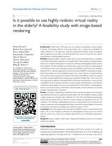
Fig. 16. Left ventricle volume evolution during the 8 SPECT image time sequence and the left ventricle mesh used. The basal lines represent the surface enclosing the endocardium and the long axis line is the inertia axis of the left ventricle used to compute axial and circumferential strains. (This figure is available in colour, see the on-line version.)
M. Sermesant et al. / Medical Image Analysis 7 (2003) 475–488
485
Fig. 17. Radial strain of the model during the heart cycle. (This figure is available in colour, see the on-line version.)
temporal resolution of the sequence is not high enough, then the ejection fraction might be underestimated. Moreover, using a volumetric model allows us to compute the strain ´ of each tetrahedral element from the displacements u:
´ 5 ]12 (=u 1 =u t 1 =u t =u). As we use linear interpolation in elements, the strain is constant for a tetrahedron. Visualizing strain is more interesting than displacement as it is invariant to rigid motion. But as strain is a tensor, it is easier to visualize it in a given direction (along a given vector v). We then get a scalar value:
´v 5 v t ´v. We first computed the inertia axis of the ventricle. We can then visualize either the radial strain or the circumferential strain (for example). Fig. 17 presents the radial strain during deformation of the left ventricle in the SPECT sequence. Fig. 18 presents a way to visualize the strain inside the volume of the myocardium wall. We can use a clipping plane to cut the model, and then display the internal strain.
6.2. Black blood MRI sequence As in the SPECT sequence, we can also compute the volume defined by the endocardium in the MRI sequence segmentation (see Fig. 19). For this MR sequence, we obtain EF544%. As 5
images for one cycle is quite a low temporal resolution, the ejection fraction is probably underestimated. Furthermore, the last images of the sequence are rather noisy and the pillars make the segmentation more difficult. The model parameters could also be adapted locally to segment this part better.
6.3. Balanced fast field echo MRI sequence For this sequence, the volume of the ventricles can be computed using the whole sequence (see Fig. 20). The computed ejection fraction is EF550% for the left ventricle. With this time resolution, the ejection fraction should be close to the real value.
7. Conclusion and perspectives We have presented an algorithm to create a volumetric biomechanical model by the fusion of anatomical, functional and mechanical information originating from different image modalities. This volumetric biomechanical model is then used to perform image segmentation or tracking. The amount of a priori knowledge that has been stored then helps to make these tasks more robust. The availability of volumetric meshes as an outcome of the segmentation process creates new possibilities in terms of visualization and also in terms of quantitative assessment of the local mechanical parameters. For instance, in the case of cardiac motion analysis, mainly radial and
Fig. 18. Radial strain inside the myocardium wall between images 1 and 2 of the sequence. (This figure is available in colour, see the on-line version.)
486
M. Sermesant et al. / Medical Image Analysis 7 (2003) 475–488
Fig. 19. Left ventricle volume evolution during the 5 MR image time sequence and the myocardium mesh used. The basal lines represent the surface enclosing the endocardium and the long axis line is the left ventricle inertia axis used to compute axial and circumferential strains. (This figure is available in colour, see the on-line version.)
circumferential strain in the tagging plane have been used with tagged MRI. But with volumetric biomechanical models, strain and, above all, stress (once the constitutive law has been validated) can be computed along any direction, which opens new doors for diagnosis and clinical studies. We believe that this type of deformable biomechanical model will play an important role in the extraction of useful quantitative local parameters from time series of medical images. One of the goals of this biomechanical model of the heart is to be coupled with an electromechanical model
(Sermesant et al., 2002b). Additional images and videos on this model can be found on the Web.2 The presented approach was also used to build a deformable biomechanical model of the brain. Such a model can be used for a physically based regularization in a non-rigid registration process (Sermesant et al., 2003). Using a deformable biomechanical model makes it pos-
2
http: / / www-sop.inria.fr / epidaure / personnel / Maxime.Sermesant / gallery.php.
Fig. 20. Left ventricle volume evolution during the 15 MR image time sequence and the myocardium mesh used. The basal lines represent the surface enclosing the endocardium and the long axis line is the left ventricle inertia axis used to compute axial and circumferential strains. (This figure is available in colour, see the on-line version.)
M. Sermesant et al. / Medical Image Analysis 7 (2003) 475–488
487
Fig. 21. Left: Atlas used to define the different biomechanical parts of the mesh. Middle: Additional tetrahedra sets defined in the mesh: ventricles, electrodes and falx cerebri. Right: Volumetric deformation field recovered using the deformable biomechanical model, superimposed on the pre-operative MRI. (This figure is available in colour, see the on-line version.)
sible to include different anatomical information and deformation constraints (Fig. 21).
Acknowledgements ´ The authors would like to thank Celine Fouard for the ¨ ¨ Voronoı diagrams, Pr. Karl-Heinz Hohne and his group for the segmented heart data of the Visible Human project, Dr. Edward Hsu for the Diffusion Tensor images and Philips Medical Systems, Best, for the cardiac MRIs. This work is part of the Collaborative Research Action ICEMA.3 Thanks also to Alain Pitiot for thoughtful comments.
References Azar, F., Metaxas, D., Schnall, M., 2002. Methods for modeling and predicting mechanical deformations of the breast under external perturbations. Med. Image Anal. 6 (1), 1–27. Besl, P., McKay, N., 1992. A method for registration of 3D shapes. IEEE Trans. Pattern Anal. Mach. Intell. 14 (2), 239–256. Bresenham, J.E., 1965. Algorithm for computer control of a digital plotter. IBM Syst. J. 4 (1), 25–30. Castellano-Smith, A., Hartkens, T., Schnabel, J., Hose, D., Liu, H., Hall, W., Truwit, C., Hawkes, D., Hill, D., 2001. Constructing patient specific models for correcting intraoperative brain deformation. In: Niessen, W., Viergever, M. (Eds.), Medical Image Computing and Computer-assisted Intervention (MICCAI’01). Lecture Notes in Computer Science, Vol. 2208. Springer, pp. 1091–1099. Cotin, S., Delingette, H., Ayache, N., 2000. A hybrid elastic model allowing real-time cutting, deformations and force-feedback for surgery training and simulation. Vis. Comput. 16 (8), 437–452. Davatzikos, C., Shen, D., Mohamed, A., Kyriacou, S., 2001. A framework for predictive modeling of anatomical deformations. IEEE Trans. Med. Imaging 20 (8), 836–843. Ferrant, M., Warfield, S., Guttmann, C., Mulkern, R., Jolesz, F., Kikinis, R., 2000. Registration of 3D intraoperative MR images of the brain using a finite element biomechanical model. In: Medical Image Computing and Computer-assisted Intervention (MICCAI’00). Lecture Notes in Computer Science, Vol. 1935. Springer, pp. 19–28. Frangi, A., Niessen, W., Viergever, M., 2001. Three-dimensional modeling
3
http: / / www-rocq.inria.fr / who / Frederique.Clement / icema.html.
for functional analysis of cardiac images: a review. IEEE Trans. Med. Imaging 1 (20), 2–25. Goodall, C., 1991. Procrustes methods in the statistical analysis of shape (with discussion). J. R. Statist. Soc. Ser. B 53, 285–339. Hagemann, A., Rohr, K., Stiehl, H., 2000. Biomechanically based simulation of brain deformations for intraoperative image correction: coupling of elastic and fluid models. In: Hanson, K. (Ed.), Medical Imaging 2000 – Image Processing (MI’00), pp. 658–667. Hsu, E., Henriquez, C., 2001. Myocardial fiber orientation mapping using reduced encoding diffusion tensor imaging. J. Cardiovasc. Magn. Reson. 3, 325–333. Kerdok, A., Cotin, S., Ottensmeyer, M., Galea, A., Howe, R., Dawson, S., 2001. Truth cube: establishing physical standards for real time soft tissue simulation. In: International Workshop on Deformable Modeling and Soft Tissue Simulation. McCulloch, A., Bassingthwaighte, J., Hunter, P., Noble, D., Blundell, T., Pawson, T., 1998. Computational biology of the heart: From structure to function. Prog. Biophys. Mol. Biol. 69 (2 / 3), 151–559. Montagnat, J., Delingette, H., 1998. Globally constrained deformable models for 3D object reconstruction. Signal Processing 71 (2), 173– 186. Montagnat, J., Sermesant, M., Delingette, H., Malandain, G., Ayache, N., 2003. Anisotropic filtering for model-based segmentation of 4D cylindrical echocardiographic images. Pattern Recogn. Lett. 24, 815– 828. Papademetris, X., Sinusas, A.J., Dione, D.P., Duncan, J.S., 2001. Estimation of 3D left ventricle deformation from echocardiography. Med. Image Anal. 5 (1), 17–28. Payan, Y., Chabanas, M., Pelorson, X., Vilain, C., Levy, P., Luboz, V., Perrier, P., 2002. Biomechanical models to simulate consequences of maxillofacial surgery. C. R. Biol. 325, 407–417. Pennec, X., 2003. Statistical criterions for the rigid, similarity and affine registration of multiple point sets: shape estimation. Personal communication (to appear as an INRIA Research Report). Pham, Q., Vincent, F., Clarysse, P., Croisille, P., Magnin, I., 2001. A FEM-based deformable model for the 3D segmentation and tracking of the heart in cardiac MRI. In: Image and Signal Processing and Analysis (ISPA’01), pp. 250–254. Picinbono, G., Delingette, H., Ayache, N., 2000. Anisotropic elasticity and forces extrapolation to improve realism of surgery simulation. In: IEEE International Conference on Robotics and Automation (ICRA’00), pp. 596–602. Picinbono, G., Delingette, H., Ayache, N., 2001. Non-linear and anisotropic elastic soft tissue models for medical simulation. In: IEEE International Conference on Robotics and Automation (ICRA’01), Seoul, Korea, pp. 1370–1375. ¨ Pommert, A., Hohne, K., Pflesser, B., Richter, E., Riemer, M., Schiemann, T., Schubert, R., Schumacher, U., Tiede, U., 2001. Creating a high-resolution spatial / symbolic model of the inner organs based on the visible human. Med. Image Anal. 5 (3), 221–228.
488
M. Sermesant et al. / Medical Image Analysis 7 (2003) 475–488
Schulte, R.F., Sands, G.B., Sachse, F.B., Dossel, O., Pullan, A.J., 2001. Creation of a human heart model and its customisation using ultrasound images. In: 3rd International Symposium on Noninvasive Functional Source Imaging Within the Human Heart and Brain, pp. 26–28, Vol. 2. ` Y., Delingette, H., Ayache, N., 2002a. Progress Sermesant, M., Coudiere, towards an electro-mechanical model of the heart for cardiac image analysis. In: IEEE International Symposium on Biomedical Imaging (ISBI’02). ` Y., Delingette, H., Ayache, N., Sainte-Marie, J., Sermesant, M., Coudiere, ´ Chapelle, D., Clement, F., Sorine, M., 2002b. Progress towards modelbased estimation of the cardiac electromechanical activity from ECG signals and 4D images. In: Modelling and Simulation for Computer-
aided Medicine and Surgery (MS4CMS’02), Rocquencourt, France, pp. 12–15. ´ S., Delingette, H., Ayache, N., Sermesant, M., Clatz, O., Li, Z., Lanteri, 2003. Parallel implementation of volumetric biomechanical model and block-matching for fast non-rigid registration. In: Internat. Workshop on Biomedical Image Registration (WBIR’D3). Lecture Notes in Computer Science (LNCS). Springer. Sitek, A., Klein, G., Gullberg, G., Huesman, R., 2002. Deformable model of the heart with fiber structure. IEEE Trans. Nucl. Sci. 49 (3), 789–793. Skrinjar, O., Nabavi, A., Duncan, J., 2002. Model-driven brain shift compensation. Med. Image Anal. 6 (4), 361–373.