May 30, 1998 - 1 Introduction. There is a flurry of activity in the networking community developing advanced services networks. Although the focus of these ...
Darwin: Customizable Resource Management for Value-Added Network Services Prashant Chandra, Allan Fisher, Corey Kosak, T. S. Eugene Ng, Peter Steenkiste, Eduardo Takahashi, Hui Zhang Carnegie Mellon University May 30, 1998
Abstract The Internet is rapidly changing from a set of wires and switches that carry packets to a sophisticated infrastructure that delivers a set of complex value-added services to end users. Services can range from bit transport all the way up to distributed value-added services like video teleconferencing, data mining, and distributed interactive simulations. Before such services can be supported in a general and dynamic manner, we have to develop appropriate resource management mechanisms. These resource management mechanisms must make it possible to identify and allocate resources that meet service or application requirements, support both isolation and controlled dynamic sharing of resources across services and applications sharing physical resources, and be customizable so services and applications can tailor resource usage to optimize their performance. The Darwin project is developing a set of customizable resource management mechanisms that support value-added services. In this paper we present and motivate these mechanisms, describe their implementation in a prototype system, and describe the results of a series of proof-of-concept experiments.
This work was sponsored by the Defense Advanced Research Projects Agency under contract N66001-96-C-8528.
1
1 Introduction There is a flurry of activity in the networking community developing advanced services networks. Although the focus of these efforts varies widely from per-flow service definitions like IntServ [7, 12] to service frameworks like Xbind [19], they share the overall goal of evolving the Internet service model from what is essentially a basic bitway pipe to a sophisticated infrastructure capable of supporting novel advanced services. In this paper, we consider a network environment that comprises not only communication services, but storage and computation resources as well. By packaging storage/computation resources together with communication services, value-added service providers will be able to support sophisticated services such as intelligent caching, video/audio transcoding and mixing, virtual reality games, and data mining. In such a service-oriented network, value-added services can be composed in a hierarchical fashion: applications invoke high-level service providers, which may in turn invoke services from lower-level service providers. Providers in the top of the hierarchy will typically integrate and add value to lower-level services, while the lowest level services will supply basic communication and computational support. Since services can be composed hierarchically, both applications and service providers will be able to combine their own resources with resources or services delivered by other service providers to create a high-quality service for their clients. The design of such a service-oriented network poses challenges in several areas, such as resource discovery, resource management, service composition, billing, and security. In this paper, we focus on the resource management architecture and algorithms for such a network. Service-oriented networks have several important differences from traditional networks that make existing network resource management inadequate. First, while traditional communication-oriented network services are provided by switches and links, value-added services will have to manage a broader set of resources that includes computation, storage, and services from other providers. Moreover, interdependencies between different types of resources can be exploited by value-added service providers to achieve higher efficiency. For example, by using compression techniques, one can make tradeoffs between network bandwidth and CPU cycles. Furthermore, value-added services are likely to have service-specific notions of Quality of Service (QoS) that would be difficult to capture in any fixed framework provided by the network. Therefore, the network must allow service providers to make resource tradeoffs based on their own notion of service quality. Finally, the resources allocated to applications or providers will often not be reserved for their exclusive use, but will be shared dynamically with other applications and providers for efficiency reasons. As a result, resource availability will continuously evolve, and providers will have be able to make the above tradeoffs not only at startup, but also on an ongoing basis. The challenge is to accommodate service-specific qualities of service and resource management policies for a large number of service providers. To support these new requirements, we argue that resource management mechanisms should be flexible so that resource management policies are customizable by applications and service providers. We identify three dimensions along which this customization is needed: space (what network resources are needed), time (how the resources are applied over time), and services (how the resources are shared among different service providers and applications). Additionally, the mechanisms along all three dimensions need to to be integrated, so that they can leverage off one another. The Darwin project is developing a comprehensive set of customizable resource management tools that support value-added services. In this paper we first identify key resource management requirements (Section 2). We then outline and motivate the Darwin architecture (Section 3). In Sections 4 through 7 we describe each of the four components of the Darwin architecture in more detail, and we illustrate their operation using several proof of concept experiments. We demonstrate the integrated operation of Darwin in Section 8, discuss related work in Section 9, and summarize in Section 10.
2
2 Service Requirements We use a simple example to identify the resource management requirements for customizable value-added services.
2.1 A Simple Example An example application that would benefit from a dynamic electronic services market is a collaborative work environment combining traditional video conferencing with joint access by the participants to a large amount of archived data, real time data streams, and interaction with distributed computing tasks. A specific scenario is disaster control, e.g. planning the response to a forest fire. In this case, a group of specialists convene periodically to discuss status and actions. In their virtual meeting, they need access to live data feeds from the disaster area, various types of archived data that can be used to assess damage or compare with previous disasters, and the output of simulations that evaluate various control strategies. In both cases, the quality of delivered services must be very high to support collaboration effectively. Remote Steering
Application 1
Video Conferencing
Application 2
Simulation Servers
Video Mixing
Communication
d B
a
b
c
e G
A Servers Application
F
C D
E
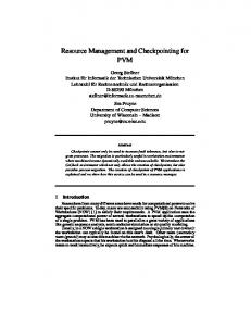
Figure 1: Example service A very simple version of the above example is a group of scientists who have a (virtual) meeting to discuss the output of a simulation, and to compare it with archived results from experiments. Figure 1 illustrates one way in which the network can meet the needs of our scientists. One of the users issues a request to a service provider; the request specifies the location of the scientists, the quality of the video and the approximate computational and I/O requirements of the simulation. This particular service provider does not implement this functionality itself; rather the provider breaks up the request and submits separate requests to service providers specializing in video conferencing and simulation. The service providers satisfy the request and allocate resources, possibly using yet another layer of providers. The original provider coordinates the various players both at startup and at runtime. Runtime actions might involve, for example, reducing video quality if the network load increases dramatically. Alternatively, at particular points of the simulation it may be appropriate to increase the resolution of the simulation output at the expense of the interactive video.
3
2.2 Service Characteristics While we are already experiencing the delivery of services over the Internet today, these services typically have fairly modest networking requirements compared with the examples outlined above. We will use the above service example to illustrate the characteristics of the envisioned services and resulting resource management requirements. At a high level we can characterize the envisioned electronic services market as providing complex, valueadded network services of controllable quality. Complex means that the services will support applications that have multiple end points and use a wide variety of data types with challenging timing and synchronization constraints. Value-added means that the services will integrate low level communication, computation, and storage services, and provide high-level functionalities. Controllable quality means that service providers can ensure service-specific “quality of the service”. For example, a provider could offer high quality video conferencing for board-level meetings, and a lower quality version for informal discussions. This requires resource management mechanisms that give different levels (or type, quality, etc.) of service to different users. Ongoing research efforts on support for integrated services networks [13, 23, 31, 34, 27] partially address this issue, but they only consider basic communication services. Darwin focuses on a much richer set of value-added services. Note that since these value-added services will be the users of the low-level communication services, Darwin might provide some insight in how these low-level mechanisms will be used. The definition of high (or low) quality is service specific, so service providers will need sufficient control over resources to apply them in a way that optimizes the quality of the specific service being provided. This implies a need for resource management mechanisms that are customizable, both at startup time and at runtime. For example, “high-level” QoS requirements (e.g. minimal video frame rate) will typically be met by using specific “low-level” QoS mechanisms (e.g. guaranteed or controlled load service), but the specific low-level QoS mechanisms that are needed to maintain a fixed high-level QoS may change over time depending on load conditions. We are not aware of any existing system that provides systematic support for customization of network resource management over a broad range of time scales. Quality often has a connotation of predictability; i.e. users want to know that if their requests are accepted, they will get the service they expect with an appropriate amount of stability. For example, users will expect their video quality to remain within acceptable boundaries. This requires advanced knowledge of resource needs. Fortunately, we expect that users will often be able to invoke services in a structured way; e.g. as in the above examples, a fairly complete list of participants and of storage access and computational requirements will be known in advance. Using this information about the complete invocation, providers can determine (or approximate) what resources are needed and to what degree they can satisfy the request. Another advantage of having access to a complete, structured request is that it allows providers to do aggressive resource optimization, as we describe below. The alternative to doing resource allocation on a global per-request basis is to allocate resources incrementally, e.g. on a per-flow basis. This is the model supported by RSVP, and it is appropriate for requests where there is a low degree of coordination between endpoints or that have to scale to very large numbers of endpoints. Both models will coexist, since they address different classes of applications, and they may in fact complement each other in certain cases. A final feature of electronic services is that they will be structured in a hierarchical fashion: value-added services are implemented in terms of lower-level services. The motivation for this is reuse of functionality and the need for specialization. We envision an environment where there will be many specialized service providers; other providers build on those services rather than duplicating effort and expertise in those areas. The nature of the service providers will differ at different levels in the service hierarchy. Low-level service providers will focus on managing resources, e.g. communication resources, storage resources (including both archived data and storage for temporary data), and computing resources, which can be general-purpose (e.g. a workstation cluster) or special-purpose (e.g. a real-time MPEG encoder). Higher up in the hierarchy 4
Value Added Service Provider 1
155 Mbps
Value Added Service Provider 2
Bitway Provider 100 Mbps
Value Added Service Provider 1 Value Added Service Provider 2
Bitway Service Provider 1
60 Mbps
40 Mbps
CMU 30 Mbps
Guaranteed Service
U.Pitt
Controlled Best-effort Load Service Service
10 Mbps
SCS
Bitway Service Provider 2
55 Mbps
ECE
seminar seminar video audio
Campus
Distributed Simulation
Control
Audio
FTP
Telnet
WEB
Video
application end point
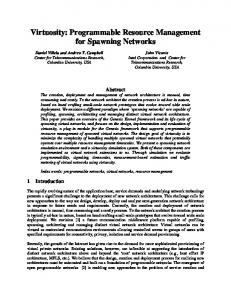
Figure 2: An Example Resource Management Hierarchy we will find increasingly more sophisticated providers that add value through the use of proprietary code and resource management mechanisms. The highest-level services are “integrators” that primarily bundle lower-level services. Hierarchical services require support for hierarchical resource management. While there has been some work in this area, e.g. research on link-sharing [15], we need mechanisms that support a wide range of sharing policies and large, dynamic hierarchies [4, 24]. The virtual network, sometimes also called a virtual mesh or supranet [10], is a core abstraction for resource management in value-added service networks. A virtual network is the set of resources that are allocated and managed in an integrated fashion to meet the needs or service providers or applications. A virtual network does not consist of physical resources, but rather of slices of physical resources that are shared with other providers. A key feature of virtual networks is that providers can manage and control the resources in “their” virtual network in a way that best fits their needs, i.e. customized management. For example, they can specify which of their customers may use virtual network resources and impose sharing policies for those customers, similar to what they could do with physical resources. Combining the notion of a virtual network with that of a service hierarchy results in a hierarchy of virtual networks. Focusing on a specific resource (e.g. a link) reveals a resource tree that captures how that resource is shared. Figure 2 shows the virtual networks of two providers and the resource tree for one of the links they share. The root node represents the physical link resource; the leaf nodes represent the finest granularity of virtual resources, which can be individual flows or flow aggregates (e.g. a best-effort traffic class). Interior nodes represent virtual resources that are managed by entities such as service providers, organizations and applications. The set of arcs connecting a parent to its children specify how parent resources are shared by the children.
2.3 Non-electronic Services The electronic services market we envision has much in common with “real-world,” non-electronic services markets. In both cases, a wide variety of services exists and many options are available for integrating and marketing services. For example, in the regular market, a homeowner who wants to add a room to her house may do it herself after purchasing materials and tools (i,e, use her own resources combined with low-level services), or may instead hire a general contractor (i.e. invoke a high-level service) who performs all the work. We envision that users will have the same options in an electronic services market. Additionally 5
we expect that in both cases the structure of the market will be hierarchical: contractors will often rely on subcontractors to perform some of the tasks. Finally, we expect that in both markets, many services will be offered as an integrated package and most details of the implementation will be hidden from users. For example, when ordering financial data (or bricks), the user will in general not care where they were manufactured or how they were transported. On the other hand, the user may care who was responsible (i.e. what company generated the data (or produced the bricks)), or to what specification the product is guaranteed to conform, since this has an impact on the quality of the final product.
3 Integrated Customizable Resource Management 3.1 Resource Management Requirements There are several requirements for managing a hierarchy of virtual networks to support value-added services. These requirements can be organized into the following classes:
� � �
space: Services need to be able to allocate and manage a rich set of resources (links, switch capacity, storage capacity, compute resources, etc.) in virtual networks to meet their needs. Resources should be allocated in a coordinated fashion, since there are often dependencies between resources, and there should be support for global optimization of resource use. services: Service providers will want to reserve some resources so they can meet certain minimal QoS requirements; at the same time, they will want to dynamically share resources for efficiency. Mechanisms are needed to isolate or dynamically share resources in a controlled fashion across service providers and applications. time: Conditions in the network and user requirements change over time. Services must be able to quickly change how resources are used and allocated, so they can operate under a broad range of conditions.
Because of the broad diversity in services and because service providers will want to differentiate themselves from their competitors, there is a strong need for customization that cuts across these three dimensions: providers will want to customize what resources they allocate, how they share resources with other service providers, and how they adapt their resource use over time.
3.2 Darwin Resource Management Mechanisms While it may seem attractive to have a single resource management mechanism that meets the above requirements, there are several reasons why an integrated set of mechanisms is preferable. First, resource management activities cover a wide range in both time and space: some tasks are invoked rarely (e.g. only at application setup time), whereas others are invoked very often (e.g. on every packet passing through a router); different activities also have different costs. Similarly, some tasks involve only local resources (e.g. those in a single switch), whereas others might involve resources across many networks (e.g. optimizing the position of a videoconference server in a multicountry conference call). Finally, some tasks require detailed network knowledge (e.g. selecting the right QoS parameters for a guaranteed session), while others require domain-specific knowledge (e.g. determining the computational cost of a MPEG to JPEG conversion). Given the diversity of these tasks, software engineering principles argue against building a single monolithic, complex resource management mechanism. Instead, the Darwin architecture comprises a small family of mechanisms:
6
�
�
�
�
High-level resource allocation: This mechanism, sometimes called a resource or service broker, performs global allocation of the resources based on a high-level application request, typically using domain knowledge for optimization. Its tasks include performing tradeoffs between services (for example, trading computation for communication) according to the application-selected value metric (e.g. maximize service quality). It must also perform coordinated allocations for interdependent resources (e.g. since the amount of processor power required by a software transcoder is proportional to the bandwidth of video data flowing through it, these two allocations must be correlated.) We must also be able to interconnect incompatible services or endpoints, for example by automatically allocating and inserting a transcoder service between two otherwise incompatible videoconference participants. The Darwin system contains an example broker called Xena. Runtime resource management: This mechanism injects application or service-specific dynamic behavior into the network. Rather than performing runtime adaptation at flow endpoints (where the information provided by network feedback is potentially stale and inaccurate), it allows rapid local runtime adaptation at the switching points in the network’s interior in response to changes in network behavior. Darwin runtime customization is based on control delegates, Java code segments that execute on routers. Hierarchical scheduling: This mechanism provides isolation and controlled sharing of individual resources among service providers. For each physical resource, sharing and thus contention exist at multiple levels: at the physical resource level among multiple service providers, at the service provider level among lower level service providers, and at the application level among individual flows. The hierarchical scheduler allows various entities (resource owners, service providers, applications) to independently specify different resource sharing policies and ensure that all these policy requirements are satisfied simultaneously. Darwin uses the Hierarchical Fair Service Curve (H-FSC) scheduler. Low-level resource allocation: this mechanism is a signaling protocol that provides an interface between Xena’s abstract view of the network and low-level network resources. It has to allocate real network resources—bandwidth, buffers, cycles, memory—while hiding the details of network heterogeneity from Xena. The Darwin signaling protocol is called Beagle. Multiple Time Scales
Scope of Information and Actions
Coarse
Medium
Fine
Resource Broker
Delegates
Hierarchical Scheduler
Global High-level
Restricted Detailed
Local Network-specific
Signaling Domain-specific
Customization Optimizations
Customized Policies and Actions
Network Parameters
Figure 3: Complementary nature of the Darwin mechanism These mechanisms were chosen because they cover the space, service, and time requirements outlined above. As is illustrated in Figure 3, hierarchical scheduling, delegates, and Xena handle resource management on different time scales (packet forwarding times, roundtrip times, and seconds, respectively). The 7
Service Providers
Xena Appl
2 1
3
Appl
Library Beagle Del.
Library Comm
Appl
Beagle Del.
4
4
Hierarchical Local RM
Beagle Del. Hierarchical Local RM
Classifier Scheduler
Hierarchical Local RM Classifier Scheduler
Appl
Classifier Scheduler
Library
Comm
Library
Appl Comm
Appl
Library
Appl
Comm
Library
Library
Comm
Comm
Comm
Comm
Figure 4: Darwin components difference in time scale impacts the complexity and scope of the decisions that can be made by the mechanisms. Xena can perform sophisticated resource optimization using global information on network status and application requirements. On the other hand, the scheduler can make only simple decisions using local information. The flexibility of customization differs similarly across the three mechanisms. The Beagle signaling protocol coordinates the activities of the mechanisms so they can operate in an integrated fashion. Beagle is also responsible for translating the high-level resource allocation operations into network-specific requests. The four Darwin mechanisms correspond directly to simple operations on a virtual network. Xena identifies the resources that make up a virtual network while Beagle creates the virtual network. The hierarchical scheduler enforces the boundaries between different virtual networks, while delegates manage the resources inside the virtual network they are associated with.
3.3 Darwin System Architecture Figure 4 shows how the components in the Darwin system work together to manage network resources. Applications (1) running on end-points can submit requests for service (2) to a resource broker (Xena). The resource broker identifies the resources needed to satisfy the request, and passes this information (3) to a signaling protocol, Beagle (4), which allocates the resources. For each resource, Beagle interacts with a local resource manager to acquire and set up the resource. The local resource manager modifies local state, such as that of the packet classifier and scheduler shown in the figure, so that the new application will receive the appropriate level of service. The signaling protocol can also set up delegates. Throughout this process, appropriate resource authorizations must be made. Resource brokers have to know what resource pools they are allowed to use, and the signaling protocol and local resource managers must be able to validate the resource allocation request and set up appropriate billing or charging. Figure 5 shows the components on each switch node and their most important interactions. The bottom 8
Xena Other Beagle Entities
Other Routing Entities
Routing
Beagle
Control API
Delegates
Applications Other Delegates
Event Notification
LocalResourceManager
Classifier
Scheduler Routelookup
Figure 5: Darwin node software architecture part of the picture corresponds to the data plane. The focus in this component is on simplicity and high throughput. The top half corresponds to the control plane. Activities in the control plane happen on a coarser time scale; although there is only a limited set of resources available to support control activities, there is more room in the control plane for customization and intelligent decision making. The local resource manager will in general execute on a CPU close to the data path. Routing, signaling and delegates, on the other hand, are not as tightly coupled to the data path, and could run on a separate processor. The Darwin architecture is similar in many ways to traditional resource management structures. For example, the resource management mechanisms for the Internet that have been defined in the IETF in the last few years rely on QoS routing [29, 16] (resource brokers), RSVP [33] (signaling similar to Beagle), and local resource managers that set up packet classifiers and schedulers. The more recent proposals for differentiated service [34] require similar entities. The specific responsibilities of the entities differ, of course, in these proposals. In Darwin, we emphasize the need for customization of resource management, hierarchical resource management (link sharing), and support for resources including not only communication, but also computation and storage.
3.4 Darwin Testbed The Darwin system has been implemented and throughout the paper we show the results of a variety of experiments conducted on a controlled testbed. The topology of the testbed is shown in Figure 6. The three routers are Pentium II 266 MHz PCs running NetBSD 1.2D. The end systems m1 through m8 are Digital Alpha 21064A 300 MHz workstations running Digital Unix 4.0. The end systems p1 and p2 are Pentium Pro 200 Mhz PCs running NetBSD 1.2D and FreeBSD 2.2.5 respectively, and s1 is a Sun Ultrasparc workstation running Solaris 2.5. All links except that between s1 and whiteface are fullduplex point-to-point Ethernet links configurable as either 100 Mbps or 10 Mbps. The link to s1 runs only at 10 Mbps. In the remainder of the paper we describe Xena, delegates, hierarchical scheduling, and Beagle in more detail.
9
m7
p1
m8
Whiteface
s1 m6
m1 Aspen
Timberline
m3
m4
m2
p2 m5
Figure 6: Darwin IP testbed topology
4 Xena: Resource Allocation in Space The process of allocating resources, either by an application or provider, has three components. The first component is resource discovery: locating available resources that can potentially be used to meet application requirements. This requires a resource discovery protocol. The second component is solving an optimization problem: identifying the resources that are needed to meet the application requirements, while maximizing quality and/or minimizing cost. Finally, the resources have to be allocated by contacting the providers that own them. In our architecture, the first two functions are performed by a service broker called Xena, while the third function is performed by the signaling protocol Beagle (Section 7).
4.1 Xena Design The application provides its resource request to Xena in the form of an application input graph, an annotated graph structure that specifies desired services (as nodes in the graph) and the communication flows that connect them (as edges). The annotations can vary in their level of abstraction from concrete specifications (place this node at network address X) to more abstract directives (this node requires a service of class S). These annotations are directly related to the degree of control the application wishes to exert over the allocation: a mesh with fewer (or more abstract) constraints presents more opportunities for optimization than a highly specified one. In the most constrained specification, the application specifies the network addresses where the services should be placed, the services themselves, and the QoS parameters for the flows that connect them. In this style of specification, Xena’s optimization opportunities are limited to coarse routing: selecting communication service providers for the flows in the mesh. In a less constrained specification, the application can leave the network address of a service unspecified. This provides an additional degree of freedom: Xena now has the ability to place nodes and route flows. In addition, the application can leave the exact QoS parameters unspecified, but instead indicate the flow’s semantic content. An example of a flow specification might be Motion JPEG, with specific frame rate and quality parameters. In addition to providing sufficient information to maintain meaningful application semantics, this approach gives Xena the opportunity to optimize cost or quality by inserting semantics-preserving transformations to the mesh. For example, when a Motion JPEG flow needs to cross a congested network segment, Xena can insert matched pair of transcoders at two ends of the network segment. The first transcoder converts the flow to a more bandwidth efficient coding format (such as MPEG or H.261), and then convert it back to JPEG on the far side. Another 10
optimization is the lowest-cost type unification: a group of nodes receiving the same multicast flow (say, a video stream) need to agree with the sender on the encoding that is used. If there is no single encoding acceptable to all parties, Xena can insert “type converter” nodes appropriately. A feasible solution to the resource selection problem is one that satisfies all the constraints based on service-specific knowledge or application specification, e.g. entities at flow endpoints must agree with the type of data that will be exchanged. Given a set of feasible solutions, Xena evaluates each according to the optimization criteria. In Xena, these optimization criteria are encoded by an application-specified objective function that maps candidate solutions to a numeric value: this function is composed of a sum of terms, where each term represents the “quality” of a particular layout choice. This allows applications to define service quality in an application-specific way. For tractability’s sake the objective functions currently must be selected from a small set of built-in functions that represent useful objectives; e.g. minimize price, maximize throughput, minimize network delay. By using application specific criteria to guide resource selection, Xena in effect allows applications to customize the definition of service quality.
4.2 Implementation Our current implementation of Xena includes the interfaces to the other system entities (applications, service providers, and Beagle), plus the solving engine and optimizations described above. The application interface allows the specification of request that include nodes, flows, types, and transcoders. The current Xena implementation does not have a general resource discovery protocol. Instead, it offers a mechanism through which services can register their availability and capabilities. This information allows Xena to build a coarse database of available communication and computation resources, and an estimate of their current utilization. Additionally, Xena maintains a database that maps service and flow types (e.g. transcoding or transmitting MPEG of a certain quality) to their effective resource requirements (e.g. CPU cycles or Mbps). Finally, there is a database that contains the various semantics-preserving transformations (e.g. JPEG-to-MPEG) and how to instantiate them. Xena currently expresses the optimization problem as a 0-1 integer program, and turns it over to a solver package [5] that generates a sequence of successively better solutions at successively greater computation cost. More specifically, the following variables encode the decisions Xena has to make:
PService;Address FFlow?id;Content?type CService;Configuration
Service placement Flow type Service configuration
1 if Service is placed at Address; 0 otherwise 1 if Flow-id is of type Content-type; 0 otherwise 1 if Service is configured according to Configuration; 0 otherwise where the configuration of a service that receives and/or transmits k flows is the k-tuple of the content types of those flows, i.e. Configuration = (Content ? typei )k . Various requirements for semantically correct service delivery are expressed as constraints in the linear program. For example, the constraint
8i
:
XP j
Servicei ;Addressj
=
1
specifies that a service should be placed on precisely one node. As another example, the following constraint specifies that the flow types of flows that enter or leave a service should match the configuration of the service:
8 i; j; k; l : PService ;Address j CService ;Configuration ! FFlow Address ;l ;FlowType Service ;Configuration ;l where the functions Flow(a; l) and FlowType(s; c; l) extract the lth flow and flow type from the node and i
j
i
k
service configuration respectively. 11
(
j
)
(
i
k
)
Finally, the optimization function can either minimize cost or optimize quality:
minimize or maximize
X v � cost(v) Xv v � quality(v) v
By appropriately selecting the cost or quality weigths, brokers can implement a service-specific definition of quality of service. For example, the weights can be chosen to allocate the minimal amount of bandwidth for a flow that is necessary in that application domain or for that service provider’s quality standards. Similarly, the weights can be tuned for each individual request to reflect application preferences. Since the optimization problem is generally NP-hard, this approach is only appropriate for small to medium size problems. Work is in progress on defining heuristics and other simplifying assumptions that will make the problem tractable. This approach will necessarily trade quality for performance; i.e. our goal is to find high quality (but not, in general, optimal) solutions at a reasonable cost.
4.3 Example Consider an application in which four scientists communicate via a videoconferencing tool that uses software MPEG/JPEG coders and collaborate on a distributed simulation that runs over our distributed computing testbed. Figure 7(a) shows the abstract resource mesh supplied to Xena. For the sake of clarity, some detail has been omitted; for example, we have depicted communication flowing in one direction only. For the video conferencing tool, since the scientists are physically located at their machines, the application provides to Xena specific network addresses (m1, m2, m5, m6) for the nodes participating in the videoconference. The nodes are also annotated by the requested service types (Video Source, Video Display). Note that the video source at m2 is capable of emitting only MPEG. The nodes are connected by a multipoint-to-multipoint flow (only partially depicted). This flow specification describes only the connectivity between the nodes; the flow’s exact QoS parameters are left unspecified. For the distributed simulation, the application does not specify what nodes should participate. The mesh generated by Xena is shown at the top of Figure 7(b); the rest of the figure illustrates the operation of Beagle and is explained in more detail in Section 7. The scientists request the minimize cost optimization strategy and at the time of the request, computation is costly relative to communication because of existing loads. This means that, even though it is simplest to use MPEG for the video, the less computation-intensive all-JPEG solution is more desirable. Xena can compensate for m2’s inability to emit JPEG by employing the MPEG-JPEG converter registered at m4; despite the detour through m4 and its computation cost, this solution comes in at an overall lower cost than the all-MPEG approach. Moreover, due to severe loads on m7, m8, and the router whiteface, which are expressed as a high cost, the least costly solution collocates the distributed simulation nodes with the videoconference nodes, at m1, m2, m5, m6. Once node placement and route selection has occurred, Xena invokes Beagle to perform the resource allocation.
5 Customizable Runtime Resource Management We discuss how delegates perform customized runtime resource management, describe the delegate runtime environment implemented in Darwin, and illustrate delegate operation using an example.
12
Video Source [MPEG or JPEG]
m1
m6
Video Display [MPEG or JPEG]
Video Source m2 [MPEG only]
m5
Video Display [MPEG or JPEG]
(a) ����������� ����� �����
����
Simulation [app-specific type]
?
?
Simulation [app-specific type]
Simulation [app-specific type]
?
?
Simulation [app-specific type]
������
m7
m8
Whiteface
S1 (JPEG) F1
m1
������� ����������� �� �
Timberline
L1
F2
�������� �������
QoS Type Guaranteed
F2
Guaranteed
F3 F4
WFS WFS
F lo w G ro u p F 3 an d F 4
������
����� � ����� �������
R2 (JPEG)
Transcoder FlowSpec (p, r, b) = (100, 2, 8) (R, S) = (10, 150) (p, r, b) = (100, 5, 8) (R, S) = (15, 50) W = 50 W = 10
A g g reg ate Q o S T yp e C ontrolled Load
A g g reg ate F lo w S p ec (p, r, b) = (100, 4, 128)
Application G Video
Video 10 F1
G 15
Simulation WFS
G
F2
F1
F3
F4
������������ �������� 29
29 25
(c)
m4
S2 (MPEG)
Flow F1
m6
m5 m3
(b)
R1 (JPEG) F3 F4
Aspen m2
����������
�� ���
L2
Application G 4 Simulation F3
25 Video 10 F1
F2
��!���"������ � #
G 15 F2
Application G 4 Simulation WFS 50 10 F3
F4
��!� ��� � ���"������
Figure 7: Handling an application service request in Darwin 13
5.1 Delegates We use the term “delegate” for code that is sent by applications or service providers to network nodes in order to implement customized management of their data flows. Delegates execute on designated routers, and can monitor network status and adjust resource management on those routers through a control interface, as shown in Figure 5. Delegates can be viewed as an application of active networks [25]: network users can add functionality to the network. It is, however, a very focused application: delegate operations are restricted to traffic management. A critical design decision for delegates is the definition of the control interface, i.e. the API that delegates use to interact with the environment. Several design goal constrain the definition of the API. First, it is highly desirable that the API be usable across multiple platforms, without being tightly tied to a specific model of resources. In the long run, standardized interfaces for use by signaling protocols will also be useful for delegates. Second, the API should balance the flexibility of delegate actions with the increase in complexity and cost in routers associated with supporting delegates. If the API is too restricted, delegates may be rendered virtually useless, while to broad an API may make it difficult to efficiently and safely support delegates. Finally, the API must support efficient interactions between delegates and the router core under a broad set of conditions. For example, delegates can detect congestion events either by polling router state, or by arranging to be notified of events detected by the router core. The former solution can impose an unreasonable polling load, especially in the presence of large numbers of delegates, while the latter solution can slow down the router core, especially if many kinds of events can be specified. The challenge is to identify a small number of event types that will cover most needs, and hence eliminate most polling. We have identified the following classes of operations that should be available to delegates:
� �
� �
Delegates can monitor network status. This can involve probing of network state, e.g. queue occupancy, error flags, etc. It can also involve posting requests for notification of a small set of specific events, such as crossing of a queue occupancy threshold and occurrence of a failure condition. Delegates can change the resources allocated to flows. First, they can change flows’ quality of service by adjusting resource allocation and sharing rules. In addition, they can split or merge flows by adjusting packet classification. Splitting allows different groups of packets in a flow to be treated differently. For example, a delegate can implement selective packet dropping by splitting off a subflow and marking it for discard. A delegate can also elect to receive special control packets by splitting off a subflow and marking it for delivery to itself. Delegates can affect routing. For example, a delegate might choose to reroute a flow inside the virtual network for load balancing reasons, or to direct a flow to a compute server that will perform data manipulations such as compression or encryption. Delegates can send and receive messages. This might involve coordinating activities with peers on other routers, or providing network feedback to application processes on endpoints.
Another key issue in the design of a delegate facility is the interaction of actions taken by delegates with those of signaling and network management, resource management entities that operate on longer time scales. The most fundamental requirement is that these potentially concurrent activities maintain a consistent network state. A second, performance-driven requirement is that they interact efficiently, without complex locking protocols. Hierarchical resource management of the kind used in Darwin provides a good solution for both requirements. Delegates are associated with nodes in the resource tree and a delegate will typically be authorized to apply the operations listed above to the flows in "its" subtree. Using the resource tree in Figure 2 as an example, a delegate associated with the SCS node could increase the share of bandwidth available for Distributed Simulation. This organization provides a certain locality in the organization space, 14
which simplifies the interaction between the multiple signaling entities (delegates and Beagle). Once the signaling protocol has set up a new flow (node) with an initial subtree, and its associated delegates, the delegate can operate in relative isolation, until the global flow is changed, at which point the delegate is notified to adjust its suballocations. The use of delegates also raises significant safety and security concerns. Delegates are in general untrusted, so the router has to ensure that they cannot corrupt state in the router or cause other problems. This can be achieved through a variety of run time mechanisms (e.g. building “sandbox” that restricts what the delegate can access) and compile time mechanisms (e.g. proof-carrying code [22]). A related issue is that of security. At setup time, the router has to make sure that the delegate is being provided by a legitimate user, and at runtime, the local resource manager has to make sure that the delegate only acts on flows that it is allowed to manage. The authentication and authorization of delegates will be performed jointly by the signaling protocol and the local resource manager; authentication and authorization are not yet implemented in our current system.
5.2 Implementation Our current framework for delegates is based on Java and uses the Kaffe Java virtual machine [30], which is capable of just-in-time (JIT) compilation and available for many platforms. This environment gives us acceptable performance, portability, and safety features inherited from the language. Delegates are executed as Java threads inside the virtual machine “sandbox.” Currently, delegates can run with different static priority levels, although a more controlled environment with real-time execution guarantees is desirable. The API that gives users access to resource management functions and event notification is implemented as a set of native methods that call the local resource manager, which runs in the kernel. Table 1 presents the methods of the Java class delegate.Clschd, which implements the API to the packet classifier and scheduler. Communication among delegates and between delegates and endpoints uses IP sockets, built on top of standard java.net classes. Rerouting functions have not yet been implemented. While this environment is sufficient for experimentation, it is not complete. It needs support for authentication, and mechanisms to monitor and limit the amount of resources used by delegates. The interaction of delegates with the router core is also very specific to the H-FSC scheduler code used in Darwin. Clschd methods add del set dsc on dsc off probe reqMonitor retrieve
description Adds a node in the packet scheduler hierarchy Deletes a node from the packet scheduler hierarchy Changes parameters on the scheduler queue Activates selective discard on a class in the packet classifier Deactivates selective discard on a class in the packet classifier Reads scheduler queue state Requests asynchronous congestion notification Retrieves packet scheduler hierarchy
Table 1: Methods available at the Delegate/Local Resource Manager API
5.3 Experiment We present an example of how delegates can be used to do customized runtime resource management.
15
25 21 19
Frame Rate (fps)
20
18. 4
15
15
10
8.4
7.5
5 0.4 0.5 0 Shared
Reservation
Sel. Drop
A. Sel. Drop
Figure 8: Video quality under four scenarios Suppose a network carries two types of flows, data and MPEG video, similar to the example in Figure 7. If packets are dropped randomly during congestion, the quality of the video degrades very quickly. The reason is that MPEG streams have three types of frames of different importance: I frames (intracoded) are self contained, P frames (predictive) uses a previous I or P frame for motion compensation and thus depend on this previous frame, and B frames (bidirectional-predictive) use (and thus depend on) previous and subsequent I or P frames. Because of these inter-frame dependencies, losing I frames is extremely damaging, while B frames are the least critical. We direct three flows over the Aspen-Timberline link of the testbed: 2 MPEG video streams and an unconstrained UDP stream. Both video sources send at a rate of 30 frames/second, and our performance metric is the rate of correctly received, useful frames. Figure 8 compares the performance of four scenarios. In the first scenario, the video and data packets are treated the same, and the random packet losses result in a very low frame rate. In the second case, the video streams share a bandwidth reservation equal to the sum of the average video bandwidths. This improves performance, but the video streams are bursty and the random packet loss during peak transfers mean that less than a third of the received frames are useful. In the third scenario, we add a control delegate on Aspen. The delegate monitors the length of the queue used by the video streams, and if the queue grows beyond a threshold, it instructs the packet classifier to identify and drop B frames, which are marked at the source with an application-specific identifier. Packet dropping stops when the queue size drops below a second threshold. Figure 8 shows that is quite effective: the frame rate roughly doubles. The reason is that by eliminating B frames from the queue, the I and P frames are protected from packet dropping. While delegates provide an elegant way of selectively dropping B frames, the same effect could be achieved by associating different drop priorities with different frame types, e.g. layered video coding. In scenario four we use a delegate to implement a more sophisticated customized drop policy. In scenario three, typically too many B frames are dropped, because all flows are affected simultaneously. A better approach is to drop only the B frames of a subset of the video streams, assuming that is sufficient to relieve congestion. The advantage of having a delegate control selective packet dropping is that it can implement customized policies for controlling what video streams are degraded. Scenario four in Figure 8 shows the results for a simple “time sharing” policy, where, during congestion, every few seconds the delegate
16
switches the stream that has B frames dropped. This improves performance by another 10-20%. Policies that differentiate between flows could be implemented similarly.
6 Hierarchical Scheduling As discussed in Section 2, from a resource management point of view, a service-oriented network can be viewed as a hierarchy of virtual networks and each virtual network represents the set of resources that are managed by an entity such as a service provider or an application. For each individual physical resource, sharing and thus contention exist at multiple levels: at the physical resource level among multiple service providers, at the service provider level among lower level service providers or organizations, and at the application level among individual flows. These relationships can be represented by a resource tree: each node represents one entity (resource owner, service provider, application), the slice of the virtual resource allocated to it, the traffic aggregate supported by it, and the policy of managing the virtual resource; each arc represents the virtual resource owner/user relationships. An example of a resource tree is shown in Figure 2. The ability to customize resource management policies at all sharing levels for a resource is one of the key requirements and distinctive features for service-oriented networks. The challenge is to design scheduling algorithms that can simultaneously satisfy diverse policies set by different entities in the resource management tree. In Darwin we use the Hierarchical Fair Service Curve (H-FSC) scheduling algorithm [24].
6.1 H-FSC Algorithm and Customization Features In the H-FSC scheduler, associated with each link is a class hierarchy that specifies the resource management policy. Each interior class represents some aggregate of traffic flows that are managed by an entity such as the link owner, a service provider, and so on. The resource management policy for each entity is then mapped to one that can be implemented by the Fair Service Curve (FSC) algorithm. The goal of the H-FSC algorithm is to simultaneously satisfy all the FSC policies of all entities in the hierarchy. In FSC, a stream i is said to be guaranteed a service curve Si (�), if for any time t2 , there exists a time t1 < t2 , which is the beginning one of stream i’s backlogged periods (not necessarily including t2 ), such that the following holds
Si (t2 ? t1 ) � wi (t1 ; t2); (1) where wi (t1; t2 ) is the amount of service received by session i during the time interval (t1 ; t2]. Consider an entity that manages N streams, where each stream can be an application flow, or a flow aggregate. The amount of resource the entity manages is the service guaranteed by its parent entity, denoted by S (t). Without going into the details of the FSC algorithm, we state that the FSC algorithm can (1) guarantee the service curves for all streams if the stability condition N i=1 Si (t) � S (t) holds; (2) fairly allocate the excess service if some flows cannot use their guaranteed service. We decided to use the H-FSC scheduler in Darwin because of the following two important properties of H-FSC. First, as long as the stability condition holds, i.e., the sum of the service curves of child entities is no greater than the service curve of the parent entity, H-FSC allows FSC policies to be combined arbitrarily in a hierarchy while satisfying all of their requirements simultaneously. Second, the FSC algorithm, which is used at each level in a H-FSC scheduler, provides a general framework for implementing many policies. For example, by ensuring a minimum asymptotic slope of Si (t) independent of the number of competing streams, a guaranteed bandwidth service is provided to stream i. By assigning Si (t) to be S (t) � �i = N j =1 �j for all streams, a weighted fair service in which stream i has a weight of �i is implemented. Unlike various fair queueing algorithms, FSC decouples delay and bandwidth allocation.
P
P
17
The H-FSC feature that entities sharing the resource at different levels can manage “their” share of the resources independently is critical for service providers. For example, in the resource hierarchy shown in Figure 2 the two service provider use radically different resource management policies: Service Provider 2 supports the IETF Intserv QoS model (guaranteed and controlled load) for individual traffic streams, while the more sophisticated Service Provider 1 supports organization-based QoS, where the organizations and applications can specify the dynamic sharing relationship for their traffic streams. Moreover, once the resource sharing relationship between Provider 1 and Provider 2 is set up (weighted sharing with 100 Mbps and 55 Mbps for each), the two providers can independently change resource use without affecting the QoS properties of traffic supported by the other provider. For example, Provider 1 can admit new flows or change the resource allocation for existing flows, without having to coordinate with Provider 2, as long as its stability conditions is met.
6.2 Implementation The implementation of the H-FSC scheduler in Darwin requires two extra components: a packet classifier, and an API for signaling protocols. Before they can be scheduled, incoming data packets must be classified and mapped to packet queues. To support traffic flows of various granularities, we have devised a highly flexible classification scheme. Each flow is described by a 9 parameter flow descriptor: source IP address, CIDR-style source address mask, destination IP address, CIDR-style destination address mask, protocol number, source port number, destination port number, application specific ID (carried as an option in the IP header), and CIDR-style application specific ID mask. A zero denotes a “don’t care” parameter. Using this scheme, flows such as end-to-end TCP connections, aggregates of traffic between networks, and WWW, FTP, TELNET services can be specified. With the application specific ID, we can even sub-divide an end-to-end traffic flow into application specific sub-flows, such as the different frame types in a MPEG flow. The control API exported by the scheduler is as discussed in Section 5. The processing overhead associated with classification and queueing in our implementation is suitably low for use in our Darwin testbed. Classification overhead is 3 �s per packet with caching on a 200 MHz Pentium Pro system. Average queueing overhead is around 9 �s when there are 1000 flows in the system. This low overhead allows us to easily support link speed of 100 Mbps in our prototype network testbed.
6.3 Experiments We present the results of a set of experiments that demonstrate the importance of being able to reserve resources and to control dynamic bandwidth sharing. In the first set of experiments, we run two distributed computations, Fast Fourier Transform (FFT), simultaneously to show the effect of reserving resources. Hosts m1, m4, and m7 participate in the first mesh (FFT-1) on 0.5 KB of data for 96 iterations. Hosts m2, m5 and m8 participate in the second FFT mesh (FFT-2) on 1 KB of data for 32 iterations (please refer to Figure 6 for the testbed topology). All network connections in this set of experiments are configured at 100 Mbps. The all-to-all communication in the FFT often dominates the execution time. FFT uses TCP for communication and the communication pattern is highly bursty: the burst data rate is approximately 80 Mbps. Figure 9 summarizes the results. Scenario 1 shows the base case: in an idle network and without reservations, the communication times are 27.66 s and 51.05 s for FFT-1 and FFT-2 respectively. In Scenario 2, we introduce two 90 Mbps UDP traffic streams from m3 to p1 and from m6 to p1, causing congestion on the inter-router links. Since the FFTs use TCP for communication, their performance degrades significantly because the competing traffic does not use congestion control. To improve the FFTs’ performance, protection boundaries must be drawn between the background traffic and the FFTs. In 18
0.5 KB
1 KB
400
Communication time (s)
365.01
350 311.22
300 250
236.41 231.93 205.73
200
165.78
150 100 50
51.05 27.66
0 1
2
3
4
Scenario
Figure 9: Communication times of FFT meshes experiments on different data sizes under various scenarios. (1) base case: no other traffic and reservation in the network. (2) two 90 Mbps background UDP streams, no reservations. (3) same as (2), but with 20 Mbps per-flow reservations for FFT. (4) same as (2), but with 40 Mbps application aggregate reservation for FFT. Link
20 Mbps
FFT-1
20 Mbps
FFT-2
Link
60 Mbps
40 Mbps
60 Mbps
UDP
FFT-1 FFT-2
UDP
(a)
(b)
Figure 10: Resource sharing hierarchies on congested links in FFTs experiments. (a) Per-flow reservation. (b) Aggregate reservation. Scenario 3, we use reservations to guarantee that each FFT mesh gets at least 20 Mbs of bandwdith on each inter-router; Figure 10(a) shows the corresponding resource tree. The remaining bandwidth is given to the background traffic. Under this per-flow reservation scheme, the communication times of the FFTs improved by 24% and 36%. In Scenario 4, we apply a shared reservation of 40 Mbps for both FFTs; Figure 10(b) shows the resource tree. Since the FFT traffic is very bursty, the advantage of dynamically sharing the reserved bandwidth is significant: the communication time is reduced by another 13% and 29%. We conclude that it is important to be able to reserve resources, not only for flows, but also for flow aggregates. In our second set of experiments, we demonstrate how hierarchical scheduling can be used to control dynamic bandwidth sharing. Consider an distributed interactive simulation application that combines an FFT with an interactive componenent such as a video stream or shared white-board. In this experiment, the FFT (1 KB of data and 32 iterations) uses m2, m5, and m8, while the interactive adaptive component is modeled by a TCP connection from p2 to s1. In addition, background traffic is modeled by a full-blast UDP traffic stream from m6 to p1. With “vanilla” resource distribution, we reserve 40 Mbps for the FFT mesh, 1 Mbps for the TCP stream, and the remaining bandwidth is given to the background UDP stream (Figure 11(a)). With this reservation scheme, the TCP stream achieves a throughput of 1.4 Mbps, while the
19
Link
40 Mbps
Link
59 Mbps
41 Mbps
59 Mbps
UDP
Appl
UDP
1 Mbps FFT
TCP
40 Mbps
FFT
1 Mbps
TCP
(a)
(b)
Figure 11: Resource sharing hierarchies on congested links in distributed interactive simulation experiments. (a) Per-flow reservation. (b) Hierarchical reservation.
FFT communication time TCP throughput
Non-hierarchical scheduling 70.8 sec 1.4 Mbps
Hierarchical scheduling 73.2 sec 5.3 Mbps
Table 2: Non-hierarchical vs hierarchical scheduling. Note the 276% improvement in TCP throughput when hierarchical scheduling is used. FFT communication time is 70.8 seconds (Table 2). With hierarchical resource management we group flows as is shown in Figure 11(b). While the overall reservation for the application remains the same, the hierarchy specifies that TCP (FFT) gets the first chance at using any bandwidth left unused by FFT (TCP). The result is that the throughput of the TCP stream is now 5.3 Mbps, almost a factor of four improvement, while the communication time of the FFT increases by an insignificant amount of 3% to 73.2 seconds (Table 2). This example demonstrates that hierarchical scheduling makes it possible for applications to cooperatively share the reserved resources more effectively within the application boundary and that specifying specific resource trees, applications and service providers can customize how resources are shared.
7 Beagle: Signaling The Beagle signaling protocol provides support for the customizable resource allocation model of Darwin. Unlike more traditional signaling protocols such as RSVP [33] and PNNI [3] which operate on individual flows, Beagle operates on virtual networks or meshes. We elaborate on some key Beagle features in this section.
7.1 Beagle Design On the input side, Beagle interfaces with Xena to obtain the virtual network specification generated by Xena. The virtual network is described as a list of flows and delegates, plus resource sharing specifications
20
that describe how flows within a mesh share resources amongst them. The example virtual network in Figure 7(b) shows two video flows and two distributed interactive simulation flows. Each flow is specified by a flow descriptor as described in Section 6.2 and information such as a tspec and a flowspec object, as in the IETF IntServ working group model. A delegate is characterized by its resource requirements (on CPU, memory, and storage), its runtime environment, and a list of flows that the delegate needs to manipulate. The delegate runtime environment is characterized by a code type (e.g. Java, Active-X) and runtime type (e.g. JDK 1.0.2, WinSock 2.1, etc.). The virtual network typically also includes a number of designated routers which identify the mesh core. In the example, Aspen and Timberline are the designated routers. After receiving a request, Beagle issues a sequence of flow setup messages to the different nodes in the mesh, each message specifying what total resources are needed on a link, plus a grouping tree that specifies how these resources should be applied. An efficient setup of a mesh includes the establishment of the core, and individual flow setups initiated by the senders or receivers that rendezvous with the core in designated routers. Our initial implementation uses simple per-flow setups and a hard state approach based on three-way handshakes between adjacent routers. Future work includes optimizing mesh setup and evaluating the use of soft state for some or all of the mesh state. On each node, Beagle passes a resource trees (Figure 7(c)) to the Local Resource Manager to allocate resources for flows. This interface is similar to the one described in Section 5 (Table 1). Beagle also establishes delegates onto switch nodes (for resource management delegates), or compute and storage nodes (for data processing delegates). For each delegate request, Beagle locates the appropriate runtime environment, initializes the local resource manager handles and flow reservation state, and instantiates the delegate. The handles allow the delegate to give resource management instructions to the local resource manager for the flows associated with it. In the future, Beagle will also provide support for communication channels between control delegates belonging to the same service and also provide mechanisms to recover from control delegate failures.
7.2 Customization Support 7.2.1
Resource Distribution
In the previous section we described how dynamic resource sharing can be controlled and customized by specifying an appropriate resource tree for each resource. This could be achieved by having applications or Xena specify the resource trees to Beagle, so that it can install them on each node. There are two problems with this approach. First, how one specifies a resource tree is network specific and it is unrealistic to expect applications and brokers to deal with this heterogeneity. Second, applications and brokers do not specify each physical link; instead they use virtual links that may represent entire subnets. Beagle uses the hierarchical grouping tree abstraction to deal with both problems: it is an abstract representation of the sharing hierarchy that can be mapped onto each link by Beagle. Figure 7(b) gives an example. The hierarchical grouping tree encodes the hierarchical sharing structure of all flows sharing a virtual link. Once it knows the actual flows that share a particular physical link in the network, Beagle prunes the hierarchical grouping tree, eliminating flows that do not exist at that link. To deal with network heterogeneity, interior nodes in the hierarchical grouping tree have generic QoS service types associated with them instead of network-specific sharing specifications. The leaf nodes of the grouping tree represent flows whose QoS requirements are expressed by individual flowspecs. Service-specific rules describe how child node flowspecs are aggregated into parent node flowspecs in deriving a physical link resource tree from the grouping tree. This involves pruning the grouping tree to eliminate flows that do not exist at a particular link and converting flowspecs at each node into appropriate low-level scheduler-specific parameters, such as a weight for hierarchical weighted fair share schedulers [4] or a service curve for the Hierarchical Fair Service Curve scheduler [24].
21
7.2.2
Temporal Sharing
There are often resource sharing opportunities on time scales larger than what can be expressed in tspecs and flowspecs. For example, a conferencing application may ensure that at most two video streams are active at any time, or an application may like to associate an aggregate bandwidth requirement for a group of best-effort flows. Applications and resource brokers can specify this application-specific information by handing Beagle temporal sharing objects that list sets of flow combinations and their associated aggregate flowspecs. Beagle can then use this information to reduce resource requirements for a group of flows sharing a link. The temporal sharing object is similar in spirit to the resource sharing approach used in the Tenet-2 scheme [17]. However, control of flow routing using designated routers allows us to take better advantage of sharing opportunities. The temporal sharing object also generalizes RSVP’s notion of resource reservation styles. However, RSVP limits aggregation to flows within a multicast session and the aggregate flowspecs must be the result of either a sum or a least upper bound (LUB) operation on the individual flowspecs. In Beagle, the temporal sharing object can be used to group arbitrary flows within an application mesh and any aggregate flowspec can be used. As an example, in Figure 7(b), the distributed interactive simulation application associates an aggregate Controlled Load service flowspec with the two simulation flows. The hierarchical grouping tree and the temporal sharing objects both define ways in which an application can tailor resource allocation within the mesh. However, they are separate concepts and are orthogonal to each other. If both types of sharing are specified, the resource tree is derived by applying the temporal sharing specification at every level of the tree. If the temporal sharing object lists flow groups that do not fall under the same parent node in the resource tree, the temporal sharing behavior is ignored. The example in Figure 7(b) shows the use of both sharing objects. The resulting link resource sub-trees at links L1 and L2 , assuming the use of hierarchical weighted fair share schedulers [4], are shown in Figure 7(c).
! $��� ) % $ #������� � " " & ' ( �� ������ ���) � � � �
� � �
� � �
� � � �
� �
) � � �� ���� �� ������ ����������
7.3 Implementation
Figure 12: Beagle prototype and Beagle API implementation.
A prototype of the Beagle resource allocation protocol has been implemented on the Darwin testbed. Figure 12 shows the implementation of the Beagle prototype system on a router and host, both of which 22
are UNIX workstations. This implementation is based on the RSVP implementation distributed by ISI (available from (ftp://ftp.isi.edu/rsvp/release). Applications and/or Xena can invoke Beagle by making appropriate API function calls. The API (shown by the shaded portions in Figure 12) is a library that is compiled in as part of the application. It communicates with the Beagle daemon through UNIX domain sockets. Important API calls include creation of a mesh, flow or delegate and registering a delegate runtime and listening for incoming delegates. The API also has calls to attach to an existing mesh and to dynamically modify flow characteristics during runtime. The API also has a callback mechanism that is used to asynchronously notify applications about various events such as setup success/failure, incoming requests, etc. The Beagle daemon communicates with other Beagle daemons using raw IP. The current implementation does not have suppport for temporal sharing.
7.4 Experimental Evaluation To evaluate the performance of the Beagle prototype implementation,we measured end-to-end setup latencies for flows and delegates, and per-router flow setup processing times on the Darwin testbed. The experiment involved setting up the virtual network shown in Figure 7(b). All measurements reported are averages from 100 runs. The average end-to-end latency through two routers was 7.5ms for flow setup and 3.8ms for delegate setup. The flow setup processing time on each router was 2.4ms, about 68% of which was spent in interacting with the local resource manager. This involves admission control and setting up flow state in the packet classifier and scheduler. The current Beagle prototype supports about 425 flow setups per second. This is comparable to connection setup times reported for various ATM switches. However, we expect improvement in these results by optimizing the implementation.
8 Darwin System Demonstration In this section we detail an experiment that illustrates the integrated operation of the various Darwin system components. We use a variant of the example application of Figure 7 for this experiment. Here, the four scientists are connected using two point-to-point video streams, and the distributed simulation consists of a three-node distributed FFT. The machines involved in the video conference in this case are m1, m2, m5, and m6. Source m2 can send either 8-bit uncompressed video or Motion JPEG (MJPEG) compressed video; source m6 can send only uncompressed video. The three nodes used for the simulation are floating (not bound to a fixed address) as in Figure 7. The network used for this integrated experiment is the same as our testbed (Figure 6), except that the link between aspen and whiteface has been deliberately disabled in order to increase congestion on the other links. In the following sections we use a combination of performance results and screen shots of the running system to demonstrate the operation of various Darwin components.
8.1 Xena We consider two scenarios under which Xena has to generate a virtual network layout for the given application input. In the first “abundant bandwidth” scenario, bandwidth is plentiful on all the links, but computational cycles are relatively scarce. In the second “scarce bandwidth” scenario, the links are heavily loaded, but computational resources are relatively abundant. Xena accounts for these loads by adjusting the costs of various resources. Costs are assigned according to the quantity of the resource desired and its availability. For example, the cost for raw video flows is higher than for MJPEG flows because raw video requires more bandwidth; also, the cost for a given quantity of some resource may be higher than otherwise if the level of contention is high for that resource. Xena achieves this latter effect, somewhat crudely, by assigning an overlap penalty when more than one service is assigned to the same endpoint.
23
Figure 13: Xena virtual network layout in the abundant bandwidth scenario.
Figure 14: Xena virtual network layout in the scarce bandwidth scenario. Figures 13 and 14 are screen shots of the running Xena prototype showing virtual network layouts generated by Xena. In the abundant bandwidth scenario, Xena selects the uncompressed video encoding which requires more bandwidth, but is computationally less expensive. It places the simulation tasks on nodes m4, m7, and m8, avoiding the video endpoints (m1, m2, m5, and m6). It also places two simulation nodes (m4 and m7) on endpoints attached to the same router, thus minimizing the use of link bandwidth. In contrast, in the scarce bandwidth scenario, Xena selects the less bandwidth-intensive MJPEG video encoding to reduce the use of expensive communication resources. To accomodate m2, which supports only uncompressed video, it inserts a video transcoder into the mesh. The transcoder is placed close to the video source to minimize the use of expensive link bandwidth. The transcoder is a hardware MJPEG compressor that provides the ability to dynamically control compression quality; note that video streams of higher quality require more bandwidth. In order to opportunistically use available bandwidth, Xena also instantiates a control delegate on timberline which is responsible for monitoring the available bandwidth and setting the compressor’s quality knob appropriately. Xena distributes the simulation tasks on the remaining 24
Figure 15: Resource tree for the timberline !whiteface link. nodes (m3, m7, and m8) thus avoiding the overlap penalty for computations.
8.2 Beagle Figure 14 shows the virtual network specification that Xena provides to Beagle for the scarce bandwidth scenario; the specification for the other scenario is similar but slightly simpler. The specification includes the topology of the virtual network, the location of the transcoder, the resource sharing tree, and the control delegate that dynamically controls the operation of the transcoder. The resource sharing tree is translated into a network-specific resource tree for each of the links in the mesh; Figure 15 is a screen shot generated using the H-FSC scheduler user interface program that shows the resource sharing tree setup by Beagle for the timberline!whiteface link. The numbers labeling the nodes of the tree are internal node identifiers used by the H-FSC scheduler. Beagle also sets up and initializes both the transcoder and the control delegate.
8.3 Execution In this section we present experimental results by executing the video and FFT applications under both of the scenarios discussed earlier. We conduct three experiments—one in the abundant bandwidth scenario, and two in the scarce bandwidth scenario—and present bandwidth utilization plots and estimates of received video quality in each case. The two experiments in the scarce bandwidth scenario are designed to demonstrate the advantage of using a control delegate to dynamically tune the operation of the transcoder. In all experiments, 70% of the link bandwidth is allocated to the application and the remaining is used by a UDP cross-traffic flow. In the abundant bandwidth scenario, all links are configured to run at 100 Mbps. Both uncompressed video flows are allocated a bandwidth of 18 Mbps each (320x240 eight-bit pixels at 30 frames/sec). The UDP flow uses 30 Mbps; the remaining 34 Mbps is allocated to FFT flows. In the scarce bandwidth scenario, the link between timberline and whiteface is slowed down to 10 Mbps. In this case, the UDP flow is allocated 3 Mbps, and each of the two MJPEG compressed video flows crossing this link 25
Figure 16: Bandwidth sharing screen shot for the timberline !whiteface link.
Figure 17: Bandwidth sharing within the example application: a) abundant bandwidth scenario; b) scarce bandwidth scenario without the control delegate; c) scarce bandwidth scenario with the control delegate are guaranteed 1 Mbps (this corresponds to the bandwidth associated with the lowest setting of the JPEG compression quality parameter). The rest of the bandwidth is allocated to FFT flows. The bandwidth utilization plots are also generated by the H-FSC scheduler user interface program. Figure 16 is a screen shot showing the utilization of the timberline!whiteface link for the scarce bandwidth scenario. The user interface program can show the flow descriptor (referred to here as “filter”), the service curve, the delay and bandwidth utilization plots for each node in the resource tree. The figure shows the data for the root node of the resource tree shown in Figure 15. The dark grey portion of the bandwidth utilization plot shows the bandwidth used by the UDP flow; the light grey portion shows the aggregate bandwidth used by the application. As seen from the figure, the bandwidth is shared in 70%-30% ratio as expected. Figure 17 shows the bandwidth sharing between the video and FFT flows within the example application 26
600
Number of Received Frames
500
400
300
200
100
0
0
10
20
30 40 50 60 70 80 JPEG Compression Quality Parameter
90
100
Figure 18: Histogram showing the distribution of received JPEG quality. on the timberline!whiteface link under the three experimental scenarios. In all plots, the dark grey portion depicts the aggregate bandwidth used by the two FFT flows and the light grey portion shows the aggregate bandwidth used by the two video flows. Figure 17(a) shows the sharing in the abundant bandwidth case. Figure 17(b) shows the corresponding plot under the scarce bandwidth scenario without using a control delegate. The FFT application alternates between a computation phase and a communication phase and therefore exhibits bursty communication patterns. In these two cases the video flows cannot take advantage of the bandwidth left unused by the FFT flows when the FFT is in its computation phase. The difference in the two cases is that in Figure 17(b), the link runs at 10 Mbps; this has the effect of spreading out the FFT bursts as shown. Figure 17(c) shows the sharing when a control delegate is used to control the operation of the transcoder. The control delegate can dynamically detect the idle periods in the FFT communication patterns and increase the MJPEG compression quality parameter accordingly. This enables the transcoded video flow to opportunistically take advantage of available bandwidth. This can clearly be seen in Figure 17(c). In the first experiment (abundant bandwidth scenario) there is enough bandwidth so that both video streams can be transmitted uncompressed; they are received without experiencing packet loss. This scenario has the highest video quality. In the second experiment (scarce bandwidth scenario without the control delegate) both video flows are guaranteed only a minimum bandwidth of 1 Mbps. Therefore the received video quality is the lowest (compressed via MJPEG, with quality parameter set to 0). However using a control delegate allows the video flows to opportunistically take advantage of available bandwidth by adjusting quality on a dynamic basis. Figure 18 shows a histogram of the received frame quality. As seen from the figure, majority of the frames are received with either maximum quality of 100 (received when the FFT is in its computation phase) or with the minimum quality of 0 (when the FFT is in its communication phase). Frames received with the other quality settings reflect the ramp up and ramp down behavior performed by the control delegate as it tracks the available bandwidth.
9 Related Work There has recently been a lot of work as part of the Xbind [19, 32] and TINA [11, 26] efforts to define a service-oriented architecture for telecommunication networks. There are several differences between them and Darwin. First, services envisioned by Xbind and TINA are mostly telecommunications-oriented. The value-added services described in this paper integrate computation, storage, and communication resources.
27
Second, the value-added services in their context are usually restricted to the control plane, e.g. signaling. Darwin supports customized services in the data plane (controlled sharing of resources, processing, and storage) and the control plane (signaling and resource brokering). Finally, while the focus of both TINA and Xbind is on developing an open object-oriented programming model for rapid creation and deployment of services, the focus of Darwin is on developing specific resource management mechanisms that can be customized to meet service-specific needs. While Xbind and TINA have so far primarily been used as a development framework for traditional ATM and telecommunication network management mechanisms, they could potentially also be used as a basis for the development of customizable resource management mechanisms. Over the past decade much work has gone into defining QoS models and designing associated resource management mechanisms for both ATM and IP networks [8, 12, 27]. This has resulted in specific QoS service models both for ATM [1] and IP [7, 31, 23]. This has also resulted in the development of QoS routing protocols [3, 29, 21, 20] and signaling protocols [2, 3, 33]. A closely related issue being investigated in the IP community is link sharing [14], the problem of how organizations can share network resources in a preset way, while allowing the flexibility of distributing unused bandwidth to other users. Darwin differs from these efforts in several aspects. First, while most of this work focuses on communcation services, Darwin addresses both bitway and value-added service providers. Second, most QoS models only support QoS on a per-flow basis [7, 1]. Exceptions are the concept of VP and VC in ATM, and IP differential service model [6, 18, 9, 34], but these efforts are very restricted either in the type of hierarchy they support or in the number of traffic aggregates for which QoS can be provided. In contrast, Darwin uses virtual networks to define service-specific QoS and supports controlled resource sharing among dynamically defined traffic aggregates of different granularities. Finally, while these efforts provide resource management mechanisms on the space, time and organizational dimensions, the mechanisms operate largely in an isolated and uncoordinated fashion. On the other hand, Darwin takes an integrated view towards resource management along these three dimensions. The idea of “active networks” has recently attracted a lot of attention. In an active network, packets carry code that can change the behavior of the network [25]. The Darwin project touches on this concept in two ways. First, service delegates are an example of active packets, although a very restricted one: delegates are typically downloaded to a specific node at service invocation time, and remain in action for the duration. Second, Darwin’s facilities for managing both computation and communication resources via virtual networks can help to solve key resource allocation problems faced by active networks.
10 Summary We have designed a resource management system called Darwin for service-oriented networks that takes an integrated view towards resource management along space, time, and service dimensions. The Darwin system consists of four inter-related resource management mechanisms: resource brokers called Xena, signaling protocol called Beagle, run-time resource management using delegates, and hierarchical scheduling algorithms based on service curves. The key property of all these mechanisms is that they can be customized according to service specific needs. While these mechanisms are most effective when they work together in Darwin, each mechanism can also be used in a plug-and-play fashion in more traditional QoS architectures, e.g., Beagle for RSVP, Xena for resource brokers, and hierarchical scheduling for traffic control. We have a proof-of-concept implementation of the Darwin system and preliminary experimental results to validate the architecture. The Darwin prototype described in this paper implements the vision and demonstrates some of the possibilities, but much work remains to be done. Future versions will be far more scalable, both in terms of routing in large topologies and in terms of aggregate processing of large numbers of flows. Security features
28
are currently rudimentary, and explicit authentication, authorization and encryption methods remain to be incorporated. Hierarchical resource management has been implemented only for network components, and must be extended to computation and storage resources. Finally, a number of topics, while important to a complete network, are beyond the scope of the the current project: tools for service creation, mechanisms for automated discovery of resources, and detailed accounting of resource commitment and use.
References [1] ATM Forum Traffic Management Specification Version 4.0, October 1995. ATM Forum/95-0013R8. [2] ATM User-Network Interface Specification. Version 4.0, 1996. ATM Forum document. [3] Private Network-Network Interface Specification Version 1.0, March 1996. ATM Forum document af-pnni-0055.000. [4] J.C.R. Bennett and H. Zhang. Hierarchical packet fair queueing algorithms. In Proceedings of the SIGCOMM ’96 Symposium on Communications Architectures and Protocols, pages 143–156, Stanford, August 1996. ACM. [5] Michel Berkelaar. lp solve: a Mixed Integer Linear Program solver. ftp://ftp.es.ele.tue.nl/pub/lp solve/, September 1997. [6] S. Blake. Some issues and applications of packet marking for differentiated services, July 1997. Internet Draft. [7] R. Braden, D. Clark, and S. Shenker. Integrated services in the internet architecture: an overview, June 1994. Internet RFC 1633. [8] D. Clark, S. Shenker, and L. Zhang. Supporting real-time applications in an integrated services packet network: Architecture and mechanism. In Proceedings of ACM SIGCOMM’92, pages 14–26, Baltimore, Maryland, August 1992. [9] D. Clark and J. Wroclawski. An approach to service allocation in the internet, July 1997. Internet draft, draft-clark-diff-svc-alloc-00.txt, work in progress. [10] L. Delgrossi and D. Ferrari. A virtual network service for integrated-services internetworks. In Proceedings of the 7th International Workshop on Network and Operating System Support for Digital Audio and Video, pages 307–311, St. Louis, May 1997. [11] F. Dupuy, C. Nilsson, and Y. Inoue. The tina consortium: Toward networking telecommunications information services. IEEE Communications Magazine, 33(11):78–83, November 1995. [12] D. Ferrari and D. Verma. A scheme for real-time channel establishment in wide-area networks. IEEE Journal on Selected Areas in Communications, 8(3):368–379, April 1990. [13] Domenico Ferrari and Dinesh C. Verma. A scheme for real-time channel establishment in wide-area networks. IEEE Journal on Selected Areas in Communication, 8(3):368–379, April 1990. [14] S. Floyd and V. Jacobson. Link-sharing and resource management models for packet networks. IEEE/ACM Transactions on Networking, 3(4), August 1995. [15] Sally Floyd and Van Jacobson. Link-sharing and resource management models for packet networks. IEEE/ACM Transactions on Networking, 3(4):365–386, August 1995. 29
[16] R. Guerin, D. Williams, T. Przygienda, S. Kamat, and A. Orda. QoS Routing Mechanisms and OSPF Extensions. IETF Internet Draft , March 1998. Work in progress. [17] Amit Gupta, Winnie Howe, Mark Moran, and Quyen Nguyen. Resource sharing in multi-party realtime communication. In Proceedings of INFOCOM 95, Boston, MA, April 1995. [18] K. Kilkki. Simple integrated media access (sima), June 1997. Internet Draft. [19] A. Lazar, Koon-Seng Lim, and F. Marconcini. Realizing a foundation for programmability of atm networks with the binding architecture. IEEE Journal on Selected Areas in Communication, 14(7):1214– 1227, September 1996. [20] Qingming Ma and Peter Steenkiste. On path selection for traffic with bandwidth guarantees. In Fifth IEEE International Conference on Network Protocols, pages –, Atlanta, October 1997. IEEE. [21] Qingming Ma and Peter Steenkiste. Quality of service routing for traffic with performance guarantees. In IFIP International Workshop on Quality of Service, pages –, New York, May 1997. IFIP. [22] George Necula and Peter Lee. Safe Kernel Extensions Without Run-Time Checking. In Proceedings 2nd Symposium on Operating Systems Design and Implementation (OSDI’96), pages 229–243. Usenix, October 1996. [23] S. Shenker, C. Partridge, and R. Guerin. Specification of guaranteed quality of service, September 1997. IETF Request for Comments 2212. [24] Ion Stoica, Hui Zhang, and T. S. Eugene Ng. A Hierarchical Fair Service Curve Algorithm for Link-Sharing, Real-Time and Priority Service. In Proceedings of the SIGCOMM ’97 Symposium on Communications Architectures and Protocols, pages 249–262, Cannes, September 1997. ACM. [25] David Tennenhouse and David Wetherall. Towards and active network architecture. Computer Communication Review, 26(2):5–18, April 1996. [26] Tina consortium. http://www.tinac.com. [27] J. Turner. New directions in communications(or which way to the information age?). IEEE Communication Magazine, 24(10), October 1986. [28] J. S. Turner. New directions in communications (or which way to the information age?). IEEE Communications Magazine, 24(10):8–15, Oct 1991. [29] Z. Wang and J. Crowcroft. Quality-of-Service Routing for Supporting Multimedia Applications. IEEE JSAC, 14(7):1288–1234, September 1996. [30] Tim Wilkinson. KAFFE - A virtual machine to run Java code. http://www.kaffe.org/. [31] J. Wroclawski. Specification of the controlled-load network element service, September 1997. IETF Request for Comments 2211. [32] Project X-Bind. http://comet.ctr.columbia.edu/xbind. [33] L. Zhang, S. Deering, D. Estrin, S. Shenker, and D. Zappala. RSVP: A New Resource Reservation Protocol. IEEE Communications Magazine, 31(9):8–18, September 1993. [34] L. Zhang, V. Jacobson, and K. Nichols. A Two-bit Differentiated Services Architecture for the Internet, December 1997. Internet draft, draft-nichols-diff-svc-arch-00.txt, Work in progress.
30