2007 IEEE Nuclear Science Symposium Conference Record
N25-6
Data Acquisition and Trigger System of the Gamma Ray Energy Tracking In-Beam Nuclear Array (GRETINA) John T. Anderson, Renato Brito, Dionisio Doering, Todd Hayden, Bryan Holmes, John Joseph, Harold Yaver, Sergio Zimmermann, Senior Member, IEEE Abstract– The Gamma Ray Energy Tracking In-Beam Nuclear Array (GRETINA), capable of determining the energy and position (within 2mm) of each gamma-ray interaction point and tracking multiple gamma-ray interactions, has been designed. GRETINA will be composed of seven detector modules, each with four highly pure germanium crystals. Each crystal has 36 segments and one central contact instrumented by charge sensitive amplifiers. Two custom designed modules, the Digitizer/Digital Signal Processing (DSP) and the Trigger Timing & Control (TTC), compose the electronics of this system. The Digitizer/DSP converts the analog information with 14-bit analog to digital converters (operating at 100 Msamples/sec, and digitally processes the data to determine the energy and timing information of the gamma interactions with the crystal. Each Digitizer/DSP is controlled by and sends trigger information to the Trigger Timing & Control system through a bidirectional Gbit link. Presently four different trigger algorithms are planned for the trigger system and can be selected for trigger decision. In this paper the details of the electronics and algorithms of the GRETINA data acquisition and trigger system are presented and the performance is reviewed.
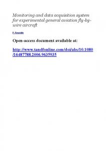
I. INTRODUCTION We have designed the Gamma Ray Energy Tracking In-Beam Nuclear Array (GRETINA). GRETINA is based on germanium detectors and it will be capable of determining the energy and position (within 2mm) of the points of interaction of the gamma-rays with the germanium crystal and of tracking multiple gamma-ray interactions [1], [2]. GRETINA is composed of seven detector modules, each with four high purity germanium crystals (see Fig. 1), comprising a quarter or 1-π of a sphere. The detector module components include charge sensitive amplifiers [3] assembled inside the detector enclosure to instrument each of the 36 segments and the central contact. The gamma ray interaction with the germanium crystal induces charge on the segments and central contact. The amplifiers integrate this charge and drive an Manuscript received November 15, 2007. This work was supported by the Director, Office of Science, Office of Nuclear Physics, of the U.S. Department of Energy under Contract No. DE-AC02-05CH11231. Renato Brito, was with Lawrence Berkeley National Laboratory. He is now with the Department of Electrical Engineering, Federal University of Rio Grande do Sul, Porto Alegre, RS 90035 Brazil. D. Doering, B. Holmes, J. Joseph, H. Yaver, S. Zimmermann are with Lawrence Berkeley National Laboratory, Berkeley, CA 94720. John T. Anderson, Todd Hayden are with Argonne National Laboratory, Argonne, IL 60439. Corresponding author: Sergio Zimmermann, phone 510-495-2964, e-mail:
[email protected].
1-4244-0923-3/07/$25.00 ©2007 IEEE.
analog voltage to the GRETINA front-end electronics. There are plans to construct the full 4-π detector module array, GRETA [4], and the electronics system foresees this possible scenario.
Fig. 1. GRETINA Detector Module
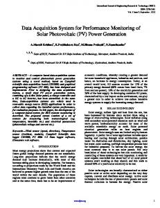
The detector modules are supported by a mechanical structure composed of two quasi-hemispheres shells that surround the target chamber. This shell structure is capable of supporting 21 detector modules. The structure allows rotation for detector mounting (through a gear box in the end of the axels) and translation to access the target chamber (through railroad cars). Hexapods connect the structure to the railroad cars. Fig. 2 shows a sketch of the support structure, with all possible positions instrumented with a detector module. In this paper the details of the electronics and algorithms of the GRETINA data acquisition and trigger system will be presented and the performance will be reviewed. In addition, grounding and filtering techniques used to achieve the 14-bit analog to digital conversion (ADC) performance will be discussed, as well as transmission line techniques for the very low bit error rate of the gigabit links. II. SYSTEM ARCHITECTURE Fig. 3 shows a block diagram of the GRETINA Electronics and Computing Systems. The oblong shape on the left represents the detector modules and its crystals. Charge sensitive amplifiers instrument the segments and central contact. Fifteen meters of shielded twisted pair cable connect the pre-amplifier outputs to the digitizer modules. Two custom designed modules, the Digitizer/Digital Signal Processing (Digitizer/DSP) and the Trigger Timing & Control (TTC), compose the electronics of this system. Four Digitizer/DSP modules instrument one crystal: each master Digitizer/DSP interfaces with the TTC system and controls three slave
1751
Digitizer/DSP modules. A digital bus in the front panel allows the digitizers serving a crystal to synchronize among themselves for clock and trigger information. A very simple communication protocol based on a single master controlling the operations is used. The master digitizer monitors the crystal central contact. If a gamma ray deposits charge in the crystal above the programmable threshold of the leading edge discriminator (LED), the master Digitizer/DSP recognizes the event and reads the segment hit pattern using the front panel bus. In parallel the Master digitizer estimates the energy of the central contact signal using a fast algorithm. It then assembles the trigger information (time stamp (TS) of the LED, central contact energy and segment hit pattern) and sends it to the TTC over one pair of a bidirectional 1Gb/sec serial link. A buffer records the timestamps of all recent discriminator decisions.
trigger decisions. The Master TTC collects all messages from the Routers plus additional information from auxiliary trigger modules and uses it to make a global trigger decision (refer to Fig. 4). Once a global trigger decision is made, the TTC system sends a trigger decision command to the Routers for distribution to all master Digitizer/DSP modules and auxiliary detectors. Each master Digitizer/DSP identifies a match between the timestamp embedded within the trigger decision message and the saved LED timestamps, and requests all slave Digitizer/DSP to transfer the data from the circular buffer into its own readout FIFO. Later, the VME readout CPUs in the digitizer crates read the event data from each Digitizer/DSP FIFO, assemble the crystal event, and send the data to the network switch. The switch routes the events to the farm where they are processed. The processing uses the segment information to estimate the position (r,θ, z) and energy of the interaction points. Additional processing establishes the tracks by connecting the individual interaction points.
Quasihemisphere shell Crystal
Detector module
Digitizers
Pre-amplifier
Readout CPU
2.2 MB/s
Rotation control
Axel Trigger and Timing Modules 28 Crystals
Network Switch
Processing Farm & Data Storage
Aux. Det. Trigger
Aux. Det. Data
Railroad car
Hexapods
Fig. 2. GRETINA Mechanical Support Structure
Fig. 3. GRETINA Electronics and Computing Systems
The serial link connecting the TTC and Digitizer/DSP modules is implemented using the National Semiconductor DS92LV18 Serializer/Deserializer (SerDes). It transmits 20 bits per word at a 50 MHz rate, where 18 bits are available to transmit trigger and control information. The link has stable (within the requirements) and predictable latency. The predictable latency allows the same twisted pair to both transmit control information and provide the 50MHz master clock to each Digitizer/DSP. The trigger information exchange between the master trigger and Digitizer/DSP employs a synchronous protocol and the master trigger module determines the synchronism. The protocol consists of an endlessly repeating series of 20 command frames transmitted every 2 μs that allows the TTC system to regularly synchronize and control activities at the Digitizer/DSPs. Conversely, all trigger information from the Digitizer/DSP is transmitted to the TTC within this 2 μs. A synchronous implementation like this is easier to implement and maintain. The whole TTC system is assembled around the same hardware module. The firmware is configured for two different functions: the Router module and the Master TTC. The Router routes all information between the Master TTC and the Digitizer/DSP modules and assists in fast multiplicity
We have extensively tested the performance of the DS92LV18 SerDes for bit error rate (BER). We have measured BER better than 10-16, which corresponds to less than one error per day for GRETINA (four per day for GRETA). This component is a very simple SerDes that adds minimum protocol (an important characteristic for the constant latency). We observed that adding external FPGA logic to execute the DC balancing of the communication and replacing the cable from unshielded CAT5 to a good quality shielded CAT5 significantly decreased the BER from one error every few hours to the level reported above. LVDS drivers with programmable pre-emphasis are used in all modules to compensate for cable losses. Each Digitizer/DSP and TTC module is implemented using two field programmable gate arrays (FPGA): one is a smaller FPGA, which controls the VME interface and has a steady configuration, and the other is a larger FGPA which executes the module specific algorithms and is easily re-configured through VME.
1752
the 50 MHz master clock distributed from the TTC. This results in approximately 20 giga-operations/s. While the processing occurs, the raw data is stored in 40 μsec circular buffers (designed around the FPGA block RAMs). GRETINA DIGITIZER BLOCK DIAGRAM FRONT PANEL INDICATORS
100MHz CLOCK DIST
CENTRAL CONTACT OUT EVENT FIFO CH0 FE/ADC
MAIN FPGA
CH1 FE/ADC
(1MB)
VME CTRL &
XC3S5000-5FG900
I/O
(633 USER I/O) CH9 FE/ADC
DAC OUT EXT CLOCK IN SER/DES IO
50MHz REF CLK
50MHz RCLK
FRONTBUS IO
CONTROL
3:1 MUX
AUX IO (11)
Fig. 6. Digitizer/DSP Block Diagram Fig. 4. TTC Router and Master Connection TABLE I DIGITAL SIGNAL PROCESSING
III. DIGITIZER/DSP The Digitizer/DSP module samples the crystal segment and central contact analog information using 14-bit ADC operating at 100 Msamples/s. The ADC used is the AD6645 from Analog Devices. Fig. 5 shows a picture of the module and Fig. 6 shows its block diagram. The Digitizer/DSP has a total of 10 analog inputs. The ADCs are connected to an FGPA, which digitally processes the conversion and executes the following operations: leading and constant fraction discrimination, trapezoidal filtering, energy determination, and pole/zero cancellation.
Leading Edge Discrimination y(n)=x(n) – x(n-k) (differentiation) y(n)=(x(n) + x(n-2)) + x(n-1)