J. Astrophys. Astr. (2006) 27, 299–304
Data Acquisition, Control, Communication and Computation System of Solar X-ray Spectrometer (SOXS) Mission Amish B. Shah1,∗ , N. M. Vadher1 , Rajmal Jain1 , Hemant Dave1 , Vishal Shah1 , K. S. B. Manian1 , Satish Kayasth1 , Vinod Patel1 , Girish Ubale1 , Kirit Shah1 , Chirag Solanki1 , M. R. Deshpande1 , Ramkrishna Sharma2 , C. N. Umapathy2 , N. Viswanath2 , Ravi Kulkarni2 , P. S. Kumar2 1
Physical Research Laboratory, Navrangpura, Ahmedabad 380 009, India. ISRO Satellite Application Centre, Vimanapura, Bangalore 560 017, India. ∗ e-mail:
[email protected] 2
Abstract. The Solar X-ray Spectrometer (SOXS) mission onboard GSAT2 Indian Spacecraft was launched on 08 May 2003 using GSLV–D2 rocket by Indian Space Research Organization (ISRO). SOXS aims to study solar flares, which are the most violent and energetic phenomena in the solar system, in the energy range of 4–56 keV with high spectral and temporal resolution. SOXS employs state-of-the-art semiconductor devices, viz., Si-Pin and CZT detectors to achieve sub-keV energy resolution requirements. In this paper, we present an overview of data acquisition, control, communication and computation of low energy payload of the SOXS mission. Key words.
Data acquisition—X-ray spectrometer—instrumentation.
1. Introduction Solar flares are explosive phenomena and they release gigantic energy in the solar system and thereby affect the Earth’s environment and interplanetary space. Thus understanding solar flares is of the highest priority. The Solar X-ray Spectrometer mission is a step in this direction, in order to understand the energy release and particle acceleration mechanisms. The science objectives and instrumentation of the SOXS mission are described by Jain et al. (2000a, 2000b, 2002a, 2002b, 2005). X-ray spectroscopy of solar flares demands complex and state-of-the-art instrumentation. The solar corona is very hot, up to 5 keV and therefore X-ray flux in general is high and particularly during flares it becomes very high, while in high energy band (>10 keV) it starves for photons. Thus the designing of X-ray spectroscopy instrumentation, its operation and control becomes very complicated. We optimized the system in the dynamic energy range of 4–56 keV with the application of two detectors namely Si and CZT in order to observe almost all classes of flares and with satisfactory performances of the detectors. In section 2, we present very briefly data acquisition, control and communication aspects, while in section 3, we conclude our discussion. 299
300
Amish B. Shah et al.
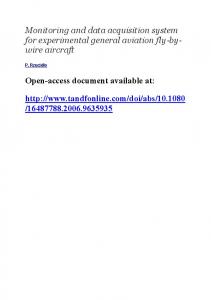
Figure 1. Block diagram shows SOXS low energy detector (SLD) subsystems. The signal flow from detector to telemetry packages is shown.
2. Instrumentation In Fig. 1, block schematic of the low energy payload of SOXS mission is shown. The system consists of the following sub-systems: • Low Energy Detectors (SLED) package consists of Si-Pin and CZT detectors. • Front end Electronics (SFE) package consists of analog processing electronics. • Low energy processing Electronics (SLE) package consists of data acquisition and control electronics. • Common Electronics (SCE) package consists of power and communication electronics. • Telemetry (TM), Tele command (TC) and Transmitter (TX) interface for spacecraft bus. We discuss briefly the salient features in the following sections 2.1 Low energy detectors This SLED package includes Si-Pin and CZT detectors with thermoelectric cooler, Charge Sensitive Pre-Amplifier (CSPA), high voltage dc–dc converters and heaters (Jain et al. 2002b). The detectors are mounted with collimators to restrict field of view to obtain better S/N ratio and to attenuate high energy charge particles. Each collimator has on-board calibration source for periodic calibration of the instrumentation. The details of the payload instrumentation is described in Jain et al. (2002a, 2002b, 2005). The SLED package is mounted on Sun Tracking mechanism (SSTM). SSTM controls SLED movement in RA and DEC axis with the help of single stepper motor which is
Solar X-ray Spectrometer (SOXS) Mission
301
a very novel approach Viswanatha (2000). The SSTM is capable of positioning SLED with 0.1 deg. accuracy and can be controlled from ground station with the help of tele commands. Sun Sensors (SSS) are mounted on SSTM to get absolute position of the Sun. Two thermistors are also mounted on SSTM to monitor the absolute temperature of packages. The SLED is powered by SCE and the output signals of detectors and temperature sensors are provided to SFE for further processing. 2.2 Analog processing This package includes linear pulse shaping amplifier, peak detectors, 8-bit ADC, energy window discriminator, telemetry interface for housekeeping (HK) parameters, temperature and corona auto-shut-off electronics (Jain et al. 2000b). Pulse shaper and amplifier circuit consists of three stages of pulse integrating amplifiers. Analog pulse from SLED is shaped and amplified by this stage. Amplified pulse is compared with the Lower Level Discriminator LLD (4 keV) and Upper Level Discriminator ULD (25 keV for Si-PIN and 60 keV for CZT) signals. The comparators derive trigger output (Strobe pulse) if the input signal is within LLD–ULD range. This strobe pulse is the heart of SFE and used for event time generation. Amplified signal of pulse shaper is split into two channels (1) high spectral resolution (82 eV/ch for Si-Pin and 212 eV/ch for CZT) ADC channel and (2) high temporal resolution (60 kps) window channel. Energy of pulse is classified into totally nine ranges to use them for flare detection logic. Package health is monitored by 1 kHz telemetry. 16 parameters are monitored every 16 sec through LBT. The parameters monitored are detector temperatures, SFE dcreferences and salient threshold voltages. Total events recorded in both detectors are also monitored by telemetry. Temperature auto-shut-off circuit switches off the detector bias voltage when the detector temperature falls out of the operating temperature range of −25◦ C to +5◦ C. This will protect the detector from thermal breakdown. Corona auto-shut-off circuit switches off the detector bias when the detector bias current increases 50% above the normal value. 2.3 Data acquisition and control This package consists of 16-bit window counters, ADC interface, real-time pulse height analysis (PHA) logic, 5 MB on-board memory to store flare and HK data, On-Board Timer (OBT) and telemetry and telecommand interfaces (Umapathy et al. 2003). The PHA generates real-time histogram from ADC data and stores it in PHA memory. The PHA memory is flushed every sampling time to on-board flare memory. The timing logic generates all required time in such a way that each event is processed within 20 µsec. The nine window pulses are gated to nine 16-bit counters. These counters are sampled continuously to decide flare on-set and stored every sampling time to on-board flare memory. Two out of nine counters are used and compared with uplinkable thresholds to decide about quiet or flare phase. SFE HK parameters are routed to telemetry via processing electronics. The SOXS processing electronics has a total of 5 MB on-board memory divided into two banks each of 2.5 MB. The instrumentation provides ‘a continuous data recording and playback’ mechanism. When one bank is busy with acquiring data the other is
302
Amish B. Shah et al.
flushing data to telemetry at 8 kHz rate. The banks are switched every 29.8 minutes for data acquisition. On-board 16-bit CPU controls all operations of processing electronics. The SOXS current operating mode is programmable via telecommand. Operating modes are: • • • •
Flare mode (search, quiet and flare integrated), Survey/background mode (100 ms and 1 s), Memory and electronics check-out mode, Readout mode.
Flare mode is the normal operating mode. In this mode, search is going on for flare onset. Quiet phase PHA and counters data are stored every 3 s and 1 s respectively. If flare is detected then data stores every 100 ms. The quiet and flare phases data are packaged into 700 bytes packet. The packet consists of: • • • •
Header (packet ID, time tag, flare status) information, Pulse height analysis (real-time spectrum) information, Energy window counters (temporal) information, Padding information.
Survey mode is used to study the level of background noise of quiet sun. This helps to estimate correct thresholds for flare detection. Memory check-out and read out modes are usable for on-board diagnosis. 2.4 Data communication This package provides a common interface to all SOXS packages with spacecraft bus. It minimizes the chance of damage of mainframe bus because of anomaly in packages. This package consists of low voltage dc/dc converters, high current ART converters, power electronics, telemetry/telecommand interfaces, base band data coder, convolution encoder, pre-modulation filter, sun sensor and SOXS mechanism drive electronics (Sharma et al. 2000). Two sets of RMUs and digital MUX provide common telemetry interfaces to SLED, SFE and SLE packages. Convolution encoding is an error correction technique used in data communication. This encoder can be bypassed by telecommanding in case error correction is not required. All high bit rate (HBT) and low bit rate (LBT) telemetry interfaces are conditioned in this package for final transmission to spacecraft telemetry. Telecommand received by spacecraft will be first received by this package and decoded and DEMUXed for respective packages. 2.5 Data computation The 700-byte packets are continuously uploaded to Master Control Facility (MCF) at Hassan, India. The packet is again combined with other monitoring parameters at MCF and 1248-byte packets are formed. The final packet consists of: • Frame ID (sync. bytes, data ID, frame counter), • Data packet status,
Solar X-ray Spectrometer (SOXS) Mission
303
• Derived and current PID values (parameters at onboard and current time), • Frames Ground Reception Time (GRT), • Dummy bytes. The 1248 packet consists of housekeeping parameters and flare data. The MCF computer is linked to PRL through space net. Space net is the dedicated 64 Kbps peer-to-peer network commissioned for space data interchange within ISRO units. The following computation is done on raw data. • • • • • • •
Extraction of health parameters, Instrumental correction, Validation of data w.r.t. health parameters, Averaging and construction of spectra, Gaussian/linearity curve fitting, Effective area calculation/energy calibration, Detector response fitting.
The IDL package installed on Linux enabled PCs are mainly used for off-line data computation. 3. Conclusion The SOXS mission was successfully launched, and in-orbit tests were conducted successfully. On-board subsystem parameters were evaluated and found satisfactory as per requirements. ∇T of the detectors found lower than predicted from thermal design restricts observing duty cycle to 3.5 h only. Satellite grounding noise shift CZT spectrum by 4 keV which restricts dynamic range to 4–56 keV. Apart from these detectors, analog processing, data acquisition, control and communication subsystems performance were found very satisfactory. References Jain, Rajmal, Rao, A.R., Deshpande, M. R., Dwivedi, B. N., Manoharan, P. K., Seetha, S., Vahia, M. N., Vats, H. O., Venkatakrishnan, P. 2000a, Bull. Astron. Soc. India, 29, 117. Jain, Rajmal, Deshpande, M. R., Dave, H. H., Manian, K. S. B., Vadher, N. M., Shah, A. B., Ubale, G. P., Mecwan, G. A., Trivedi, J. M., Solanki, C. M., Shah, V. M., Patel, V. D., Kayasth, S. L., Sharma, M. R., Umapathy, C. N., Kulkarni, R., Kumar, Jain, A. K., Sreekumar, P. 2000b, Technical Document – “GSAT-2 Spacecraft – Preliminary Design Review (PDR) Document for Solar X-ray Spectrometer”, ISRO-ISAC-GSAT-2-RR-0155. Jain, Rajmal, Dave, H. H., Vadher, N. M., Shah, A. B., Ubale, G. P., Shah, V. M., Solanki, C. M., Kayasth, S. L., Patel, V. D., Shah, K. J., Deshpande, M. R. 2002a, PRL Technical Document “Characterization and Response of Si PIN and CZT Detectors”, PRL-GSAT-2-SOXS-0180. Jain, Rajmal, Dave, H. H., Vadher, N. M., Shah, A. B., Ubale, G. P., Shah, V. M., Solanki, C. M., Kayasth, S. L., Patel, V. D., Pabari, Jayesh, Shah, K. J., Panchal, G. A., Deshpande, M. R. 2002b, PRL Technical Document “Configuration Design Review (CDR) Document of SOXS Low Energy Detector (SLED) Package”, PRL-GSAT-2-SOXS-0181. Jain, Rajmal, Dave, H. H., Vadher, N. M., Shah, A. B., Ubale, G. P., Shah, V. M., Shah, K. J., Kumar, S., Kayasth, S. L., Patel, V. D., Trivedi, J., Deshpande, M. R. 2003, PRL Technical Document “Pre-flight Characterization and Response of the SLD/SOXS Payload”, PRLGSAT-2-SOXS-0185. Jain, Rajmal, Dave, H. H., Shan, A.B., Vadher, N. M., Shah, V. M., Ubale, G. P., Manian, K. S. B., Solanki, C. M., Shah, K. J., Kumar, Sumit, Kayasth, S. L., Patel, V. D., Trivedi, J. J., Deshpande, M. R. 2005 Solar Phys., 227, 89.
304
Amish B. Shah et al.
Sharma, M. R., Umaptahy, C. N., Kulkarni, R., Kumar, Jain, A. K., Sreekumar, P. 2000, Technical Document, “GSAT-2 Spacecraft Preliminary Design Review (PDR) Document for Solar Xray Spectrometer” Part 2, ISRO-ISAC-GSAT-2-RR-0155. Umapathy, C. N., Sharma, M. R., Kulkarni, R., Kumar, Solanki, C. M. 2003, Technical Document, “GSAT-2 Spacecraft Design Document on the Processing Electronics for Low Energy Detector System-SOXS” ISRO-ISAC-GSAT-2-RR-0365. Viswanath, N. 2000, Technical Document, “GSAT-2 Spacecraft Preliminary Design Review Document (PDR) – Mechanisms”, ISRO-ISAC-GSAT-2-RR-0160.