DATA-CENTRIC SIMULATION INTEROPERABILITY USING THE DeST. SIMULATION ..... Inadequate Interoperability in the U.S. Capital. Facilities Industry.
Proceedings: Building Simulation 2007
DATA-CENTRIC SIMULATION INTEROPERABILITY USING THE DeST SIMULATION PLATFORM Yun Kyu Yi 1, Jaime Lee 1, Ali M. Malkawi 1, Chuang Wang2, Yi Jiang2, and Da Yan2 1 T.C. Chan Center for Building Simulation and Energy Studies, University of Pennsylvania, Philadelphia 19104, USA 2 T.C. Chan Center for Building Simulation and Energy Studies, Tsinghua University, Beijing 100084, China ABSTRACT Though architects are increasingly using building simulation, limitations in the interoperability of simulation domains remain a challenge. Independent simulations often have unique database structures. Incompatibilities between these structures render it difficult to share input and output data with other simulations, making it difficult for a designer to predict multiple aspects of building performance at the same time. The integration of algorithms provides one means of overcoming some of these limitations and of increasing the efficiency and prediction accuracy of performance tools. DeST (Designer’s Simulation Toolkit) is a custom environment in which multiple simulation engines are integrated into one system. This paper presents a newly developed IFC (Industry Foundation Classes)-based common database, the advantages and limitations of integration with DeST database structure and its object expansion to various domain integration will be discussed.
KEYWORDS DeST, IFC, XML, Integration, Coupling.
INTRODUCTION Computer-Aided Design (CAD) systems allow architects and engineers to create and share geometric data with each other. Advances in the interoperability of geometric data types have allowed increased freedom and flexibility in software choices; however, data types which are limited to geometric data are often incompatible with simulation software. In order to run building simulations such as structural analysis, thermal analysis, or HVAC (Heating Ventilation and Air Conditioning) analysis, users must often redefine geometry and boundary information within the specific simulation platform. Additionally, because the data types used by the various analysis software programs are often incompatible, users must redefine this geometric data for each type of building behavior they wish to investigate. The problem of interoperability and integration has been acknowledged, and studies have shown that in
the planning, engineering, and design phase alone, inadequate interoperability amounts in costs of $2.6 billion over one year. Of those, architects and engineers were responsible for $1.0 billion (Gallaher, 2004). Thus, there is potential for tremendous savings if interoperability can be improved. Research in interoperability has predominately involved issues of inter-model coupling based on engine and equation integration. As computational environments have shifted from procedural to objectoriented, simulation-based environments have followed this shift. Object-oriented code that supports modularity and inheritance allows simulations to be more flexible and expandable. The result of this shift is the “technical” potential to begin work on encapsulating, sharing, and distributing simulations. In addition, the development of environments and frameworks that can achieve design analysis integration based on semantic representations and support object and data interaction is now possible. This paper will discuss current developments in the data-sharing field and highlight the possibilities and limitations of various approaches, including the use of generic data structures such as IFCs. Strategies will be presented for one simulation platform in particular, DeST (Designer’s Simulation Toolkit). These strategies include IFC-compatibility in addition to a data sharing approach to integrate DeST with other domain simulations, such as coupling strategies for DeST with Computational Fluid Dynamics (CFD) and lighting analysis.
GENERIC DATA SHARING AND THE INDUSTRY FOUNDATION CLASSES Currently, several techniques are either in use or in development to integrate multiple simulation domains. Among them, three main approaches exist: the integrated model approach, the custom or specific data sharing approach, and the generic data sharing approach (Malkawi, 2004). The integrated model approach attempts to link or couple two or more simulation models. In the data sharing approaches, the engines themselves are not coupled, but the input and output data are common to two or more simulation models. With custom or
- 1587 -
Proceedings: Building Simulation 2007
specific data sharing, a custom-designed building information model is created with specific functionalities. With generic data sharing, the building information model is designed with the flexibility and breadth necessary to become a common data model. The generic data model must be able to provide information which can be used for a large variety of software, and the specific input and output data would be obtained by mapping the relevant information from the generic model to the data model type used by the specific application. Of all the approaches currently being used to increase interoperability, that with the most potential for universal interoperability is the generic data model approach. The ideal generic data model would contain all the necessary data to describe a Building Information Model (BIM). A BIM contains both geometric data and other essential information about the project, such as the materials, cost, and schedules associated with each geometric component, as well as information about individual spaces and the site. With purely geometric data models, entities such as “walls,” “apertures,” “spaces,” etc. are represented in terms of their geometric definitions. A BIM allows the user to specify the functionality of each geometric component, as well as relationships between each element. This additional data is critical if the information is to be used in simulation programs. The potential of the BIM has long been recognized, and in 1995, the International Alliance for Interoperability (IAI) was established with the mission of “providing a universal basis for process improvement and information sharing in the construction and facilities management industries” (IAI, 2006a). To achieve this goal, they have developed the IFC, a non-proprietary generic objectbased building information model. Over the past decade, multiple versions of IFC have been released, each with increased functionalities. The current version, IFC2x3, was released in February 2006. Since the original release in 1997, IFCs have become increasingly widespread, with the first commercially compatible software available as early as 1998, and the more recent versions allowing for module-based expansions and the introduction of XML (eXtensible Markup Language) definitions. The structure of the IFC model can be considered as four main layers: the resource layer, the core layer (extensions and kernel), the interoperability layer (shared elements), and the domain layer (Khemlani, 2004; Liebich et al., 2006). Information about the building is stored in objects called entities. Each entity in the IFC model has a given level and can only reference or be related to entities at the same or lower levels through a familial-like hierarchy. Entities inherit attributes from their super-types, so
that in the hierarchy, those entities in the lowest levels have all the attributes of each of the entities above them. IFCs are flexible in that it is possible to create new property sets called P-sets. If the descriptions available in the current IFC release do not adequately describe some aspect of a project, P-sets may act as temporary substitutes to the definition of object/ attribute/ relationship sets in the IFC model. If a Pset proves useful to a wider audience, it can become a regular set in future IFC releases. The IFC model clearly has tremendous potential to eliminate the interoperability problem, in that it is a generic data sharing type which is flexible enough to handle additions of new entities or properties. There are still numerous limitations to using IFCs, including the general lack of preparedness of the industry at large for such a model type, difficulties in populating the model with the correct data, limitations in the model’s definitions, and general software incompatibility (Bazjanac, 2002).
IFC-COMPLIANT CAD-BASED SOFTWARE: CURRENT CAPABILITIES AND LIMITATIONS The potentials of IFCs in the Architectural Engineering Construction (AEC) industry have been understood since the IAI’s inception, and many software companies have attempted to make their software IFC-compliant. The first of these included software used by architects to create geometrical representations of a design. Currently, four major cad-based software packages are IFC-compliant. These are Graphisoft’s ArchiCAD, Bentley’s Architecture, Autodesk’s Architectural Desktop, and Nemetcheck’s Allplan. Of these, ArchiCAD and Architecture are discussed in this paper. Graphisoft has fully integrated IFCs into ArchiCAD, defining the model as a “Virtual Building” in their software (Graphisoft, 2004). ArchiCAD allows the user to easily model commonly used elements and to define and edit their materials and construction types. ArchiCAD has a built-in library of materials and elements which, when selected, automatically generate data which is stored in the Virtual Building model and can be converted to an IFC model. ArchiCAD’s interface and architecture approach the BIM in the same way as the IFC model, as a group of connected objects, each with individual attributes and relationships. Interfaces within ArchiCAD allow the user to directly access the IFC model of the building, where the user can edit or populate data (Graphisoft, 2004). Additionally, the user can create custom Psets to describe an object if the standardized version does not provide an adequate description. ArchiCAD supports a large number of IFC entities and parameters. A full list can be viewed in Appendices
- 1588 -
Proceedings: Building Simulation 2007
A-D of the ArchiCAD IFC 2x Edition 2 Reference Guide.
that file within fully compliant software such as Architecture can lead to a tremendous loss of data.
Unlike Graphisoft, which has adopted a more holistic approach to the integration of IFCs into their software, Bentley has chosen a more selective and piecemeal approach for their Architecture software. Their “Build As One” (Bentley, 2006a) initiative supports the BIM as the optimum model for the AEC industry to work effectively and efficiently, while their “Commitment to Open Standards and Interoperability” (Bentley, 2006b) lists numerous standards to which the Bentley software will adhere, including multiple CAD formats, PDF, OpenDGN, and newer formats, in addition to IFCs. Bentley supports IFC property sets which are acknowledged as “common” by the IAI Model Support Group. For export to IFC, definitions of native Bentley architecture objects are mapped onto IFC entities. To handle and customize properties, one must download an IFC-specific DataGroup schema, which is then added to the data set native to Architecture (Bentley, 2006c).
IFCS AND SIMULATION SOFTWARE: USING IFCS WITH ENERGYPLUS
Though IFC-compatibility has been achieved and maintained by software such as ArchiCAD and Architecture problems still exist. For instance, our initial experiments suggested that the current versions of ArchiCAD and Architecture produce IFC files which are not compatible with each other, though both software packages are in the same stage of IFC-compatibility (currently in Step 1 of IFC R 2x3 certification). The reason for this is perhaps because ArchiCAD is currently compliant with IFC R 2x2, while Bentley chose not to achieve certification for that particular IFC release for their Architecture software, instead certifying Architecture as IFC R 2x and reserving IFC R 2x2 certification for programs such as Building Electrical Systems. Additionally, though both ArchiCAD and Architecture are compatible with traditional CADbased software, and though both are IFC-compliant, it is difficult to convert geometry created in CADbased software to an IFC file. Our initial experiments indicated that when solids were created in a 3D geometry program such as Rhinoceros and imported into a program with more complicated features, such as ArchiCAD or Architecture, though the form of the geometry was preserved, the solidity or representation of each solid form was lost. The imported files contained only a series of lines, each of which had no necessary relationship or connection to any other. Thus, a solid “wall” became a set of twelve lines, which were each treated as a separate object. It is impossible to apply materials or construction attributes to such objects, and thus exporting these geometries to an IFC file led to decreased information rather than the opportunity for increased information. Additionally, it has been noted that even saving to an IFC file and re-opening
EnergyPlus is the first building energy performance simulation model able to import data directly from a BIM that describes a given building in IFC format (Bazjanac and Maile, 2004). EnergyPlus models energy flows within a building using a thermal zone algorithm over time in increments determined by the user (DOE, 2006a). EnergyPlus uses three main types of data as input: weather data, the Input Data Dictionary (IDD), and the Input Data File (IDF). The IDD gives a definition of the data field, including name, type of variable, min and max values, acceptable units, etc. The IDF is the main data file and is created by interfaces external to EnergyPlus. The IDF is divided into “classes” or groups of objects and their parameters (for example, “Surfaces,” “Zones,” “Schedules,” etc.). After the user selects an IDF file to run in EnergyPlus, the EnergyPlus Input Processor checks the IDF against the IDD definitions. EnergyPlus will run if all IDF objects are within the bounds of the definitions provided in the IDD. Additionally, because EnergyPlus is divided into modules, each individual model accesses data directly from the IDF using subroutines, which obtain only the input data relevant to that particular module (DOE, 2006b; DOE, 2006c). Although IDF files are native only to EnergyPlus, attempts have already been made to map common BIM model data files, such as an IFC, into an IDF file for use in EnergyPlus. The “IFCtoIDF” utility, developed at the Lawrence Berkeley National Laboratory, is a tool which achieves this conversion for certain geometric components of an IFC model. The IFCtoIDF utility extracts the IFC classes ifcBuilding, ifcBuildingStorey, ifcSpace, ifcWall, ifcWindow, ifcDoor, ifcFloor, and ifcRoofSlab. It then maps these objects onto their counterparts in IDF, defined as IDD objects designated as Building, Zone, Floor Surface, Ceiling Surface, Roof Surface, Wall Surface, Window Sub-Surface, and Door SubSurface. The utility does not convert precise materials or construction data but instead uses a small set of default materials, which are assigned to the converted geometries. Interior and exterior surfaces are understood; however, thermal zoning may not be fully accurate because IFC-compliant programs do not support consistent user input for thermal zoning information (Hitchcock, 2004; Karola, Antti, et al., 2001). The IDFtoIFC utility requires a middleware program, the BSPro COM-Server, in order to function correctly. The BSPro COM-Server was developed to
- 1589 -
Proceedings: Building Simulation 2007
allow programs to exchange IFC-compliant data without the necessity of extracting and replacing data in a complex IFC model. It acts as an interface to the IFC model, providing easier access to each IFC entity and its attributes (Karola, Antti, et al., 2001). The BSPro COM-Server is an integral part of the IFCtoIDF utility. In previous releases of EnergyPlus, the IFCtoIDF utility was available as an optional utility for download with EnergyPlus itself. During this time, the BSPro COM-Server was downloaded automatically with EnergyPlus if the IDFtoIFC utility was also selected for download, and a license for use of the BSPro COM-Server was automatically given free of charge. Another limitation of the IFDtoIDF utility is that EnergyPlus could not map the simulation results back into the original IFC file. However, another utility developed by the Lawrence Berkeley National Laboratory, the IFC HVAC utility, creates the potential to map data back into an IFC file. This utility, first released in 2003, maps HVAC entities from an IFC model to an IDF model. Similar to the IFCtoIDF utility, a middleware program is used as an interface to the IFC model, the IFC SECOM 2003. The HVAC utility is a critical step in achieving IFC interoperability with EnergyPlus because it also allows the user to export the HVAC data from EnergyPlus into a non-native BIM. If the data is used with the IFCtoIDF utility, one could bring both geometric and systems data from an IFC model directly into EnergyPlus, and additionally bring HVAC data from EnergyPlus back into the original IFC model (Bazjanac and Maile, 2004).
THE DeST PLATFORM DeST is a simulation program developed to assist engineers and designers to understand building energy performance. DeST was developed by the Institute of Building Environment and Building Services at Tsinghua University, Beijing, China, in the early 1990s. It has been applied to many projects in China and its results have been validated and documented (DeST, 2007).
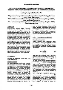
Figure 1 Structure of DeST.
As indicated in Figure 1, the structure of the DeST program is module-based, allowing easy expansion and addition of features. DeST includes several simulation engines into one combined system, providing interoperability between the various tools using shared custom data objects. It supports integrated environments for multi-simulations using a common object data representation and allows concurrent simulations to be executed. The DeST modules include CABD (Computer Aided Building Description; User Interface), Medpha (Meteorological Data Producer for HVAC Analysis; Climate Data), BShadow (Shadow Simulation), Lighting simulation (Illuminance Calculation), VentPlus (Ventilation simulation), BAS (Building Analysis & Simulation; Thermal Temperature and Air Conditioning Load), Air Conditioning System simulations, and an Economic model. Each module has a specific function that allows for the analysis of one aspect of building performance. CABD (User Interface) is CAD-based and is used to generate and modify geometric models. Medpha (Climate Data) includes the measured weather data of 270 Chinese cities over 30 years, and it produces the climate data necessary for building simulations. The ventilation simulation combines the natural and mechanical ventilation with network theory. The economic model provides an accurate economic evaluation of the mechanical system of a building. DeST has two inputs and four outputs. Inputs include building information and systems information. The outputs indicate illumination, ventilation, thermal, and energy consumption. Similar to current major building simulation tools, DeST was also developed as a custom data sharing approach so that within the DeST system, data can be shared by multiple domains. However, there are limitations on importing and exporting data to independent third party tools.
NEW DATA SHARING STRATEGY FOR DeST Several issues were identified in the development of IFC data sharing in geometry modeling and building simulation. These difficulties include: converting geometry created in a CAD-based software to an IFC file, populating the IFC model with the data necessary for the simulation, and mapping the simulation results back into the original IFC file. To integrate DeST with different simulation domains, these issues must be resolved. To compensate for the issues mentioned above, it is imperative to locate a simple and accessible file format. The IFC model is currently defined using the EXPRESS language. Recently, the IAI developed an
- 1590 -
Proceedings: Building Simulation 2007
ifcXML implementation guide that discusses the specifics of an XML based implementation of the IFC object model, allowing IFC models to be defined using XML instead of EXPRESS (IAI, 2006b). XML has a broad range of supporting utilities and database implementations, and is the basis for most eCommerce messages and Web services. XML is also supported by XSLT (eXtensible Stylesheet Language Transformations) style sheets, making information immediately accessible on computer devices. Despite the current limitations of converting XML format to EXPRESS (IAI, 2006b), the potential possibilities of an XML based IFC included Internet friendliness, greater flexibility in a model’s definitions, and unlimited access from a broad range of utilities. These potentials motivated authors to develop a data sharing XML based format.
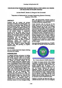
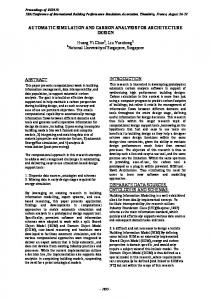
certain geometric and material components of an IFC model or XML based data model to the native DeST format. The results of the simulation can also be converted to XML format and can be exported. Once the model is converted to the recognizable DeST XML format, the file can be accessible by the DeST engine without additional conversions. It is also possible to edit the XML file in various XML accessible utilities without accessing the DeST interface. Figure 3 shows a simple model of one room with three windows (blue) and one door (red) in the DeST interface. This model was originally imported from an XML file.
To render DeST IFC-compatible, it is necessary to develop a utility to convert IFC files to the native DeST format. This is best accomplished in a similar manner to the EnergyPlus utility, by mapping geometry from the IFC model to the DeST model based on an XML format. In an IFC model, data are dispersed into separate modules such as the geometric resource, the material resource, the date-time resource, etc., which are interconnected in a complex way. Additionally, for most DeST simulations, the geometry of a model must be simplified in order for the simulation to run. Therefore, in order to use the IFC format with DeST, the IFC data itself must be reorganized, the geometry must be simplified, and the material properties must be selected and remapped from the IFC file to an recognizable format for DeST.
Figure 3. Sample geometry model shown in DeST. The following encryption of text indicates the geometric representation of the file in XML format: 408 . 409 411 413 257 1 0 Written in XML, files can be accessed from different utility programs. Figure 4 indicates the door’s information as accessed by MS Access and Internet Explorer. This feature will allow for the development of web-based simulation tools in the future.
Figure 2. Integration with XML. A new DeST structure, based on an XML format, is indicated as Figure 2. An IFC compatible file can be converted to an XML format and that XML based file is then sent to the XML format file converter. The converter is a tool that achieves conversion from
- 1591 -
Proceedings: Building Simulation 2007
provide a more accurate surface temperature to the simulation CFD. Figure 4. Door’s information in MS Access and Internet Explorer (DeST database).
INTEGRATION WITH DIFFERENT DOMAIN SIMULATIONS Even though developing a common data exchange is a good strategy, the question of what data have to be shared with different simulations remains a challenge. Each simulation shares certain variables and it is necessary to identify variables and determine when these variables have to be exchanged among simulation engines. In addition to investigating shared data bases, our goal has been to conduct inter-simulation coupling when necessary. Data sharing as described above will allow the creation of custom environments that facilitate the simulation engines' data sharing. To increase the accuracy of the predictions of the simulations and allow for negotiations between these simulations (eg. the influence of air movement on heat exchange), internal coupling is required. Currently, coupling strategies are in development for DeST with both CFD and lighting analysis. The following two sections describe the progress of this development. Coupling with CFD Recently, several research projects that couple Energy Simulation (ES) and CFD have been conducted. It is been shown that increased accuracy of the energy simulation results from such a coupling (Djunaedy, 2005; Beausoleil-Morrison, 2000; Zhai, et al., 2002; Zhai, et al., 2003). The coupling strategy for CFD with DeST is based on Djunaedy’s method (2005). The main concept of the DeST and CFD coupling is in the convection heat transfer on the internal surfaces, which can represent by: q i , conv = hi , conv (Ti − Ti , air ) (1) where; 2
q i , conv : convective heat transfer(W / m ) hi ,conv : convective heat transfer coefficient (W / m 2 K ) Ti : surface temperature( K ) Ti , air : air temperature near the surface( K )
Energy Simulations (ES) typically estimate the Convectional Heat Transfer Coefficient (CHTC) values using empirical correlations. By coupling ES and CFD, the CFD simulation calculates the CHTC value. This value is then used by the ES to calculate the convection heat transfer, which in turn may
The main coupling procedure occurs on every time step. During the calculation of the convection heat transfer coefficient (CHTC) of internal surfaces, the intelligent agent, the program that will developed for DeST, will check if a CFD call exists for that time step. If a call exists, the program will invoke the CFD simulation to derive the CHTC. The coupling mechanism consists of pre-CFD treatment, CFD simulation, and post-CFD treatment. If no call to the CFD simulation is made, the program will continue with another mechanism for defining the CHTC of the internal surface (i.e. using one of many available empirical correlations). The pre-CFD procedure takes advantage of the gopher run (Beausoleil-Morrison, 2000) that will classify the flow regime near each surface. The result of the gopher run is a set of non-dimensional numbers for each surface, indicating the flow regime of airflow on the surface: either forced, natural, or mixed convection. 0.1 CHTC empirical < CHTC CFD < 10CHTC empirical
(2)
where : CHTC empirical : CHTC from empirical correlation CHTC CFD : CHTC from CFD calculation
After the CFD simulation is conducted, the post-CFD procedure will calculate the CHTC for each internal surface based on the CFD result. The calculated CHTCCFD is then compared to a CHTCempirical value calculated by the ES. If the CHTCCFD is not in the range of equation (2), it will be rejected, and the thermal domain will continue the calculation using the CHTC derived from the ES program. Coupling with Lighting Simulation Another coupling strategy currently in development is the coupling of DeST with a lighting simulation. At present, DeST has a lighting simulation module able to calculate daylight factors. This is done by data sharing with BShadow, which also included with the DeST modules. BShadow considers all the shadow cast factors such as surrounding buildings, the building itself, overhangs and side fins, and it uses geometric projection methods to calculate the shadow cast on the surface of the buildings. Based on the shadow calculation results for windows from BShadow, the daylight factors for each room under different sun positions can be obtained by lighting simulation, which is an efficient method to analyze an overall indoor lighting strategy. For a physically accurate and comprehensive lighting analysis, it is necessary to include a radiosity analysis to study the radiation distribution on the building’s interior.
- 1592 -
Proceedings: Building Simulation 2007
To include the radiosity component, the current strategy is to output data files from DeST which can be directly accessed by the RADIANCE Lighting Simulation Software. RADIANCE is a radiositybased lighting simulation tool written by Greg Ward at Lawrence Berkeley Laboratories and the DOE in the US. It is freely available for MS Windows as Desktop Radiance. The coupling method with RADIANCE will be a static coupling process, allowing information exchange between DeST and RADIANCE at any specific time step when the user desires a more detailed radiant study. Figure 5 shows the process of calling the RADIANCE core module to calculate detailed lighting analysis. DeST supports the automatic generation of material data and control files (RIF files), as well as various CIE sky models for RADIANCE. The materials created from DeST include only color, reflectivity, and roughness properties. However, one can add materials with more textures and surface properties in DeST’s XML file and export to RADIANCE.
file to a recognizable file for use by the simulation program. Additionally, it may be difficult to map the simulation results back into the original IFC file. Using DeST as an example of a building simulation program, this paper focused on locating an efficient and precise algorithm for mapping between DeST and XML-formatted data. The current plan for DeST is to develop it as an open platform reference on IFCs and extended it by utilize coupling algorithms.
REFERENCES Bazjanac, Vladimir. 2002. “Early Lessons from Deployment of IFC Compatible Software.” Proceedings of the European Community Product and Process Modeling Conference, May 2002, Portoroz, Slovenia. Bazjanac, Vladimir, and T. Maile. 2004. “IFC HVAC Interface to EnergyPlus – A Case of Expanded Interoperability for Energy Simulation.” Proceedings of Building Simulation, August 2004, Boulder, Colorado. Beausoleil-Morrison, Ian. 2000, “The Adaptive Coupling of Heat and Airflow Modeling within Dynamic Whole-Building Simulation.” Ph.D. Thesis, University of Strathclyde (United Kingdom). Bentley A http://www.bentley.com/enUS/Promo/Build+As+One/ Bentley B http://www.bentley.com/enUS/Markets/Building/Open+Standards+and+Int eroperability.htm
Figure 5. Lighting analysis with RADIANCE.
CONCLUSION IFCs have tremendous potential for achieving interoperability among software in the AEC industry. Since the IAI’s inception and the introduction of the IFC model, many major software companies have developed IFC-compliant software with which one can easily generate, populate, and edit IFC models. IFC input to building simulation engines has begun with the development of two utilities, IFCtoIDF and IFC HVAC, both of which allow the user to use an existing IFC model to run EnergyPlus. In addition, the IFC HVAC utility can export HVAC data from EnergyPlus into an IFC model. However, numerous obstacles also must be resolved. In this paper, several issues were discussed such as populating the model with the correct data, limitations in the model’s definitions, and general software incompatibility. Also, for use with building simulation software, it may be difficult to convert the geometry and embedded properties created in an IFC
Bentley C, 2006. “IFC Position Paper.” White Paper.
Bentley
DeST (Designer’s Simulation http://www.dest.com.cn/
Toolkit)
Djunaedy, Ery. 2005. “External Coupling between Building Energy Simulation and Computational Fluid Dynamics.” Ph.D. Thesis., TU/e, Eindhoven (The Netherlands). Gallaher, Michael P., et al. 2004. “Cost Analysis of Inadequate Interoperability in the U.S. Capital Facilities Industry.” NIST GCR 04-867. National Institute of Standards and Technology. Graphisoft. 2004. “ArchiCAD IFC 2x Edition 2 Reference Guide,” Draft Version 3.5. Hitchcock, Rob. 2004. “IFC to IDF Version 1.2.18 beta BSPro COM-Server Client for EnergyPlus: Acquiring Geometry form IFC for EnergyPlus.” IFCtoIDF User Documentation. Lawrence Berkeley National Laboratory. International Alliance for Interoperability (IAI) A http://www.iai-international.org/index.html.
- 1593 -
Proceedings: Building Simulation 2007
International Alliance for Interoperability (IAI) B, 2005. “ifcXML Implementation Guide, version 1.0” . Karola, Antti, et al.. 2001. “BSPro Com-Server – Interoperability Between Software Tools using Industry Foundation Classes.” Proceedings of Building Simulation, August 2001, Rio de Janeiro, Brazil. Khemlani, Lachmi. 2004. “The IFC Building Model: A Look Under the Hood.” AECbytes Feature. Liebich, Thomas et al. 2006. “IFC 2x Edition 3 Model Implementation Guide.” International Alliance for Interoperability Modeling Support Group. Malkawi, Ali. 2004. “Developments in Environmental Performance Simulation,” Automation in Construction 13 (2004): 437 – 445. US
Department of Energy (DOE) A “EnergyPlus Engineering Reference.”
2006.
US Department of Energy (DOE) B 2006. “Getting Started with EnergyPlus”. US
Department of Energy (DOE) C 2006. “EnergyPlus Guide for Interface Developers”.
Zhai, Zhiqiang, et al. 2002. “On approaches to couple energy simulation and computational fluid dynamics program.” Building and Environment 37 (2002): 857-864. Zhai, Zhiqiang and Qingyan Chen. 2003. “Solution characters of iterative coupling between energy simulation and CFD programs.” Energy and Buildings 35 (2003): 493-505.
- 1594 -