REVIEW OF SCIENTIFIC INSTRUMENTS
VOLUME 75, NUMBER 11
NOVEMBER 2004
Data coding tools for color-coded vector nanolithography Janusz Lekkia) Department of Nuclear Spectroscopy, Institute of Nuclear Physics, Cracow, Poland
Saveen Kumar, Sunil S. Parihar, Sebastien Grange, and Charles Baur Virtual Reality and Active Interfaces Group, Ecole Polytechnique Fédérale de Lausanne, Switzerland
Raphael Foschia and Andrzej Kulik Nanomechanics and Tribology Group, Ecole Polytechnique Fédérale de Lausanne, Switzerland
(Received 5 May 2004; accepted 3 August 2004; published 1 November 2004) We propose and demonstrate the ability and efficiency of using a universal file format for a nanolithography pattern. A problem faced by the physicists working in the field of nanolithography is a lack of a flexible pattern design software (possibly open–source) that could be applied in combination with a broad range of commercial scanning probe microscope (SPM) systems. The current nanolithography software packages are device–specific and not portable. Therefore, it is impossible to make a lithography pattern and share it with fellow physicists working on a networked sub-system. In this paper we describe the software designed to read and interpret a nanolithography pattern stored in a Windows Metafile (WMF) standard graphic format and next to draw it on a substrate using an SPM tip. The nanolithography parameters like height, velocity, feedback force, etc. are coded in the color of the WMF onto the RGB channels of the image establishing a distinct relation between a graphical feature (color) and the used nanolithography scheme (voltage, height, etc.). The concept enables preparation of complex patterns using any standard graphic software and aids an intuitive recognition of the mode and parameters set for a pattern. The advantages of using a WMF over other approaches and the universal scope of the software are discussed. © 2004 American Institute of Physics. [DOI: 10.1063/1.1805014]
I. INTRODUCTION
Scanning probe nanolithography1 allows a high resolution modification of a broad range of materials like metals, semiconductors, polymers, etc.2–6 However, the currently available nanolithography software packages used to design patterns that should be pictured on a processed surface offer a broad range of advanced, but somewhat restricted features. Additionally, all of them are system specific, which makes it difficult to share the pattern designed for a particular SPM system with a colleague working on a different system. Therefore, it seems to be reasonable to design tools allowing preparation of complex and sharable nanolithography patterns. The simplest approach – the use of bitmaps, JPEG, or similar images raises the question of effective vectorization and can be used conveniently at best for simple patterns. The solution of interfacing the SPM system with computer aided design7 is plausible to make complex patterns and vector nanolithography; however, a simplistic and more general solution would be more desirable. For example, the grayscale of a raster image has been successfully employed to control the voltage sent to the piezo driving cantilever oscillations for dynamic plowing nanolithography.8,9 This correlation enables a user to recognize the mode intuitively and, hence, ease browsing patterns. Subsequently the suggested implementation is presented together with the accompanying a)
Author to whom correspondence should be addressed; electronic mail:
[email protected]
0034-6748/2004/75(11)/4646/5/$22.00
software and a discussion on its advantages; several nanolithography examples obtained using two commercial SPM systems and developed software are shown. II. DATA FORMAT
A well established graphics standard WMF (Windows Metafile) was chosen as a data format for storing and subsequent interpreting of designed lithography patterns. A metafile is a collection of structures (records) that store a picture in a device-independent format. The graphics objects are stored as a series of graphics device interface (GDI) functions that are used to draw an image. Since all GDI primitives can be recorded, any image that can be drawn can be stored in a metafile. WMF guarantees high degree of device independence (unlike a bitmap) and both vector and raster options for lithography. The elements of a pattern are stored as geometrical units, i.e., points, lines, polylines, polygons, polypolygons rather than an array of colored pixels. This has a distinct advantage of being defined, concise, and easy to interpret for vector nanolithography and complex patterns. The color values in metafiles are stored as 24 bits RGB data which ensures device independence.10 Many WMF records are not relevant to lithography operation—so only the useful data dealing with geometries, color and image scale and origin are extracted while the rest are filtered out (Fig. 1). The program for pattern interpretation opens the metafile pattern, reads the metafile records one by one and processes only the records which hold informa4646
© 2004 American Institute of Physics
Downloaded 12 Jul 2006 to 128.178.251.7. Redistribution subject to AIP license or copyright, see http://rsi.aip.org/rsi/copyright.jsp
Rev. Sci. Instrum., Vol. 75, No. 11, November 2004
FIG. 1. The pattern prepared using any graphic software is interpreted. The code extracts relevant parameters from the code and sends it for nanolithography.
tion on geometrical elements of the pattern. Next, it combines the pattern information with the input data concerning SPM details like scanned image of the lithography substrate and hardware AFM constants (like scan size, microns per DAC, ranges… etc.), scales the pattern to microscope units and executes the geometries according to parameters. The final stage of pattern drawing is dictated by the nuances of the SPM system. The realization of the designed pattern with the use of an AFM is carried out either by producing a control input file (if a device may be controlled by a script language) or controlling the AFM dynamically. The first option is easier to implement, while the latter requires usually an in-depth knowledge of the AFM aimed at and the access to its source code/documentation.
Color-coded vector nanolithography
4647
FIG. 2. (Color online) The image shows how different colors will be interpreted by the SPM system. Red corresponds to feedback force, blue to bias voltage and green to tip height.
sified input data is required and parameters number must be increased, one has to lower the resolution by the color byte splitting. IV. INTERPRETATION OF DATA FORMAT
The prepared computer code allows interpretation of a metafile and converting its records into graphic primitives that are possible to realize using SPM control systems. The simplest geometry traceable by an SPM tip corresponds to a point or a line, i.e., the SPM can basically make a line by a
III. PARAMETERS CODING SCHEME
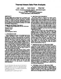
In soft nanolithography the four basic parameters must be taken into account when preparing a pattern: Feedback force, tip height, bias voltage, and tip velocity. The only software independent graphical property of a metafile that can be used to encode these parameters are the RGB color values: The color values in metafiles are stored as 24 bits RGB data. The parameters like line width and line type are neither convenient in use nor reliable. Therefore, a color scheme has been chosen where the 8-bit red component represents feedback setpoint, green represents vertical tip coordinate and blue represents voltage bias. The feedback force and tip height data cover the range from 16 to 255 and are mapped into a range 共−120. . . 0 . . . + 120兲. The zero value represents the sample surface. The remaining 16 low values serve as a container for the fourth parameter – the velocity of tip movement (Fig. 2). Such scheme is possible (and convenient) to use because the feedback and height SPM operation modes are mutually exclusive. The voltage data covers the range from 1 to 255 and is mapped into a range 共−127 0 + 127兲. The zero value represents voltage off condition. The above approach (two hi-res and one low-res parameter defining a lithography process) covers most of the practical requirements. However, in the case when a more diver-
FIG. 3. GDI functions are used to generate a WMF. On a computer display the overlapping figures are drawn as layers and are not mutually exclusive. Therefore, while interpreting the WMF and sending parameters to the microscope, same region may be written on more than once. This is acceptable if the user wishes to employ layered lithography (as in DPN). However, there has to be an alternative to treat overlapping geometries as mutually exclusive.
Downloaded 12 Jul 2006 to 128.178.251.7. Redistribution subject to AIP license or copyright, see http://rsi.aip.org/rsi/copyright.jsp
4648
Lekki et al.
Rev. Sci. Instrum., Vol. 75, No. 11, November 2004
FIG. 4. The solution to treat two overlapping regions as mutually exclusive for lithography is to “subtract” the region on top from the one below and treat it as the subtracted region for processing. This is possible using GDI functions in conjunction with our code. The above picture shows that the code can interpret even the most complex patterns. Two last stages of the image processing are shown as momentary snapshots taken during lithography simulation.
horizontal move between two points at fixed height or a point by a vertical tip movement at a specific coordinate. On the other hand GDI functions include polylines, polygons, and polypolygons which must be reduced to lines and points in order to be executable by the SPM system. A polygon function specifies the coordinates of the perimeter. This can be treated as a closed polyline and the contour can be converted into a series of interconnected straight lines. The fill is converted into a series of closely stacked,
nonoverlapping lines that strictly stay within the polygon’s perimeter. The program scans the bounding box of the polygon. The intelligence imparted to the program enables it to know when the probe enters or leaves the region area. The fill in the particular y co-ordinate is replaced by a straight line connecting the start and end point. During the nanolithography process the units of the WMF image are scaled down to the units of the scanned surface and, hence, the input pattern is fully zoomed to the scanned surface without distortion. V. FEATURES
The use of a WMF as a universal data format allows easy implementation of some important software features. The WMF stores images as a set of GDI functions. As the GDI functions use geometries instead of pixels, the pattern can be easily interpreted for Vector Nanolithography. However, some details must be taken into account: The GDI functions draw overlapping images on a computer display one on top of the other and not as mutually exclusive regions (Fig. 3). Therefore the data interpretation of a WMF with overlapping geometries will automatically lead to Layered Lithography. This can be useful for dip pen nanolithography (DPN).11 However, if the user wishes to treat overlapping geometries
FIG. 5. The GUI screenshot illustrating various functionalities and code options. The workspace is fully customizable.
Downloaded 12 Jul 2006 to 128.178.251.7. Redistribution subject to AIP license or copyright, see http://rsi.aip.org/rsi/copyright.jsp
Rev. Sci. Instrum., Vol. 75, No. 11, November 2004
as mutually exclusive, the solution is to “subtract” the region on top from the ones below and use subtracted mutually exclusive regions for processing (Fig. 4). The processing of WMF generates a text equivalent of the image called a runfile (*.run) and the pattern is also stored in form of an editable ASCII text file. Once produced from an original image pattern, this text file becomes an original image replica and the dedicated software can read this file to re-produce the image. The format is simple and can contain pattern specific data in a form the user may manipulate even without any graphics software. A simple representation of geometry enables the user to actually write the pattern “program” in absence of any graphic software without using any scripts or programming language. The runfile can be shared as easily as WMF, is system independent and gives an enhanced, direct control over pattern making. To enable dynamic change of parameters and efficient handling of information for the various features, the regions and lines are stored in a dynamic list. Regions (polygons and polygons) are stored with the handle, number of vertices, the vertices, fill color, contour color and region type. Line elements (point, line, polyline) are stored with number of vertices, vertices and line color. The list is re-created dynamically each time a new picture is analyzed and all changes are saved to the list and not to the image. VI. THE GRAPHICAL USER INTERFACE (GUI)
(Fig. 5.) The design of the interface has been largely participatory in nature due to active involvement of physicist in its development. The following features have been introduced to meet the user practical requirements and to solve the problems faced: (i) (ii) (iii) (iv) (v) (vi) (vii)
Possibility of dynamic changing the pattern and/or its parameters; an ASCII text file as the universal file format; inclusion/exclusion of the boundary contour of regions with the same or different parameters; a customizable interface; a display of a scanned image and all the relevant data; a visual demo before actual nanolithography; a possibility of an analysis of complex regions and option for layered lithography.
VII. RESULTS
The following examples show the application of M5, a Park Scientific AFM, used for nanolithography pattern drawing, where the AFM device was controlled by a script file. The PSI AFM uses an HDF file to store all the major constants and parameters of the particular scan like scan size, offset, setpoint, etc. The HDF contains a 256⫻ 256 grid of vertical 共z兲 coordinates for the corresponding horizontal 共xy兲 coordinates of the scan. To maintain a constant height from surface in case of uneven or sloped surfaces this data is very useful. The PSI AFM tip can trace only horizontal, vertical or 45 degree lines. A straight path for any other angle is traversed in two lines: One 45 degrees and the other straight.
Color-coded vector nanolithography
4649
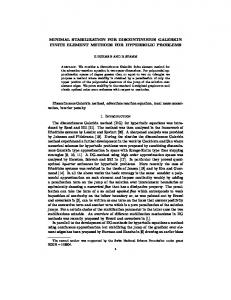
FIG. 6. (Color online) The figure (an AFM scan) displays a nanolithography pattern obtained using a WMF image. Green color corresponds to a constant height mode. Red value of color is 0, green value is 199, and blue is 0. This means feedback off, voltage off and height of 2.133 um (when the range for height is plus–minus 4.00 um and plus signifies that the probe moves towards the sample). The corresponding indentation made is displayed in the adjoining image. Microscope: PSI M5, sample: PMMA.
The approximation works perfectly for complex shapes since they specify a lot of vertices. Straight lines at other angles demand to be broken down into smaller segments for exact replication of the pattern. To demonstrate the potential of the proposed approach several test patterns have been designed and then used in a simple experiment where an AFM tip was scratching the polymer surface (similar performance was obtained also in the case of local oxidation experiments using a TiO2 substrate). Next, the modified surface was scanned and the resulting images are presented. Figure 6 shows poly (methylmethacrylate)(PMMA) surfaces modified to indent a spiral and the EPFL logo along with the corresponding WMF images used to generate them. All AFM scans and the nanolithography operations were carried out using M5 Microscope on a PMMA sample in constant height mode. The double lines in EPFL logo were caused by the indentation force (increased in comparison to a spiral)—the material removed from the track due to the scratching by an SPM tip was moved aside to the left and right, thus forming a double wall along the track. To make the patterns and save them as WMF files we have been using the Adobe Illustrator. However, WMF files may be produced using virtually any standard graphic software existing in Windows, Macintosh, and Unix worlds. VIII. FUTURE OBJECTIVES AND POSSIBILITIES
The unified, convenient pattern generation method for the nanolithographic applications not only may standardize
Downloaded 12 Jul 2006 to 128.178.251.7. Redistribution subject to AIP license or copyright, see http://rsi.aip.org/rsi/copyright.jsp
4650
the procedure (and thus facilitate the work), but also may support the idea of parallel nanolithography, where several devices are using the same input for pattern drawing. This latter job may be accomplished even using several microscopes over the network. Common input standard has many benefits, supporting, e.g., quick prototyping and / or exchange of results between different groups working in the field. ACKNOWLEDGEMENT
This work was supported by the Swiss CTI-TopNano21, Project No. 6028.2 1
Lekki et al.
Rev. Sci. Instrum., Vol. 75, No. 11, November 2004
M. Wendel, B. Irmer, J. Cortes, R. Kaiser, H. Lorenz, J. P. Kotthaus, A.
Lorke, and E. Williams, Superlattices Microstruct. 20, 349 (1996). E. Dubois and J.-L. Bubbendor, Solid-State Electron. 43, 1085 (1999). Z. J. Davis, G. Abadal, O. Hansen, X. Borise, N. Barniol, F. PerezMurano, and A. Boisen, Ultramicroscopy 97, 467 (2003). 4 S. Gwo, J. Phys. Chem. Solids 62, 1673 (2001). 5 R. Held, T. Heinzel, P. Studerus, and K. Ensslin, Physica E (Amsterdam) 2, 748 (1998). 6 Ph. Avouris, R. Martel, T. Hertel, and R. Sandstrom, Appl. Phys. A: Mater. Sci. Process. 66, S659 (1998). 7 S. Cruchon-Dupeyrat, S. Porthun, and G. Y. Liu, Nanofabrication using Computer-assisted Design and Automated Vector-scanning Probe Lithography (Elsevier, New York, 2001). 8 B. Klehn and U. Kunze, J. Appl. Phys. 85, 3897 (1999). 9 M. Heyde, K. Rademann, B. Cappella, M. Geuss, H. Sturm, T. Spangenberg, and H. Niehus, Rev. Sci. Instrum. 72, 136 (2001). 10 Microsoft articles Q66949, 145999, Q81497, 90291, http:// support.microsoft.com 11 M. Su and V. P. Dravid, Appl. Phys. Lett. 80, 4434 (2002). 2 3
Downloaded 12 Jul 2006 to 128.178.251.7. Redistribution subject to AIP license or copyright, see http://rsi.aip.org/rsi/copyright.jsp