Anadolu Üniversitesi Bilim ve Teknoloji Dergisi A- Uygulamalı Bilimler ve Mühendislik Anadolu University Journal of Science and Technology A- Applied Sciences and Engineering 2017 - Volume: 18 Number: 2 Page: 323 - 345 DOI: 10.18038/aubtda.270074 Received: 27 November 2016
Revised:30 March 2017
Accepted: 31 March 2017
DATA-DRIVEN TRAJECTORY UNCERTAINTY QUANTIFICATION FOR CLIMBING AIRCRAFT TO IMPROVE GROUND-BASED TRAJECTORY PREDICTION Mevlüt UZUN 1, *, Emre KOYUNCU 2 1
Controls and Avionics Research Group, Aerospace Research Center, İstanbul Technical University, İstanbul 2 Department of Aeronautics Engineering, Faculty of Aeronautics and Astronautics, İstanbul Technical University, İstanbul
ABSTRACT Efficient trajectory prediction tools will be the crucial functions in future trajectory-based operations (TBO). In addition to controller actions, uncertainties in climbing flights are major components of prediction errors in a flight trajectory. Due to the operational concerns, aircraft take-off weight and climb speed intent, which are key performance parameters that define climb profiles, are not entirely available to round-based trajectory prediction infrastructure. In the scope of air traffic flow management, sector entry and exit times, including where the climb ends and descending starts, are the main inputs for demandcapacity balancing processes. In this work, we have focused on uncertainties over climb trajectory to quantify and analyze their impact on climb times to cruise altitudes. We have used model-driven data statistical approaches through aircraft flight record data sets (i.e. QAR). As result of this analyze, probabilistic definitions are generated for aircraft take-off weight and speed intent. The regression between these climb parameters and flight distance is acquired to reduce the uncertainty at strategic level. Moreover, reducing climb uncertainty through adaptive uncertainty reduction is also demonstrated at the tactical level of flight. Through the simulations, the impact of reducing the uncertainty in aircraft mass on climb time is illustrated. Keywords: Air traffic management, Trajectory prediction, Uncertainty quantification, BADA
ABBREVIATIONS NextGen: ACARS: ADS-B: ANSP: AOC: ATM: BADA: CTAS: FAA: QAR: SAAM: SESAR: SID: TBO: TP: TRACON:
Next Generation Air Transportation System Aircraft Communications Addressing and Reporting System Automatic Dependent Surveillance Broadcasst Air Navigation Service Provider Airline Operations Center Air Traffic Management Base of Aircraft Data Center TRACON Automation System Federal Aviation Administration Quick Access Recorder System for Traffic Assignment and Analysis at Macroscopic Level Single European Sky ATM Research Standard Instrument Departure Trajectory Based Operations Trajectory Prediction Terminal Radar Approach Control Facilities
1. INTRODUCTION The air traffic in European and US airspaces is managed by complex and information-driven automation systems, which are mostly designed through human-centered paradigm [1]. The generated information in these systems is the main source of decision making for human operators. However, air traffic controller workload is the main bottleneck of the system, and it is forecasted that the air traffic in Europe and US will be double by 2030 [2]. In order to deal with this growth, NextGen and SESAR 2020+ *Corresponding Author:
[email protected]
Uzun and Koyuncu / Anadolu Univ. J. of Sci. and Technology A – Appl. Sci. and Eng. 18 (2) – 2017
research initiatives aim to increase the capacity while maintaining the same safety level as today. The main scope of these modernization programs is a shift from human-centered automation to trajectory based operations (TBO). TBO is defined as the agreement of the reference business trajectory between airlines and air navigation service providers (ANSPs) before flight [3] and enables a shift from purely tactical intervention model to more strategic planning. With this transformation, air traffic controllers will no longer intervene with individual trajectories and have some high-level tactical roles to manage the traffic flow. In the frame of this objective, accurately predicting future trajectories with their quantified uncertainties will be significantly important. Trajectory Prediction (TP) yields a fundamental part of the information given to the human operators and a must for a safe and seamless traffic management. In the current system, trajectory prediction is achieved in a deterministic way. Essential sources to a trajectory prediction tool are flight performance, flight management, traffic control and meteorological parameters. Initially flight plans filed by Airline Operations Center (AOC) are used to construct trajectory profiles. For instance, registered speed intent and estimated wind speed are inputs to predict a trajectory such that estimated arrival times (ETAs) and positions along the path. Airspace operational and procedural restrictions are also taken into account to adjust climb and descent profiles. In order to achieve the 4D trajectory for a given aircraft and its flight intent, an aircraft performance database is used. Uncertainties in any of these input data sources obviously bring larger uncertainty bounds in the trajectory. The best estimate of a flight trajectory is the last filed flight plans before take-off. However, this flightspecific pre-departure information is limited to a broad description of aircraft type, expected route waypoints and anticipated cruise altitude and airspeed. On the other hand, AOC generates detailed flight plans that include aircraft performance related parameters such as aircraft take-off weight, thrust and drag performance coefficients, cost index and full speed profile intent. Availability of this kind of information to ground-based trajectory predictions can enrich the limited plans hence improve the accuracy. Especially predictions for en-route climbs, above 10,000ft can converge to the actual trajectory with the knowledge of aircraft weight and speed intent. It should be noted that the supreme accuracy is not the case for trajectory prediction process. Quantification of uncertainties is far more important in managing and performing flight intent to be followed. Moreover, the projection of quantified uncertainty on air traffic control applications provides efficient decision support for processes such as flight planning, conflict detection and demand-capacity balancing. 1.1. Literature Review The action plan by FAA and EUROCONTROL [4] represents a fine summary of the main issues in trajectory prediction process and defines metrics for the validation and improvement of capabilities. In the light of these concerns, works in literature focused on different sources of errors, which cause uncertainty. Exploiting aircraft derived data into trajectory prediction infrastructure is an increasing trend for defining, quantifying or reducing the uncertainty [5]. Quick Access Recorder (QAR), an airborne data recorder, is a good source for aircraft related parameters. Among other sources such as ADS-B tracks, ACARS messages or radar track data, it can record information from the onboard flight management computer that consists of a number of flight parameters and aircraft configuration data, sampled at 1 Hz. In order to increase the prediction accuracy, [6] first suggested incorporating AOC flight plans into trajectory predictors. Some conflict detection related studies considered the uncertainty in climbing flights. The study in [7] specified each individual input parameters to the predictor in terms of mean and standard deviation characteristics and demonstrated the impact of climb uncertainty on late conflict detections. Climb trajectories are defined with fast and slow climb rates, which cover both weight and speed intent uncertainty in [8]. The authors of [9] proposed an assessment method for the impact of uncertainty in aircraft performance, which is derived from parameter based models. 324
Uzun and Koyuncu / Anadolu Univ. J. of Sci. and Technology A – Appl. Sci. and Eng. 18 (2) – 2017
Reachability analysis is one of the methods in literature for describing the probabilistic future position of aircraft. 4D constraints, namely Time Window are developed and applied at particular flight segments and proposed methods to calculate hitting probability at these frames to increase predictability [10]. Liu and Hwang [11] defined the flight plan in terms of Markov and state-dependent transition models and used probabilistic reachability analysis. Historical aircraft or traffic data is used in many studies for defining and quantifying trajectory uncertainty. The work in [12] modeled the uncertainty by using ellipsoids around predicted aircraft positions based on real statistical data. Maneuvering based uncertainties in both climb and descend are modeled by using TRACON data in [13]. Mueller et al [14] used historical data to model the prediction uncertainty in climb and investigated its impact on sector load. In [15], aircraft manufacturers’ aircraft performance softwares are used to compensate errors from thrust and drag models for better estimation of climb schedules. In some studies, it is emphasized that intent or information sharing between onboard and ground systems may also be helpful for more accurate predictions [16-17]. The authors of [18] proposed sharing top-of-climb data with the ground for better estimation of aircraft initial mass. Improvements are made in short-term predictions through parameter estimation by comparing motion model and radar track data. In order to quantify and reduce the uncertainty due to wind, [19] utilized an adaptive Kalman Filter based algorithm. An adaptive weight estimation method is implemented in [20] by considering the differences between modeled and observed energy rates. Machine learning algorithms are used for estimating climb parameters such as weight and speed intent from past trajectory to reduce future prediction errors [21], [22]. Another work in [23] used the same approach to converge modeled thrust and drag forces to actual ones. 1.2. Description of Work Aircraft trajectory prediction refers to an estimate of the future positions of a flight for a given lookahead time [24]. In EUROCONTROL/FAA trajectory prediction terminology, look-ahead time or time horizon is defined as the time for which a trajectory prediction is considered valid relative to a relevant prediction error [25]. Inputs to a generic trajectory computation infrastructure are aircraft initial conditions, a path to be followed by the aircraft, environmental information and aircraft performance model. Most of the trajectory prediction tools, e.g. SAAM of EUROCONTROL [26] and CTAS of FAA [27], utilize point mass aircraft model, which is based on energy share method in order to describe the aircraft’s motion. However, in general, planned trajectories, which are computed by this kind of predictor, differ from the actual trajectory flown by the aircraft. Typical sources of prediction errors can be listed as: modelling errors, initial condition errors, aircraft specific errors, environmental information errors and intent errors [28]. Modelling errors are resulted by omission of modeling such as turning performance, neglecting vertical wind gradient and approximations in earth model. Errors in departure time and errors in position, speed and acceleration are mostly referred within initial condition errors. Aircraft specific errors are comprised of aircraft performance data errors and error in aircraft weight. Errors in environmental information include errors in air pressure, temperature and forecast wind. Lack of knowledge of lateral and speed changes, Air Traffic Controller interventions, the location of top-ofdescend, aircraft speed intent and pilot operating procedure are counted as intent errors. This study aims to quantify the sources of trajectory prediction errors for climbing phase of the flight through providing their probabilistic definitions. Specifically, we focus on aircraft mass, climb CAS and climb Mach uncertainties, which are primary sources affecting the aircraft's climb behavior. The twolayered approach is applied: first, the climb parameters are directly sampled from the aircraft sensory data constructed by the onboard recorder (i.e. QAR – Quick Access Recorder), then proper sample spaces are generated by incorporating the relationship between the climb parameters and the flight distance. Finally, probability distributions are generated for take-off weight and speed intent for climbing phase of the aircraft trajectory. Through the model-driven adaptive approach, reducing climb trajectory uncertainty is demonstrated. The uncertainty quantification enables us to quantify how different the actual aircraft trajectory evolves with respect to the planned one in the terms of both timing and spatial difference. Moreover, considering the ground-based trajectory prediction and traffic flow 325
Uzun and Koyuncu / Anadolu Univ. J. of Sci. and Technology A – Appl. Sci. and Eng. 18 (2) – 2017
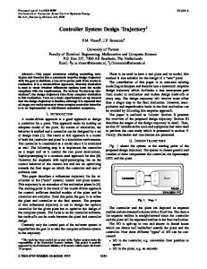
management needs, proper uncertainty definitions in the individual trajectories provide quantified airspace entry and exit times, which are the key parameters for effectively balancing demand and capacity for regulated air sectors. The rest of the paper follows: Section 2 describes the mathematical model of trajectory computation infrastructure. Problem definition of uncertainty quantification process is explained in Section 3 Detailed parametric analysis of error sources for climbing trajectories are explained in Section 4. In order to construct datasets for smarter sampling, aircraft mass and speed intent data from QAR are clustered by the distance of flights in Section 5. An adaptive mass estimation algorithm is utilized in Section 6 to reduce the climb uncertainty in real-time flights. Finally, simulation results are given in Section 7. 2. TRAJECTORY COMPUTATION We have utilized three degrees of freedom equations of motion (point mass) and BADA 4 dataset due to its superior properties to BADA 3. The operational version of the BADA, namely BADA ver. 3, only permits to model aircraft behavior for the normal operation, which is the small subset of the whole flight envelope. However, BADA 4 aims to meet future requirements of the ATM systems in precise calculations reflecting accurate modeling and full-flight envelope of aircraft [29]. Such an advanced representation in BADA 4 allows us to develop effective cost optimization procedures utilizing modal parametric definitions of the aircraft performance. Aircraft Performance Model (APM) illustrated in Figure 1 involves details about the performance parameters of the aircraft including the operational limits. Specifically, the BADA 4 dataset includes Aerodynamic Forces and Configurations Model (AFM) for drag and lift coefficient calculations, Propulsive Forces Model (PFM) for thrust and fuel coefficient calculations, Aircraft Limitation Model (ALM) for identifying geometric, kinematic, dynamic and environmental operation limitations, Operation of Configuration Parameters Model (OPM) to define transition time for both the high-lift devices and landing gear configurations [29]. The interactions between these different models can be found in Table 1.
Figure 1. Trajectory computation model 326
Uzun and Koyuncu / Anadolu Univ. J. of Sci. and Technology A – Appl. Sci. and Eng. 18 (2) – 2017
Table 1. Equations of Trajectory Computation and Aircraft Performance Model x f x, u , , E , t U ,T ,
Aircraft EoM Control and Configuration Inputs
HL , LG , SB E f x, t W f m, E
Earth Model
D f cD ,W , M , E
T f T ,W , M , E
Aircraft Performance Model
F f T ,W , M , E
T f M , E
glim x, x, u, , t 0 f : 0, trans f 1 , 2
Aircraft Limitations Model Operations of Conf. Param. Model
In Table 1, vTAS , , m, ,, h X denote the states of the aircraft and represent the true airspeed, true
airspeed yaw, mass, latitude, longitude and altitude of aircraft respectively, and ,T , U are the control variables that represent the flight path angle, throttle parameter and aerodynamic bank angle respectively. W is the aircraft weight, D is the total drag, T is the total thrust, L is the total lift force and F is the fuel consumption rate. Mc is the ellipsoid radius of curvature in the meridian plane and Nc is in the prime vertical according to the WGS84 earth model. The wind gradients are represented by w1, w2 and w3, which are represented in a proper axes system. The earth model is also described by the vector E , , g , w , where δ is the local pressure ratio, θ is the local temperature ratio, g is the local acceleration of gravity and w is the local wind speed vector. The following 3DOF motion equations are considered sufficient to describe the aircraft dynamics in an air traffic management (ATM) context. vTAS
T D W sin w1 m
(1)
L sin w3 sin w2 cos m v cos
(2)
m F
(3)
vTAS cos sin w2 Nc h cos
(4)
vTAS cos cos w1 M c h
(5)
h vTAS sin
L
(6)
W cos m w3 cos w2 sin
(7)
cos 3. PROBLEM DEFINITON 327
Uzun and Koyuncu / Anadolu Univ. J. of Sci. and Technology A – Appl. Sci. and Eng. 18 (2) – 2017
The problem is given as to quantify the uncertainties in the climbing trajectory through a set consists of mean and standard deviation values. In this study, uncertainties in climb times are in terms of Gaussian error distributions which are expressed as: 1 y f x | , e 2
x 2 2 2
(8)
where is the mean and is the standard deviation. Let Se e , e denotes the set of distribution parameters with Ek : e1 , e2 ,..., eN P : E1 , E2 ,..., EM e11 ,..., e1N , e21 ,..., e2 N ,..., eM 1,...eMN ,
where e is the mean value and e is the standard deviation value of the error set P that consists of M flights. Each element of the distribution Se corresponds the set Ek at flight k. Ek is comprised of climb time errors calculated by trajectory predictor for N aircraft state samples. The samples of the aircraft state distribution are denoted; k : xk1 , xk2 ,..., xk N . Each element xk n |1 n N is a parameter space comprised of aircraft states, which are the aircraft mass m, the climb calibrated airspeed vCAS and the
climb Mach speed Mcmb: xk mk , M cmbk , vCASk . Note that the likelihood for a state hypothesis xk n to n
n
n
n
be included in the sample space k shall be proportional to a specific condition: xk n ~ p xk | yk Let tcmbk and tcmbk represent the climb time calculated by trajectory predictor and real climb time from QAR dataset for the flight k, respectively and are defined as:
tcmb th,lvl th,init tcmb th,lvl th,init , where th ,init and th ,lvl are the times in which the aircraft is at initial reference altitude and cruise level n altitude. Hence, climb time calculated by trajectory predictor for flight k and state sample xk becomes n n n . Note that as a result of the aircraft dynamics described in Section 2, tcmb th ,lvl th ,init k
tcmb f xk f mk , M cmb , vCAS . Let k be the set of calculated climb times of flight k for N samples k k k n
n
n
n
n
of states: 1 2 N k : tcmb , tcmb ,..., tcmb k
k
k
The error set Ek can be rewritten as;
Ek tcmbk k Ek tcmbk tcmb , tcmbk tcmb ,..., tcmbk tcmb . k k k 1
2
N
Thus, 328
Uzun and Koyuncu / Anadolu Univ. J. of Sci. and Technology A – Appl. Sci. and Eng. 18 (2) – 2017
e
1 M N n tcmbk tcmb k MN k 1 n 1
(9)
1 M N 1 M N n n Se t t , tcmbk tcmb e cmbk cmbk k MN MN k 1 n 1 k 1 n 1
2
.
(10)
4. CLIMB UNCERTANITY Main sources of uncertainty in climbing flights are the take-off weight and the speed intent of the aircraft. In this section, the impacts of these sources on climb trajectories will be given through data analytic analysis. The weight has direct impact on climb rate of a flight. In general, the engine thrust is typically set to a fixed rating mode during climb. The flight path angle is then adjusted through the equation 1 to control the speed for a given speed command. Hence, for any power setting, aircraft mass estimation error will lead to a miss estimation of rate of climb. Combining equations 1 and 6, the climb rate can be approximated by the following expression:
dh T D vTAS dvTAS vTAS dw 1 dt mg g dh g dh
1
(11)
Note that from Table 1, it can be seen that thrust T and drag D forces are dependent on aircraft weight. Thus, any error in weight will be reflected as an error in the climb rate through thrust and drag. Additionally, fuel consumption rate F is also going to be impacted by weight errors. The impact of errors in weight on climb gradient can be approximated by observing the derivative of the altitude gradient with respect to the weight. If the wind gradient assumed to be zero, equation 11 can be rearranged as;
dh T D vTAS dvTAS 1 dt mg g dh
1
(12)
The equation for calculating the drag force is D qSCD , where q is the dynamic pressure, S is the wing area and CD is the drag coefficient. In BADA 4 drag polar model, the expression for the drag coefficient is CD k0 k1CL2 k2CL6 , where the coefficients k j are positive real numbers and functions of Mach number M. Hence,
dh T k0 qS k1qSCL2 k2 qSCL6 vTAS dvTAS g dh 1 dt mg mg CL qS
1
(13) (14)
5 1 mg vTAS dvTAS dh T k0 qS k1mg k2 1 dt mg qS qS g dh
(15)
1 4 T k qS k mg vTAS dvTAS 1 dh 0 1 5 k 2 5 dt d mg mg 2 qS qS g dh
(16)
329
Uzun and Koyuncu / Anadolu Univ. J. of Sci. and Technology A – Appl. Sci. and Eng. 18 (2) – 2017
Under the following condition, the climb rate decreases with the increasing aircraft mass:
qS
4
qST k0 qS 2 k1 mg 2 0 6 5k2 mg
k0 qS qST k1 mg 0 2
qS
2
T k0 qS k1 mg
2
1
(17)
The thrust force T is greater than the term k0 qS , which is also called the induced drag, for climbing flights. Thus, the climb rate is increased by decreasing weight and vice versa. If the estimated aircraft mass is higher than the actual one, the actual climb profile will be steeper compared to predicted trajectory. The impact of aircraft take-off weight error on climb trajectory is exerted through a parametric analysis. Although aircraft weight is an essential parameter for predicting climb trajectories, it is not available to ground trajectory predictors as it is a classified information for airlines. In EUROCONTROL’s trajectory prediction tool SAAM, the initial weight of the aircraft is taken as maximum take-off weight. In climb phase of the flight, speed intent refers to a CAS/Mach regime. Typical CAS/Mach climb is characterized by a first stage in which the aircraft climbs at a given constant CAS. The second stage is flown at a given constant Mach number, which also corresponds the cruise speed. Most flights employ CAS/Mach climb regime due to its simplicity of being flown and monitored. The rationale behind this speed configuration relies on the compressibility of air. In the troposphere, true airspeed increases with increasing altitude if calibrated speed is constant. It decreases if Mach number is maintained. In the stratosphere, this dynamic is not the same: True airspeed still grows with altitude, but it does not vary when Mach number remains constant. In order to maintain the target CAS or Mach, pilot or FMC adjusts flight path angle. It is the only remaining control input because the throttle is already fixed to a power regime. Equation 1 can be discretized utilizing Euler’s method:
Tk Dk g sin f k w (18) mk where vk 1 denotes the reference true airspeed to be maintained and X k stands for the states at time step k. vk 1 vk
sin f k w 0
d d 1 dvk 1 dvtgt g
(19)
Equation 19 reveals that as the target speed vtgt increases, the flight path angle should be decreased in order to maintain a constant vCAS or Mach number. Table 2 shows an example parameter list of Airbus A320 aircraft with respect to the speed intent. As the target speed values in CAS/Mach schedules increase, the aircraft has to consume more time to climb to the reference altitude level. Moreover, the traveled distance to top of climb point is longer at higher speed profiles because of reduced rates of climb. 330
Uzun and Koyuncu / Anadolu Univ. J. of Sci. and Technology A – Appl. Sci. and Eng. 18 (2) – 2017
Table 2. Climb parameter of Airbus A320 aircraft to FL 330 [30] Fuel (kg)
Time to Climb (min)
Distance (nm)
CAS/Mach
Rate at TOC (ft/min)
1757
22,4
150
308 / .765
584
1838
23,1
159
321 / .779
566
1897
23,7
165
333 / .783
550
1980
24,7
175
340 / .791
506
2044
25,6
183
340 / .797
461
2080
26,1
187
340 / .800
439
In this work, initial altitude for prediction and calculation of climb times is selected as 10,000 feet due to two main reasons: Trajectories below 10,000 feet are comprised of varying speed and altitude schedules, which come from different Standard Instrument Departures (SIDs). Additionally, these flights may be exposed to instantaneous restrictions or air traffic controller interventions. These kinds of events are unknown and complicated to be modeled accurately. The second reason is to stay in a safe zone, where it is certain that the aircraft is climbing at a constant CAS. Figure 2 depicts the climb trajectories from 10,000 feet to cruise altitudes. The track data is taken from Boeing 737-800 QAR dataset of 1300 flights. As can be seen in this figure, the spectrum of both cruise flight level and climb times are wide. Cruise altitudes vary from 25,000 feet to 41,000 feet while climb times from to these altitudes change from 800 to 1500 seconds. In order to explain that climb time variance is still large enough to evaluate it as uncertainty even for the same cruise flight levels, Figure 3 demonstrates the flights in which the aircraft climbs up to 35,000 feet.
331
Uzun and Koyuncu / Anadolu Univ. J. of Sci. and Technology A – Appl. Sci. and Eng. 18 (2) – 2017
Figure 2. Climb profiles of 1300 Boeing 738 flights, from 10,000 feet to cruise altitudes
Figure 3. Climb profiles from 10,000 feet to 35,000 feet
332
Uzun and Koyuncu / Anadolu Univ. J. of Sci. and Technology A – Appl. Sci. and Eng. 18 (2) – 2017
In this work, we focus on uncertainties over three aircraft states: The aircraft take-off mass, the calibrated airspeed and Mach number in which the aircraft performs CAS/Mach climb. Figure 4 demonstrates the initial take-off mass values of all 1300 flights as a normal distribution, which is defined as: 1 y f x | , e 2
x 2 2 2
(20)
with mean value of 63,253 kg and standard deviation value of 4548 kg. Note that SAAM calculates trajectories by assuming the aircraft is taken off with its maximum take-off weight, while CTAS uses %90 of this value. In Boeing 738 case, the maximum take-off mass is 79,019 kg [31]. The difference between these reference values and the data represented in Figure 4 emphasizes that weight is an essential source of uncertainty.
Figure 4. Take-off mass normal distribution with 63.253 and 4.548 Climb Mach distribution is depicted in Figure 5. These values also represent cruise Mach speed as the Mach climb stage is followed by cruising at the level-off altitude with the same speed. Generally, B738 aircraft cruise at Mach number between 0.76 and 0.82 [31]. As a result, it can be seen that most flight are accumulated on this interval. Moreover, for typical commercial flights, cruise Mach speed is in interval (0,1). Thus, the distribution can be expressed as a beta distribution, which is defined as; y f x | a, b
1 b 1 x a 1 1 x I0,1 x B a, b
(21)
where B(.) is the Beta function. The indicator function I0,1 x ensures that only values of x in range (0,1) have nonzero probability. Distribution parameters are calculated as a 103.98 and b 30.45 . Note that there exist nearly 400 flights in dataset, where the climb Mach number is less than 0.76. The common trajectory prediction tools acquire the speed schedule for an aircraft through BADA Airline Preferences Files [32]. Generic BADA model accepts preferred climb Mach number for Boeing 738 aircraft as 0.78. Although it can be seen in Figure 5 that 0.78 is the approximately most probable speed profile, especially flights flown between 0.65 and 0.70 Mach numbers would result in much higher rate of climbs, thus less amount of climb times.
333
Uzun and Koyuncu / Anadolu Univ. J. of Sci. and Technology A – Appl. Sci. and Eng. 18 (2) – 2017
Figure 5. Climb Mach beta distribution with a = 103.98 and b = 30.45 The probability density function for the third state, climb calibrated airspeed vCAS is represented in Figure 6 as a normal distribution. The mean and standard deviation are calculated as 291.75 and 14.70 kts respectively. The reference climb CAS for B738 aircraft is exerted as 300 kts in BADA Airline Preferences Model. It can be inferred in the Figure 6, this value has the highest likelihood of being sampled in the dataset. However, even errors in range (-20,20) kts may cause prediction errors, as illustrated in Table 2. In this section, data driven model for quantification of uncertainties in climbing flights is acquired through data analytic analysis of QAR dataset. The model focuses on the three main performance parameters, in which the climb time uncertainty is most impacted: The initial take-off mass, the climb calibrated airspeed and the section climb Mach number are fit to proper probability density functions utilizing QAR data. The following sections proposes a clustering process to generate smarter sampling spaces.
Figure 6. Climb CAS normal distribution with 291.75 and 14.70 kts 334
Uzun and Koyuncu / Anadolu Univ. J. of Sci. and Technology A – Appl. Sci. and Eng. 18 (2) – 2017
5. CLIMB PARAMETER – FLIGHT RANGE REGRESSION In this part of the work, a regression between flight range and aircraft take-off mass and climb speed schedule is established via QAR dataset. The reason behind the selection of flight distance as the key parameter relies on Cost Index, which is a feature of the flight management computer and utilized by airlines to reduce the trip cost. Cost Index concept aims to achieve minimum trip cost by means of tradeoff between operating costs per hour and incremental fuel burn. The total cost of a specific trip can be expressed as the sum of fixed and variable costs: J cF m cT t cC
(22)
where cF is the cost of fuel per kg, cT is the time-related cost per minute of flight, m is the total amount of fuel consumed during trip, t is the trip time and cC is the time-invariant fixed costs. In order to minimize the total cost J, the variable cost J v cF m cT t is minimized. Let cF be a fixed value and c c redefine J J v / cF m T t with T CI . For a pre-defined distance S , the cost function can be cF cF rewritten as 1 CI J (23) SR V where SR S / m is the specific range under the weight, altitude and other conditions. Specific range represents the horizontal distance that an aircraft can fly per unit of burnt fuel. It can be reformulated as; dr vTAS SR f W , M , E . (24) dm F
V aM wavg is the ground speed to travel S length distance with a and wavg are the speed of sound and average the wind speed along the aircraft direction, respectively. Hence, the optimization problem becomes to find a proper speed profile that regulates time and fuel related costs, for a given travel distance.
335
Uzun and Koyuncu / Anadolu Univ. J. of Sci. and Technology A – Appl. Sci. and Eng. 18 (2) – 2017
In view of this information, the correlation between travel distance and take-off weight, climb Mach number and climb calibrated airspeed is going to be investigated. Figure 7 depicts the scatter plot of the sets S rk ℝ : r 0 and m mk xk with m , which represent the flight distance and the take-off mass. As can be seen in this figure, there exist a linear correlation between the flight distance and the initial weight. Hence, this relation can be modeled using linear regression, which asserts that the response is a linear function of the inputs [33]: D
y x wT x wj x j
(25)
j 1
where w T x represents the inner or scalar product between the input vector x and the model’s weight vector w, and is the residual error between the linear prediction and the true response. It is assumed that has a normal distribution with ~ N , , where is the expected value and 2 is the variance. This expression can be expanded in the following form: p y | x, N y | x , x
w, The equation can be reformulated for the sampling space of aircraft mass m :
p mk | rk p mk | rk , rk
(26)
In this case, the linear equation is calculated as;
y 4.751x 57.442
(27)
where ~ N 0,3881.7 is a Gaussian noise with 0 and 3881.7 kg. Climb Mach number set is defined as M M cmb xk with M 0.55,0.82 and M . Figure 8 k
depicts climb Mach number M versus flight distance S plot.
Figure 7. The scatter plot of aircraft mass versus travel distance 336
Uzun and Koyuncu / Anadolu Univ. J. of Sci. and Technology A – Appl. Sci. and Eng. 18 (2) – 2017
Figure 8. The scatter plot of climb Mach versus travel distance As already illustrated in Figure 5, most flights in the dataset have climb Mach number M cmbk 0.76,0.82 . However, speed schedules for short range flights in which the aircraft climb at constant Mach number between 0.6 and 0.82 are major sources of uncertainty because the climb gradient is highly effected. A first-order system response approach can be used for Mach number and flight range, depicted in Figure 8: x y x c 1 e
(28)
where ℝ is a constant number and is a Gaussian distribution with zero mean. The resulted equation is obtained as: x y x 0.8 1 e 150
(29)
with ~ N 0,0.09 . Scatter plot of climb CAS with respect to range is depicted in Figure 9. Similar to the weight – flight distance distribution, calibrated airspeed – flight distance distribution is also linear and bounded. However, it can be seen that climb CAS does not vary much with increasing flight distance. Hence, the resulted linear equation becomes y x with ~ N 291.2, 31.65 .
337
Uzun and Koyuncu / Anadolu Univ. J. of Sci. and Technology A – Appl. Sci. and Eng. 18 (2) – 2017
Figure 9. The scatter plot of climb CAS versus travel distance 6. Adaptive Weight Estimation in Real-Time Climbs This section utilizes the adaptive take-off weight estimation method proposed in [20]. The idea in the adaptive method is to use observed aircraft data to improve climb trajectory predictions by dynamically adjusting the modeled aircraft weight. The algorithm compares the energy rate computed using track data and predicted one obtained via prediction tool. The weight is then estimated such that modeled energy rate converges to observed energy rate. Energy rate is defined as the rate of change of the kinetic and potential energy of an aircraft. The derivation of energy rate expression is the combination of pointmass equations of motion 1 and 6:
T D vTAS mg
dv dh mvTAS TAS dt dt
(30)
Equation 30 can be re-expressed as: 1 dvTAS 1 d w cos w T D sin g dt g dt W
(31)
where w is the horizontal wind vector and w is the wind direction. For simplification, the term vTAS is rearranged as: dvTAS dvTAS dh . dt dh dt
During a fixed CAS/Mach climb regime, dvTAS / dh can be assumed as constant in the constant CAS stage. Hence, the algorithm is effective only in this phase of the climb, which is generally between 15,000 and 25,000 feet. Note that the nominal flight path angle is generally around 3 degrees. The 338
Uzun and Koyuncu / Anadolu Univ. J. of Sci. and Technology A – Appl. Sci. and Eng. 18 (2) – 2017
small angle approximation can be applied such that sin . Equation 31 can be partitioned into observed energy rate Eobs and predicted energy rate E pred , which are defined as: 1 dvTAS dh 1 dh 1 d w cos w g dt dt vTAS dt g dt T D W
Eobs
(32)
E pred
(33)
Observed energy rate is comprised of states that can be acquired through position data and wind state, which is provided by weather forecasts. Predicted energy rate incurs modeled thrust and drag forces. The weight is estimated when a state is observed through radar track; calculated using BADA aircraft performance model when the observation is not available. The weight estimation problem is formulated as finding a proper weight that minimizes the difference between observation and predicted energy rates at each iteration step:
h 1 dvTAS 1 d w cos w Tt Dt ht t g dh t vTASt g dt Wt 1 t Et x * min Δ𝐸̇ 𝑡(𝑥)
Et Eobst E predt W∈R
(34) (35)
Although the weight that minimizes energy rate difference can be found in a single iteration in Equation 34, future estimations may not be successive due to noises and outliers in track data. In order to overcome the issue and increase the adaptation speed, a sensitivity parameter t is employed. Equation 34 is rewritten such that; 1 E Wt Wt 1 Tt Dt
1
(36)
The sensitivity parameter is then multiplied by the energy rate difference, which is comprised of noise sources: 1 E Wt t Tt Dt Wt 1
1
(37)
The sensitivity parameter is adjusted using the past energy rate differences and the design logic is formulated in the equation below:
Et Eavg 3 max 0.205, t 1 0.05 if t Eavg 0.005 o.w.
(38)
5
where Eavg
E
t j
n 1
5
.
(39)
339
Uzun and Koyuncu / Anadolu Univ. J. of Sci. and Technology A – Appl. Sci. and Eng. 18 (2) – 2017
7. SIMULATION RESULTS In this section, simulation results are illustrated. The climb trajectories are predicted and then climb
times are calculated for given sets of performance parameters xk mk , M cmbk , vCASk
at each flight k.
Simulations are composed of three parts: In the first part, climb parameters are directly sampled from the QAR dataset. The second part constructs smarter sample spaces considering the range of the flight. Weight estimation utilizing observed track data is applied in the third part in order to show that in realtime flights the climb time uncertainty can shrink with the help of the proposed method. Note that the sample spaces for mk are consist of initial take-off weights. However, the climb times from 10,000 feet to cruise altitudes are considered in this paper. Hence, the mass of aircraft at 10,000 feet should also be estimated. In order to overcome this issue, only flights from SAW (Istanbul Sabiha Gokcen) airport to FRA (Frankfurt) airport with the same SID procedure are used. Climb times to 10,000 feet for these 100 trajectories construct a Gaussian distribution with mean value of 432.8 seconds and standard deviation value of 52.3 seconds. At each prediction, climb time to 10,000 feet is sampled from this distribution. Then, the fuel consumption for this segment of the flight is estimated assuming the aircraft is mandated to fly at its nominal climb speeds, which are calculated through BADA models. The sample spaces in the first scenario are constructed using the data represented in Figures 4,5 and 6. The climb parameters take-off mass and climb speed schedule are directly sampled from these sets. In the second simulation, the regression formulations obtained in Section 5 are used. The probability density functions for take-off mass and climb Mach number are calculated with respect to the range the aircraft is planned to fly. Figure 10 demonstrates an example set of probability density functions for aircraft mass with varying flight ranges. As expected, the mean value for each distribution increases with the flight range. In a similar way, climb Mach probability distributions are constructed and depicted in Figure 11. Climb CAS is sampled from the distribution depicted in Figure 6 because of the lack of dependency on the flight range. Note that standard deviations for each distribution are not the same. This is due to a better representation of the real dataset.
Figure 10. Example probability density functions for take-off mass with varying range
340
Uzun and Koyuncu / Anadolu Univ. J. of Sci. and Technology A – Appl. Sci. and Eng. 18 (2) – 2017
Figure 11. Example probability density functions for climb Mach number with varying range Finally, adaptive algorithm is used to simulate real-time flights with weight estimation. QAR data is used as track data in order to generate the simulation. In each prediction, the weight of the aircraft is updated with real data by minimizing the difference between observed and modeled energy rates. Figure 12 represents the resulted probability density functions of three main simulations; direct sampling, regression and adaptive weight scenarios. Selecting climb parameters directly from the sample spaces from QAR data results in a climb time distribution with mean and standard deviation values of -79.11 and 156.45 seconds. Incorporating the relationship between the climb parameters and the flight range, the mean value of climb times is reduced to 23.88 seconds. Standard deviation in the second simulation is 147.65 seconds, which is in fact very close to the standard deviation in the first scenario. The reason behind this result might be due to sampling climb CAS directly, as the same way in the first simulation. The uncertainty in climb time is shrank with using the adaptive weight method. Calculated mean and standard deviation values are 7.01 and 61.87 seconds. It is an expected result as the estimated aircraft mass converges to the actual value, which is the aim of the adaptive algorithm. Additionally, observed track data helps to have an initial estimation of the speed intent since it includes ground speed data.
Figure 12. Resulted probability density functions for the three simulations: Direct sampling, regression and adaptive weight 341
Uzun and Koyuncu / Anadolu Univ. J. of Sci. and Technology A – Appl. Sci. and Eng. 18 (2) – 2017
Figure 13 compares root-mean-square values of the direct sampling, regression and adaptive weight simulations. The error for pre-flight prediction is first reduced using the impact of flight range on aircraft take-off mass and climb Mach. In real-time flights, parameter estimation methods such as adaptive weight estimation, provide more effective uncertainty reduction.
Figure 13. Root-mean-square of the three simulations 8. CONCLUSION In this work, we have investigated the uncertainty sources in climb trajectories and quantified the major sources trough probabilistic definitions. Three major sources of climb uncertainty have been considered; aircraft mass, climb CAS and climb Mach. In our analysis, we have analyzed QAR data of 1,300 Boeing 737-800 aircraft to generate a proper sample set to investigate climb trajectory parameters. In order to predict the climb times to cruise altitudes before the detailed flight plan is available, two different approaches were applied. At first, the climb parameters are directly sampled from the sample spaces constructed by QAR data. In the second method, smarter sample spaces are generated by incorporating the relationship between the climb parameters and the flight distance. A linear regression between the initial take-off mass and the range has been applied, and first order system approach has been applied to climb Mach – flight range data to obtain the analytical expression for the climb Mach number. It has been observed that climb CAS does not vary much with the increasing range. In the second approach, climb CAS has directly sampled again from the same space that was used in the first simulation. Finally, it has been shown that quantified uncertainties on climb trajectory parameters can be effectively estimated through estimated parametric definitions and error factor over these parameters can be effectively reduced. Through the simulations, the impact of reducing the uncertainty in aircraft mass on climb time was illustrated. The future work for this study will be to extend this uncertainty quantification to the en-route phase of the flight as well. The following effort will be to develop adaptive uncertainty reduction and recovery procedures including the wind.
342
Uzun and Koyuncu / Anadolu Univ. J. of Sci. and Technology A – Appl. Sci. and Eng. 18 (2) – 2017
ACKNOWLEDGMENTS The author(s) disclosed receipt of the following financial support for the research, authorship, and/or publication of this article: This work was supported, in part, by Combining Probable Trajectories (COPTRA) project, granted by Horizon 2020 Research and Innovation program. REFERENCES [1] Single European Sky ATM Research (SESAR) Consortium. The ATM target concept (D3). 2007. [2] Federal Aviation Administration, Office of Aviation Policy and Plans. FAA aerospace forecast: fiscal years 2012-2032,”, March 2012. [3] ICAO, Trajectory Based Operations Concept Document (TBOCD), air traffic management requirements and performance panel (ATMRPP), ATMRPP-WG/28-WP/652, 17 February 2015. [4] Green MS, Mondoloni S, Paglione M, Swierstra S, Irvine R, Garcia-Avello C. White Paper, Common methodology and resources for the validation and improvement of trajectory prediction capabilities, 2006. [5] Eurocontrol Experimental Centre, ADAPT2: Aircraft data aiming at predicting the trajectory, December 2009 [6] Coppenbarger, RA. Climb trajectory prediction enhancement using airline flight-planning information. AIAA-99-4147; 1999. [7] McNally D. and Thipphavong D. Automated separation assurance in the presence of uncertainty. In: 26th International Congress of the Aeronautical Sciences;14-19 September 2008; Anchorage, Alaska, USA. [8] Thipphavong, D. Analysis of a multi-trajectory conflict detection algorithm for climbing flights. In: 9th AIAA Aviation Technology Integration and Operations Conference; 21-23 September 2009; Hilton Head, South Carolina. [9] Casado E, Goodchild C, Vilaplana. M. Sensitivity of trajectory prediction accuracy to aircraft performance uncertainty. In: AIAA Infotech at Aerospace Conference, 19-22 August 2013, Boston Massachusetts, USA. 7 [10] Margellos K, Lygeros J. Toward 4d trajectory management in air traffic control: a study based on monte carlo simulation and reachability analysis. IEEE Transactions on Control Systems Technology; Vol. 21, no. 5, September 2013. [11] Liu W, Hwang I. Probabilistic trajectory prediction and conflict detection for air traffic control. Journal of Guidance, Control and Dynamics; Vol. 34, No. 6, December 2011. [12] Knorr D and Walter L. Trajectory uncertainty and the impact on sector complexity and workload. In: SESAR Innovation Days, 29 November – 1 December 2011; Toulouse, France. [13] Kim J, Tandale M, Menon PK. Air-traffic uncertainty models for queuing analysis. In: 9th AIAA Aviation Technology, Integration and Operations Conference; 21-23 September 2009; Hilton Head, South Carolina. 343
Uzun and Koyuncu / Anadolu Univ. J. of Sci. and Technology A – Appl. Sci. and Eng. 18 (2) – 2017
[14] Mueller TK, Sorensen JA, Couluris GJ. Strategic aircraft trajectory prediction uncertainty and statistical sector traffic load modeling. In: AIAA Guidance, Navigation and Control Conference; 05-08 August 2002; Monterrey, California, USA. [15] Chan W, Bach R, Walton J. Improving and validating ctas performance models, In: AIAA Guidance, Navigation and Control Conference; 14-17 August 2000; Denver, Colorado, USA. [16] Bronsvoort J, McDonald G, Paglione M, Young MC, Fabian A, Boucquey J, Garcia-Avello C. Demonstration of improved trajectory prediction using future air navigation systems. Air Traffic Control Quarterly, Vol. 21(4), pp. 355-381, 2013. [17] Konyak AM, Doucett S, Safa-Bakhsh R, Gallo E, Parks PC. Improving ground-based trajectory prediction through communication of aircraft intent. In: AIAA Guidance, Navigation and Control Conference, 10-13 August 2009, Chicago, Illinois, USA. [18] Thipphavong D. Reducing aircraft climb trajectory prediction errors with top-of-climb data. In: AIAA Guidance, Navigation and Control Conference; 19-22 August 2013; Boston, Massachusetts, USA. [19]Mondoloni S. and Liang D. Improving trajectory forecasting through adaptive filtering techniques. In: 5th USA/Europe ATM R&D Seminar; 23-27 June 2003; Budapest, Hungary. [20] Schultz CA, Thipphavong D, Erzberger H. Adaptive trajectory prediction algorithm for climbing flights. In: AIAA Guidance, Navigation, and Control Conference; 13-16 August 2012; Minneapolis, Minnesota, USA. [21] Alligier R, Gianazza D, Durand N. Machine learning applied to airspeed prediction during climb. In: 11th USA/Europe ATM R&D Seminar; 23-26 June 2015; Lisbon, Portugal. [22] Alligier R, Gianazza D, Durand N. Machine learning and mass estimation methods for ground based aircraft climb prediction. IEEE Transactions on Intelligent Transportation Systems 2015; 16: 3138-3149. [23] Alligier R, Gianazza D, Durand N. Learning the aircraft mass and thrust to improve the groundbased trajectory prediction of climbing flights. Transportation Research Part C: Emerging Technologies 2013; 36: 45-60. [24] Eurocontrol. Specification for trajectory prediction. 2010. [25] FAA/Eurocontrol Cooperative R&D. Common trajectory prediction-related terminology. Action Plan 16: Common trajectory prediction capability, October 2004. [26] Paglione MM, Ryan FH, Oaks DR, Summerill SJ, Cale LM. Trajectory prediction accuracy report: user request evaluation tool (URET)/ center-TRACON automation system (CTAS). FAA Technical Document, May 1999. [27] Eurocontrol. System for traffic assignment and analysis at a macroscopic level (SAAM) reference manual. July 2016. [28] Mondoloni S. Aircraft trajectory prediction errors: including a summary of error sources and data. FAA/Eurocontrol Action Plan 16, Common Trajectory Prediction Capabilities, July 2006. 344
Uzun and Koyuncu / Anadolu Univ. J. of Sci. and Technology A – Appl. Sci. and Eng. 18 (2) – 2017
[29] Nuic A, Poinsot C, Iagaru M, Gallo E, Navarro FA, Querejeta C. Advanced aircraft performance modeling for ATM: Enhancements to the BADA model. In: 24th Digital Avionics Systems Conference; October 30 – November 3 2004; Washington DC, USA. [30] AIRBUS Group. Getting to grips with the cost index. Issue II - May 1998. [31] Roberson B. (Boeing), Fuel conservation strategies: cost index explained. Boeing Aero, 2007. [32] Eurocontrol. User Manual for the Base of Aircraft Data (BADA) Family 4. EEC TechnicalScientific Report No. --, Apr. 2014. [33] Murphy K. Machine Learning: A Probabilistic Perspective. Cambridge, Massachusetts, USA: The MIT Press, 2012.
345


![Defining and Visualizing DataDriven Personas - WordPress.com [PDF]](https://m.moam.info/img/260x300/defining-and-visualizing-datadriven-personas-wordp_6479c223098a9e47158b45b1.jpg)