SIMD Design for a Ray Tracing Application. Jamie S. .... laid out over a ground plane in Block World. ... considered to be cubes, as a cube has a top and a bottom face. .... 5 the Screen Space is divided up so that each PE is assigned to a.
Data-Parallel Rendering for Virtual Reality A Quantitative Investigation of SIMD Design for a Ray Tracing Application Jamie S. Cullen, David M. W. Powers, Todd E. Rocko� Department of Computer Science, Flinders University, GPO Box 2100, Adelaide, South Australia, 5001. (jcullen, powers, rocko�)@ist. inders.edu.au
Abstract. It will be argued that optimizing cost-e�ectiveness in parallel computer design must be performed in respect of a target application. This paper quantitatively examines the design and implementation of a simple Virtual Reality application for a SIMD architecture. A uniprocessor version was designed, implemented, and analyzed. Parallel implementations were then proposed. The resulting SIMD computations were then simulated on a detailed model which allows parametric variation of the physical characteristics of the computer's subsystems. Hardware cost tradeo�s were measured against performance in simulation. Design choices and results are presented. The paper concludes with an examination of the signi cance of these results and the possibilities for future research.
1 Introduction 1.1 Motivation To perform parallel computation one must devise a suitable subdivision of the problem and an algorithm to coordinate the solution of each subdivided part. The e�cient mapping of algorithms to underlying machine architecture is of great concern to parallel computer designers, as parallel computers are inherently more expensive to build relative to conventional uni-processor systems. As with uni-processor systems, designers identify and attempt to eliminate bottlenecks in parallel computers. This design process demands measuring resource requirements and utilization in respect of the intended applications. The majority of research into parallel computer engineering attempts to address general purpose computation. This paper provides a step in the direction of investigating physical design tradeo�s for parallel computers from an application-oriented perspective.
1.2 Primary Goal This paper examines the relative performance of parallel computer architectures as applied to a speci c application. The application may be regarded as a case
study to examine these issues. The SIMD (Single Instruction-stream/Multiple Data-stream) class of parallel computers was chosen to compare relative performance.
1.3 Why Compare SIMD Architectures? SIMD computer architecture exploits problem regularity to allow making the individual Processing Elements (PEs) as simple as possible, so as to occupy a minimum amount of chip area. That is, a SIMD architecture allows a maximum number of PEs to t into the available chip area [8]. Unfortunately, it is impossible to design a single optimal SIMD architecture as optimality depends on the tradeo�s among a variety of design constraints, including (but not limited to) raw clock speed. The design constraints include some imposed by the target application. The limitation of SIMD computer architecture, relative to more the general MIMD (Multiple Instruction-stream/Multiple Data-stream) paradigm, is that in a SIMD computer all PEs execute in lock-step instructions provided by a single system controller sequencing a shared program. SIMD PEs are not capable of performing independent program-sequencing operations. This characteristic of SIMD PEs limits the set of problems for which a SIMD computer may be appropriate to those not including signi cant local data-dependency in PE program control. On the other hand, on a hardware cost basis, SIMD computers are signi cantly less expensive than their MIMD counterparts. Thus the primary tradeo� to consider in choosing SIMD is a hardware cost advantage versus a loss of e�ciency in executing programs incorporating datadependent branching1. This study used a simulator to explore the e�ects of varying design parameters of the computer architecture. These parameters re ect the logical complexity and clock rates of the computer's subsystems.
1.4 Why Virtual Reality ? Virtual Reality (VR) was selected as it is a computationally intensive application. To generate images at video rates the problem size grows as factors such as image rate, image quality, scene complexity and degree of player interaction are increased. As the demands for more complex VR grow, uni-processor implementations using current VLSI technology are becoming harder to implement e�ciently, and parallel implementations need to be considered. 1
The choice is not made on the basis of programming model, because the programming models are equivalent: \A SIMD machine can emulate a MIMD machine in linear time by executing an interpreter, which interprets each processor's data as instructions. Similarly, A MIMD machine can simulate a SIMD" [6].
1.5 Methodology � A basic uni-processor version of the application was implemented and a quan-
titative timing analysis performed. This analysis allowed the determination the computationally intensive components of the application, and provided a basis and a justi cation of why parallelization techniques might provide a useful throughput increase for this speci c application. � A complete scene rendering implementation was written in a low-level assembly language on a detailed parallel simulator [9]. In the development of this application it has been necessary to extend the functionality of the simulator and to develop a set of general tools for this purpose. � Throughput measurements have been achieved for varying di�erent aspects of the computer architecture with respect to the speci c application.
1.6 Report Outline This paper continues by brie y describing the application being implemented. A set of results is then presented. The report concludes by analyzing these results and proposing future experiments.
2 The Virtual Reality Application 2.1 Overview In any VR application it is necessary to de ne a model in which the `world' is represented (the World Model). A technique for rendering a rst person perspective view in this World Model must also be selected. Implementing a VR application can be a complex task with many alternatives to world modeling and rendering available. It was decided to keep the design as simple as possible to focus on ways to exploit the parallelism in the application. With this in mind a simple `block' structured World Model was decided upon. A speci c variant on Ray Tracing [3] was then selected to generate rst person perspective images of this World Model. 2
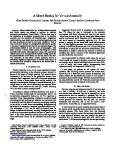
2.2 World Model The term Block World is introduced here to describe the following World Model, where the principal abstraction is the Block.3 The left hand side of Fig. 2 shows from an aerial perspective how blocks are laid out over a ground plane in Block World. The World Model being examined is essentially a nite two dimensional grid in which one block may be placed in only one grid square. A block, as depicted in Fig. 1, has 4 faces. Blocks are not considered to be cubes, as a cube has a top and a bottom face. 2 3
For examples of polygon structured world models and other techniques see [2]. World Models using this general idea are not new. See [7] for similar techniques.
Fig. 1. A basic Block in Block World
Fig. 2. (left) An example world and (right) associated rst-person perspective view
All blocks have the same xed height and dimensions, but may take on various head-on appearances. To do this a texture map (a pixmap) is associated with each block in the world. For example, a face of a block may be given the appearance of a solid stone wall by using a photograph or arti cially generated picture of a stone wall. The name of the texture which is assigned to a block is called the texture attribute of the block. It is possible to de ne other attributes, such as di�erent block shapes, re ective qualities etc. However, only texture is considered in this model.
2.3 Scene Rendering The right hand side of Fig. 2 shows a rendered scene from the uni-processor implementation. The left hand side of the gure shows the Block World from a aerial perspective. The diamond shape represents a person in that world (a Player) and the arrow extending from the diamond represents the direction the
Player is facing. The image to the right of the aerial view represents a rst person perspective view of what that Player in the gure can see from their Point of View (POV). To render this rst-person perspective view in Block World a variant on the ray tracing method was used. In this variant, special e�ects such as di�use, re ected, ambient light etc. are ignored. In all cases, the casting of a ray will stop when it strikes a Block. This is usually known as rst-generation ray tracing [3]. Fundamentally, the idea is to cast a ray into the World Model for every vertical column of the screen, and scale all visible objects (blocks) struck in the ray cast proportional to their distance from the Player.
3 A Model for Parallel Computation 3.1 Overview
The model for SIMD computation used in this research is represented in Fig. 3 [8]. The system controller generates a system clock which regulates all elements of the system. It also sequences and broadcasts instructions via a global instruction broadcast network to an array of PE building blocks. A single PE building block is depicted in Fig. 4. SYSTEM CONTROLLER SYS_CLK
GLOBAL INSTRUCTION BROADCAST NETWORK
DATA INPUT-OUTPUT NETWORK
E
P G D BL CK O L B
E
P G D BL CK O L B
• • •
SYSTEM DATA MEMORY
E
P G D BL CK O L B
INTER-PE COMMUNICATION NETWORK
RESPONSE NETWORK
Fig. 3. Generic SIMD computer (from [8]) The model incorporates two novel abstractions: � values and stepcounts [8]. A � value is associated with each multi-chip subsystem, while a stepcount parameter is associated with each logical operation.
From Global Instruction Broadcast Network SYS_CLK
Local Clocks
Local Controller
Local Instruction Broadcast Network
PE 0
PE 1
PE K−1
Pin Access
Local External Memory Array
PE Chip To Inter−Chip Communication Networks
Fig. 4. PE Building Block (from [8]) A � value expresses the speed of signalling through the wires used to connect chips within the subsystem. The � value is a function of the technology used to implement the subsystem and the topology of its inter-chip wires. A subsystem's � value is a number expressing the factor by which the subsystem's clock rate is lower than the rate of the clock regulating the PEs. This model is based on the assumption that the PE, integrated entirely within a single VLSI component, performs calculations at the highest rate allowed by the VLSI implementation technique used to construct the computer. The model provides one � value per multi-chip subsystem: � SYS CLK - The clock regulating the global instruction broadcast network and the system controller (PE CLK runs �b faster than SYS CLK). � LEM CLK - Local External Memory (LEM) subsystem (�lem ). � COM CLK - Inter PE communication subsystem (�comm ). � IO CLK - System data memory subsystem (�in ). � RSP CLK - Response subsystem (�rsp ). A �-set is an ordered tuple f�b :�rsp :�in :�comm :�lem g that expresses the elec-
trical characteristics of the computer's multi-chip subsystems. Each logical operation performable by a subsystem of a SIMD computer is expressed as machine instruction in the model. A list of instructions is given in Table 14 . Each operation is performed by a speci c subsystem: The PE carries out calculation, LEM performs stores to local memory, the inter-PE communication subsystem transports intermediate results among PEs, and so forth. A stepcount is the number of cycles of the subsystem's clock needed to perform a given operation. The stepcount expresses the ratio between the inherent complexity of a given operation and the subsystem's circuit complexity. For a circuit of given complexity, the more complex the operation the larger the stepcount. For example, a 16-bit PE would take 2 clock cycles to add a pair of 32-bit operands. Another example is that local memory access pins on the PE module may be time-shared. LEM operation stepcounts are proportional to the degree of timesharing.
Table 1. Generic Instructions for a SIMD Computer
Instruction Class ALU Instructions
Instructions pass, and, or, nor, not, add, sub, mult, lshift, rshift Context Management Instructions lc push ge, lc push gt, lc push eq, lc push ne, lc push le, lc push lt Local External Memory Instructions load, store Inter-PE Communication (for a Linear Array) ldn0, lup0 System Data Memory Instructions io ld, io st Literal literal Response Network Instructions respond
The �-value and stepcount abstractions combine to allow a wide variety of SIMD computer variants to be instantiated within the model.
3.2 Guidelines for SIMD-ability The e�ciency of a parallel computer depends on the mapping of algorithm to architecture [10]. In other words, success of parallel computation depends on how the problem is partitioned, how the individual partitions are mapped to PEs, and how the PEs are coordinated. The resulting ratio of intra-PE calculation to inter-PE communication determines the appropriateness of the parallel implementation of a problem. In general, an algorithm with a high degree of conditional branching does not map well onto any SIMD computer. This is because all the PEs in a SIMD 4
Note that although the model provides for several inter-PE communication topologies, only those for a linear array are used in this study.
processor operate in lock-step and they \must all follow every code branch" [2]. The application chosen for this study is amenable to SIMD implementation.
4 Parallel Implementation and Scalability 4.1 Overview
In a ray tracing or a VR application, the spatial arrangement of the World Model is sometimes referred to as the World Space. Likewise, the spatial arrangement of the rendered scene may be referred to as the Scene Space. Approaches to parallelization of scene rendering techniques usually consist of dividing the Scene Space and/or the World Space up in some way. Typically, each subdivided part may then be assigned to separate PEs for computation. If an implementation of scene rendering is considered using ray tracing and related techniques then there already exist several parallel algorithms to do this [1]. However, many of the implementations surveyed rely heavily on nonsystolic inter-PE communication 5 and hence are not suitable for a simple SIMD architecture. Many of these algorithms also require that the processors are executing instructions in a non lock-step (MIMD) fashion for e�cient execution.
4.2 The Basic Parallel Algorithm
The technique that was actually implemented takes advantage of the fact that the computation of a screen column in the Renderer is independent of all other screen columns. More speci cally, since only rst generation rays are being traced, every ray traced in a rendered scene is independent of every other ray, and may be calculated in parallel. This leads to the next observation, which is that each texture scaling operation is also independent of one another and may also be performed in parallel. In Fig. 5 the Screen Space is divided up so that each PE is assigned to a vertical column of the screen. For example, if a 2048x1024 pixel image is to be generated, then 2048 PEs are needed - one for each vertical screen column. As the columns are completely independent of one another inter-PE communication does not need to take place. This implies that a SIMD Linear Array would be an appropriate architecture for the algorithm to be implemented on.6 To render a scene on a SIMD linear array using the above ideas, it was decided to render a scene in the following four stages: � The rst stage initializes the PEs and transfers all the data7, which the PE needs to perform its computation, from global system memory to the PE's 5 6
A good example of this can be found in hypercube implementations [4, 5]. Note the communication network is usually one of the most expensive hardware costs of a parallel machine. If the application only uses minimal communication then it is obviously advantageous cost-wise to implement a simple communication topology. 7 In this initial implementation each PE is provided which a complete copy of the World Model.
local memory. If many images are to be rendered as is the case in VR, this stage becomes the initialization stage for the overall computation, and is not repeated for each image. � The second stage, as shown in Fig. 6 does the ray tracing and stores results in in local PE memory. Note that it is not necessary to export these results to global system memory as the same PE is used in the next stage to draw the part of the block that was just found in the ray trace. � The third stage, as shown in Fig. 7 does all the texture scaling in a single pass. � The fourth stage writes the results back to global system memory. Stages two through till four may be repeated with di�erent starting values to render successive images. Pseudo code for stages two and three is outlined in Fig. 6 and Fig. 7.
Fig. 5. (left) Viewpoint in World Model (right) Division of image among the PEs
for screen column in 1 to
number of PEs init ray; for distance in 1 to max distance do strike an object record position and object struck; HALT this PE;
if
in parallel do
then
end;
Fig. 6. Ray Tracing Parallel Algorithm
for
in
to
in parallel
screen column 1 number of PEs start at centre of texture; for height in 1 to (maximum texture height)/2 do draw more of texture; finished drawing HALT this PE;
if
then
end;
Fig. 7. Texture Scaling Parallel Algorithm 4.3 Parallel Implementation Details The simulation tool used is a detailed parallel simulator called Basis which uses the above model of SIMD computation [8]. In Basis, algorithms are implemented in a low-level assembly language for a generic SIMD architecture. The generic assembly language program is compiled (via the assembler Basc) with settings for a speci c architecture, then run through the parallel simulator. Parallel machinespeci c information such as number of clock cycles for speci c instructions in the instruction set, local memory size, number of PEs etc., are all con gurable by the programmer. This is the rst time a moderately complex application has been coded using Basc and Basis. To test the correctness of the simulator run, utilities were implemented to convert the results stored in the parallel simulator's system memory into an image format, which is displayable by a uni-processor machine. To quantitatively verify the correctness, the resultant image(s) were compared to images generated by the uni-processor implementation. The uni-processor version was considered to be generating the `correct' solution for the purposes of the experiment.
4.4 Data-Parallel Scalability Let n denote the number of PEs, which also corresponds to the image width in the above algorithm. Let m denote image height, and r the maximum viewing distance from the Player's point of view (this corresponds to longest ray that may be traced in any scene). For the purposes of characterizing the time required by the algorithms used for the various phases of computation on di�erent implementations, it is assumed that r, m and n are of the same order. The case of image widths of w > n columns will be discussed in the next section - this doesn't a�ect the results. Using these values it may be observed that the ray tracing time is directly proportional to r. The texture scaling operation depends on image height. Note that as each column is assigned to a unique PE the computation time is independent of the number of PEs. It merely places a limit on how wide an image may be rendered. The write-back (stage four) is also dependent on image height. From this it may be concluded that rendering a scene may be completed in linear time of order O(r) + O(m).
Varying Image Size on Uniprocessor Implementation 120000 "uni.dat"
100000
Execution Time (ms)
80000
60000
40000
20000
0 128
256
384
512 640 768 896 Image Width (Pixels) (w=h)
1024
1152
1280
Fig. 8. Varying Image Size (w=h=n, r=constant) on Uniprocessor In contrast, the results for the uni-processor implementation in Fig. 8 are also dependent on the number of columns n and thus e�ectively require quadratic rendering time. This is because each texture column must be rendered in a sequential fashion. Each ray must also be cast sequentially, making both computations proportional to the image width. i.e. O(nr) + O(nm) for uni-processor implementation.
4.5 A Critique of the Algorithm The lock step nature of the algorithm has its drawbacks. If many objects are struck close to the Player in the ray tracing stage then instructions will still be broadcast, even though the PE has been halted. This may result in poor subsystem utilization for some data sets. Little can be done about this due to the lock-step nature of SIMD. A MIMD version of the algorithm would most likely reassign the (halted) PEs to compute something else. The computation of the rays is not pipelined in the above example. Pipelined approaches usually work out which rays need to be cast, and assign them to a suitable PE [1]. In this case more than one ray may be sent to a PE for a given image, and the one screen column per PE property of the above algorithm does not hold. Note that the algorithm admits rendering the images in a `piecemeal' fashion. That is, if there are n PEs and an image width w the rendering of the image may be performed in w/n passes if w is an integer multiple of n. The results presented focus exclusively and without loss of generality on the
n=w case. However, the algorithm could be generalised to provide better PE utilisation when n � w, as processor relocation is possible since the core loop of the algorithm can be applied to any column and ray segment. Each of the PEs must contain a complete copy of the world model in order to perform the ray tracing and texture scaling. If extremely large world models are used then a scalability problem may occur in which the cost of adding extra local memory for each PE becomes dominant. The current algorithm has an excellent cost and speed advantage over one which shares data between PEs as inter-PE communication is not necessary.
5 Results and Analysis 5.1 Overview
The following results examine the variation of some architectural and algorithmic constraints for the chosen application and architecture. The intention is to focus on some important aspects of the design, rather than to perform an exhaustive analysis of every parameter in both application and architecture (which is beyond the scope of this paper). A computer operating on 32-bit integers with 16-bit PEs packed 4 to a chip (such as the example of SLAP in [8]) was selected for simulation. The architecture's characteristics were then modi ed from the base con guration to see the e�ects on performance. In the following experiments both image height and width are made equal to the number of processors, i.e. an n�n image is rendered. This is done as an increase in image resolution or size usually corresponds to an increase in both width and height - It makes more sense to vary both parameters from an image rendering point of view, as video images normally have a xed aspect ratio (although this is typically 4:3). Further more, the maximum viewing distance r (another important algorithmic parameter), is kept constant for the presented results (arbitrarily set to a distance of 32 blocks). In this sense, the analysis has been simpli ed by not considering these possible variations in the application. The following graphs give results for varying operation stepcounts for local and system memory instructions. Memory instructions were selected as memory access times typically form an important bottleneck in any computer system design. One set of graphs is used to indicate the linear relationship between overall system clock cycles and number of processors. A second graph is then given using the same data, but demonstrating a di�erent relationship: System clock cycles versus the operation stepcount. The stepcount is varied for a xed number of processors (Arbitrarily chosen as 1280 PEs). The highlighted item in the graphs (indicated by lines and points for the varying PE count graphs) indicates the baseline system. Other points indicate a variation from this baseline system. The emphasis in these results is on varying single hardware parameters one at a time to examine hardware tradeo�s for a speci c application. The scalability of these e�ects is considered with respect to increased image area.
5.2 Variation of System Memory Store Stepcount Varying IO Store stepcount at RHO-set {8:8:8:4:2} "1" "2" "3" "4" "5" "6" "7" "8" "9" "10"
2e+07
System Clock Cycles
1.5e+07
1e+07
5e+06
0 128
256
384
512
640 768 896 Number of PEs
1024
1152
1280
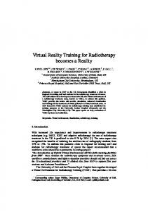
Fig. 9. Varying System Memory Store stepcount over a range of PE counts (w=h=n) The linear relationship between clock cycles and PE count/image width was predicted to show increased slope with increased cycle count for increased IO ST stepcount.8 This is because IO ST is used to write completed images from Local PE memory back to system memory, and the amount of writing necessary depends on the image height h. As the cost in clock cycles of IO ST is increased, an increase in the gradient would be expected since the cost of writing each of the w�h pixels of the image is increased equally. A linear relationship between Total Clock Cycles and IO ST Cycles would thus be expected. Figure 9 shows that this predicted result was achieved, but with one major di�erence: For the rst three values of stepcount the same number of clock cycles was achieved. This relationship is shown more clearly in Fig. 10. This unexpected result may be attributed to the scheduling algorithm the assembler implements. What is happening is that for low stepcount the IO ST instructions are able to be completely interleaved with other instructions, and varying the latency of the instruction has no overall e�ect on computation time (system clock cycles). Once the IO ST instruction stepcount is increased beyond those values the scheduler is 8
The number of processors is assumed to be the same as the width in columns and the height in rows the plots in Fig. 9 and Fig. 11 are thus all linear as a quadratic amount of work is being done by a linear number of processors.
Varying IO Store stepcount at RHO-set {8:8:8:4:2} for image size 1280x1280 2.5e+07 "io_vs_clks.dat" "io_vs_clks.2.dat"
System Clock Cycles
2e+07
1.5e+07
1e+07
5e+06
0 1
2
3
SLAP
5 6 IO Store Stepcount
7
8
9
10
Fig. 10. Varying System Memory Store stepcount for 1280 processors no longer able to completely interleave the instructions and a linear relationship is observed as expected. Note that the linear relationship in Fig. 9 is typical of the computation remembering that the results are graphed for linearly and proportionately increasing image area, and that the e�ect of increasing the image width is countered by the excellent scalability with the tracking number of PEs.
5.3 Variation of System Memory Load Stepcount A similar analysis was performed for varying System Memory Load Stepcount. As the System Memory Load instruction (IO LD) is only used in the initialization stage of the computation to load the world model into local PE memory it is part of a xed overhead only. Increasing this initialization overhead has little e�ect on the overall computation when a large set of scenes is rendered, and has no detrimental e�ects on scalability. No unexpected e�ects (e.g. instruction interleaving) were observed in this case.
5.4 Variation of LEM Load Stepcount In Fig. 11 a similar relationship to that predicted for IO ST was expected. This is because the LOAD instruction is primarily used in the texture scaling stage which is proportional to the image height h (= w = n). Once again, the prediction proved accurate, but with one correction: System clock cycles versus number
Varying LEM Load stepcount at RHO-set {8:8:8:4:2} 2e+07 "1" "2" "3" "4" "5" "6" "7" "8" "9" "10"
System Clock Cycles
1.5e+07
1e+07
5e+06
0 128
256
384
512
640 768 896 Number of PEs
1024
1152
1280
Fig. 11. Varying LEM Load stepcount over a range of PE counts (w=h=n) Varying LEM Load stepcount at RHO-set {8:8:8:4:2} for image size 1280x1280 2.5e+07 "load_vs_clks.dat" "load_vs_clks.2.dat"
System Clock Cycles
2e+07
1.5e+07
1e+07
5e+06
0 1
2
3
SLAP
5 6 LEM Load Stepcount
7
8
9
10
Fig. 12. Varying LEM Load stepcount for 1280 processors
of PEs (equivalent to image width) was graphed for ten values of LOAD stepcount. Ten unique linear relationships were expected with positive gradient for increased stepcount. Only three unique lines were obtained. This result may be attributed to an e�ect known as quantization. Fig. 12 more clearly demonstrates how a new line is only formed when stepcount is increased by a factor of �b /�lem (A factor of 4 in this case). This interrelationship demonstrates how a seemingly unrelated subsystem can have a subtle impact on performance of another. Matching the speeds of subsystems may be seen as desirable in this instance even if (strangely enough) it means cutting costs to make the LEM subsystem slower to match the clock rate of the Global Instruction Broadcast Network. It may be observed that if quantization is occurring then a reduction in complexity of LOAD stepcount (in this case) may or may not make a di�erence.
5.5 Variation of LEM Store Stepcount The local memory storage instruction (STORE) is used predominantly in the texture scaling stage. As this is proportional to image height a similar relationship would be expected to the above predicted ones. Once again results held a few surprises. The expected linear relationship was present, however the variation of stepcount for a xed image size yielded the interesting result that the variation of the stepcount made no di�erence to the overall execution time for a xed image size. What is happening here is a combination of quantization and instruction interleaving. As with LOAD the instruction scheduling of STORE is being regulated by the relationship between the Global Instruction Broadcast and LEM subsystem clocks. However, it is also the case that for low stepcount the STORE instructions may be completely interleaved with other instructions. Whereas LOAD must wait for a result, STORE simply `passes a value down the line'. The reason for the interleaving working with IO ST is similar. The scheduling of LOAD or IO LD instructions is inherently more complex as they are usually phase split into transmit (TX) and receive (RX) pairs. The TX and RX instructions must appear separate from each other at a xed number of instruction slots.9 If other instructions depend on the result of the LOAD (very probably) then these concepts all combined make it di�cult to interleave LOAD instructions as e�ectively as STORE instructions.
6 Conclusions Clearly, the implementation of the application on a SIMD computer gives a linear speedup over the uni-processor version. This is not surprising, although originally there was a question as to whether the overhead between the ray tracing and texture mapping stages of computation might prove signi cant. The 9
This number of slots for phase-split instructions is dependent on the product of �-subsystem and stepcount.
current level of results have shown that the overhead is insigni cant in terms of the scalability and SIMD-ability of the computation. What is interesting about the above results is that they highlight two interesting phenomena: namely quantization and instruction interleaving. Although these e�ects are understood qualitatively, the magnitudes and breakpoints are application dependent and are di�cult to quantify analytically. Knowing in a relative sense how slow a part of the architecture can be made before it makes a di�erence to the overall computation allows a relative importance to be attached to how much should be spent on making it go as fast as possible. It may be the case that due to the above phenomena the extra expenditure for a speed increase in the subsystem may make no signi cant di�erence to the computation. Further analysis of this type will allow an identi cation of the bottlenecks in the system and where money would be best spent to achieve a maximalspeed increase for a speci c application. The answer ultimately depends on the relative costs of the hardware variants.
References 1. J. Arvo and D. Kirk. A survey of ray tracing acceleration techniques. In A. Glassner (editor), An Introduction to Ray Tracing, pages 201{262. Harcourt Brace Jovanovich, 1989. 2. Foley, van Dam et al. Computer Graphics : Principles and Practice. The Systems Programming Series. Addison Wesley, second edition, 1993. 3. A. Glassner. An overview of ray tracing. In A. Glassner (editor), An Introduction to Ray Tracing, pages 201{262. Harcourt Brace Jovanovich, 1989. 4. Goldsmith and Salmon. A ray tracing system for the hypercube. Caltech Concurrent Computing Project Memorandum HM154, California Institute of Technology, 1985. 5. Kobayashi et al. Parallel processing of an object space for image synthesis using ray tracing. The Visual Computer, Volume 3, Number 1, 1987. 6. The Connection Machine. W. D. Hillis. ACM Distinguished Dissertations. The MIT Press, 1987. 7. Larry Myers. Notes on ack3d (animation construction kit). Available via ftp : x2ftp.oulu. :/pub/msdos/programming/ack/. Text document outlining design decisions in 3D construction kit. 8. Todd E. Rocko�. An Analysis of Instruction-Cached SIMD Computer Architecture. Ph.D. thesis, Carnegie Mellon University, 1993. 9. Todd E. Rocko�. A Physical Model of SIMD Computation. Carnegie Mellon University, 2.3 edition, April 1995. 10. Skef Wholey. Automatic Data Mapping for Distributed-Memory Parallel Computers. Ph.D. thesis, Carnegie Mellon University, May 1991.
This article was processed using the LATEX macro package with LLNCS style