DYNAPRO PRO SERIES REAR KIT FOR OE PARKING BRAKE ... Modifications
are necessary to the stock hub/caliper mounting bracket assembly. ... Review the
Wheel Clearance Diagram (Figure 2, page 3) to verify that there is adequate ...
vehicle's hubs (i.e., brackets for a 1996 Subaru hub will not fit a 2002 Subaru hub
).
www.wilwood.com
ASSEMBLY INSTRUCTIONS FOR
DYNAPRO PRO SERIES REAR KIT FOR OE PARKING BRAKE WITH 12.19” DIAMETER VENTED ROTOR 1999 - 2004 SUBARU IMPREZA WRX PART NUMBER GROUP
140-7006 DISC BRAKES SHOULD ONLY BE INSTALLED BY SOMEONE EXPERIENCED AND COMPETENT IN THE INSTALLATION AND MAINTENANCE OF DISC BRAKES
READ ALL WARNINGS WARNING IT IS THE RESPONSIBILITY OF THE PERSON INSTALLING ANY BRAKE COMPONENT OR KIT TO DETERMINE THE SUITABILITY OF THE COMPONENT OR KIT FOR THAT PARTICULAR APPLICATION. IF YOU ARE NOT SURE HOW TO SAFELY USE THIS BRAKE COMPONENT OR KIT, YOU SHOULD NOT INSTALL OR USE IT. DO NOT ASSUME ANYTHING. IMPROPERLY INSTALLED OR MAINTAINED BRAKES ARE DANGEROUS. IF YOU ARE NOT SURE, GET HELP OR RETURN THE PRODUCT. YOU MAY OBTAIN ADDITIONAL INFORMATION AND TECHNICAL SUPPORT BY CALLING WILWOOD AT (805) 388-1188, OR VISIT OUR WEB SITE AT WWW.WILWOOD.COM. USE OF WILWOOD TECHNICAL SUPPORT DOES NOT GUARANTEE PROPER INSTALLATION. YOU, OR THE PERSON WHO DOES THE INSTALLATION MUST KNOW HOW TO PROPERLY USE THIS PRODUCT. IT IS NOT POSSIBLE OVER THE PHONE TO UNDERSTAND OR FORESEE ALL THE ISSUES THAT MIGHT ARISE IN YOUR INSTALLATION. RACING EQUIPMENT AND BRAKES MUST BE MAINTAINED AND SHOULD BE CHECKED REGULARLY FOR FATIGUE, DAMAGE, AND WEAR.
Need Additional Information? Use Your SmartPhone and Jump to Our Technical Tips Section on Our Web Site.
WARNING DO NOT OPERATE ANY VEHICLE ON UNTESTED BRAKES! SEE MINIMUM TEST PROCEDURE WITHIN ALWAYS UTILIZE SAFETY RESTRAINT SYSTEMS AND ALL OTHER AVAILABLE SAFETY EQUIPMENT WHILE OPERATING THE VEHICLE IMPORTANT • READ THE DISCLAIMER OF WARRANTY INCLUDED IN THE KIT
NOTE: Some cleaners may stain or remove the finish on brake system components. Test the cleaner on a hidden portion of the component before general use.
Important Notice - Read This First Before any tear-down or disassembly begins, review the following information: • Modifications are necessary to the stock hub/caliper mounting bracket assembly. We have included a “template” with the instructions, see last page.
• Review the Wheel Clearance Diagram (Figure 2, page 3) to verify that there is adequate clearance with the wheels you will be using with the installation. • Rear brake kits are not supplied with hydraulic lines or fittings and may require the purchase of additional lines or fittings to complete the installation. Wilwood offers an extensive listing of brake lines and fittings on our web site: www.wilwood.com. • Rear brake kits are not supplied with parking brake cables hardware or adapters. Please see the note in the assembly instructions for vendor recommendations to purchase. • Due to OEM production differences and other variations from vehicle to vehicle, the fastener hardware and other components in this kit may not be suitable for a specific application or vehicle. • It is the responsibility of the purchaser and installer of this kit to verify suitability / fitment of all components and ensure all fasteners and hardware achieve complete and proper engagement. Improper or inadequate engagement can lead to component failure.
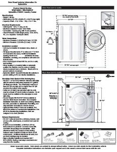
Exploded Assembly Diagram and Parts List 13
NOTE SPECIFIC PARTS MAY VARY FROM DIAGRAM
WARNING INSTALLATION OF THIS KIT SHOULD ONLY BE PERFORMED BY PERSONS EXPERIENCED IN THE INSTALLATION AND PROPER OPERATION OF DISC BRAKE SYSTEMS.
9 STOCK MOUNTING HOLES (2 PLACES)
10
11 12
3 2 8 1 SEE INSET BOX BELOW
NOTE: OPTIONAL DRILLED/SLOTTED ROTOR SHOWN FOR REFERENCE PURPOSES
4
STOCK BACKING PLATE CALIPER BRACKET
7
5
6
CALIPER BRACKET MOUNTING EARS. MATERIAL TO BE REMOVED INDICATED IN BLACK
MODIFIED BACKING PLATE/ CALIPER BRACKET
Figure 1. Typical Installation Configuration, Left Hand Application Shown Page 2
Parts List ITEM NO. 1 2 3 4 4A 5 6 7 8 9 10 11 12 13 Optional
PART NO. 250-6982 240-10190 230-7003 160-9585 160-6924/25 170-10108 240-11240 230-6738 120-9706 230-10025 240-10190 240-1159 150-8946K 180-0054S 220-7010
DESCRIPTION
QTY
Bracket, Caliper Mounting Washer, .391 I.D. x .625 O.D. x .063 Thick Bolt, 3/8-24 x 0.75 Long, Hex Head Rotor, .81” Thk x 12.19” Dia, 8 x 7.78” Bolt Circle Rotor, Drilled and Slotted (one each, left and right) Hat Washer, .265 I.D. x .500 O.D. x .063 Thick Bolt, 1/4-28 x 0.75 Long, 12 Point Caliper, Billet DynaPro Bolt, 3/8-24 x 1.25 Long, Hex Head Washer, .391 I.D. x .625 O.D. x. 063 Thick Shim, .035 thick Pad, BP-10, Axle Set Cottor Pin Braided Stainless Steel Hose Kit (Not Included)
2 4 4 2 2 2 16 16 2 4 4 16 1 2
NOTES: Part Number 230-7011 Rotor Bolt Kit, includes part numbers 230-6738 and 240-11240 Part Number 230-7012 Caliper Bracket Mounting Bolt Kit, includes P/N’s 230-7003 and 240-10190 Part Number 230-11861 Caliper Mounting Bolt Kit, includes P/N’s 230-10025, 240-10190 and 240-1159 Item 4A is an optional item and is included in the (D) kits. Add “-D” to end of part number when ordering
Photographic Tip Important and highly recommended: Take photos of brake system before disassembly and during the disassembly process. In the event, trouble-shooting photos can be life savers. Many vehicles have undocumented variations, photos will make it much simpler for Wilwood to assist you if you have a problem.
General Information and Disassembly Instructions Installation of this kit should ONLY be performed by persons experienced in the installation and proper operation of disc brake systems. Before installation begins, please read the complete procedure thoroughly to familiarize yourself with the process, and double check the following items to ensure a trouble-free installation.
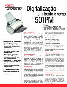
0.37 (9,4) 0.05 (1,3)
INSIDE WHEEL PROFILE (MINIMUM REQUIRED FOR CLEARANCE)
CALIPER
•Make sure this is the correct kit to match the exact make and model year of the vehicle’s hubs (i.e., brackets for a 1996 Subaru hub will not fit a 2002 Subaru hub).
6.57 (166,9) 7.20 (182,9)
•Verify the hat stud pattern in this kit matches the stud pattern of the vehicle’s wheels. WILWOOD ROTOR
•Verify your wheel clearance using Figure 2. •Inspect the package contents against the parts list to ensure that all components and hardware are included.
Disassembly •Disassemble the original equipment rear brakes: Raise the rear wheels off the ground and support the rear suspension according to the vehicle manufacturer’s instructions. Disconnect the caliper brake hose from the brake line at the body. Remove the two bolts that hold the stock caliper to the stock caliper mounting bracket. Remove the caliper, then slide off the stock hat and rotor assembly. Remove the dust shield that is spot welded from the front of the caliper mounting bracket (Wilwood suggests removal by drilling through the center of the spot welds).
Page 3
FACE OF HAT 3.89 (98,9) FACE OF HUB
CENTER LINE OF WHEEL
FACE OF SPINDLE WHEEL STUDS
STOCK WHEEL MOUNTING SURFACE OFFSET .26 HAT THICKNESS
Figure 2. Wheel Clearance Diagram
Disassembly (Continued) and Assembly Instructions Carefully cut out the pattern template (attached to this document). Using the stock bolts, bolt through the caliper mounting holes on the template and attach to the OEM backing plate. Cut away the marked area, using the provided template as a reference guide (leaving some material near the cut line for additional cutting later, if necessary). Mount the new caliper (8) to the caliper mounting bracket (1) using the supplied bolts (9) and three shims (11) placed between the caliper and the bracket. Install caliper (8) and bracket (1) to the modified OEM caliper bracket. Check clearance between caliper ears and OEM caliper bracket ensuring the new caliper ears clear (mounts flush) the OEM bracket. If necessary, file OEM bracket (using template as reference) for clearance between caliper (8) mounting ears and OEM bracket mounting ears. Check for clearance and file more if necessary. Clean up spot welds and related area, then paint modified/exposed metal to prevent rusting. Assembly Instructions (numbers in parenthesis refer to the part list/diagram on the preceding page): CAUTION: All mounting bolts must fully engage insert nuts. Be sure to check that all bolts are either flush or protruding through flanged side of insert nut after shimming.
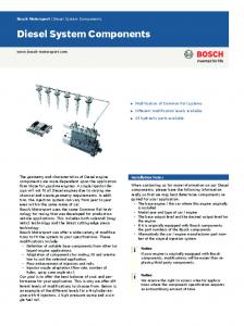
BEGIN BY SLIDING THE 0.032" DIAMETER WIRE THROUGH TWO OF THE HOLES (LEFT) THAT ARE 180° APART. TWIST THE WIRE AS SHOWN (BELOW) USING SAFETY WIRE PLIERS. NOW SLIDE ONE WIRE THROUGH TWO OF THE HOLES (180° APART) AND WRAP THE OTHER WIRE AROUND THE BOLT. TWIST THE WIRES TOGETHER TO FORM A PIGTAIL. SEE DS-386 FOR COMPLETE DETAILS.
Figure 3. Safety Wire Diagram
•Slide bolt (3) through washer (2) from the backside of the modified OEM caliper mounting bracket. Apply red Loctite® 271 to the caliper mounting bracket bolt threads (3) before installation of the caliper mounting bracket (1). Install the caliper mounting bracket (1) with the threaded inserts facing the outside of the vehicle. Finger tighten. Repeat for the lower mounting holes. Torque bolts to 40 ft-lb. •With the larger I.D. side of the rotor (4) facing away from the hat (5), bolt rotor (4) to hat (5) through the back side of the rotor using washers (6) and bolts (7). Using an alternating sequence, apply red Loctite® 271 to the threads and torque bolts to 140 in-lb. For an added measure of security, the bolts may be safety wired using standard 0.032 inch diameter stainless steel safety wire as shown in Figure 3. Please refer to Wilwood’s data sheet DS-386 (available at www.wilwood.com/Pdf/DataSheets/ds386.pdf) for complete safety wire installation instructions. Slide the rotor/hat assembly onto the hub. Install a couple of lug nuts (finger tighten) to keep the rotor/hat assembly in place while continuing with the installation.
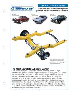
END OF CLINCH NUT
END OF BOLT HEAD OF BOLT
CORRECT END OF BOLT IS FLUSH WITH, OR SLIGHTLY PROTRUDING FROM END OF CLINCH NUT
END OF CLINCH NUT
END OF BOLT
•NOTE: Please reference the caution statement at the beginning of the assembly instructions. Mount the caliper (8) onto the caliper mounting bracket (1) using two bolts (9) and two washers (10). View the rotor (4) through the top of the caliper (8). The rotor (4) should be aligned in the center of the caliper (8). If not, loosen the two bolts (9) and adjust the caliper (8) by using 0.035 inch thick shim washers (11). The shim washers (11) should be placed between the caliper (8) and the caliper mounting bracket (1). Finger tighten and recheck alignment. Add as many shim washers (11) as necessary to achieve the correct alignment. NOTE: The end of the bolt must be flush with or slightly protuding from the head of the clinch nut. See Figure 4. Place spare shims (11) between washer and caliper mounting ear to achieve the proper mounting fastener configuration. Always use the same amount of shims on both the top and bottom caliper mounting bolts (9). Loosen the two bolts (9) and apply red Loctite® 271 to bolt threads (9) and torque to 40 ft-lb. •Position the Wilwood disc brake pads (12) into the caliper (8) and secure with cotter pin (13). Steel backing plate side of brake pad should face the caliper pistons. •NOTE: OEM rubber brake hoses generally cannot be adapted to Wilwood calipers. The caliper inlet fitting is a 1/8-27 NPT. The preferred method is to use steel adapter fittings at the caliper, either straight, 45 or 90 degree and enough steel braided line to allow for full suspension travel and turning radius, lock to lock. Carefully route lines to prevent contact with moving suspension, brake or wheel components. Wilwood hose kits are designed for use in many different vehicle applications and it is the installer's responsibility to properly route and ensure adequate clearance and retention for brake hose components. Wilwood offers a hose kit, P/N 220-7010, which includes hoses, fittings, etc., all in one package for this application.
HEAD OF BOLT
WRONG END OF BOLT IS BELOW END OF CLINCH NUT END OF CLINCH NUT
END OF BOLT
HEAD OF BOLT
WRONG END OF BOLT IS PROTRUDING TOO FAR FROM END OF CLINCH NUT AND MAY INTERFERE WITH MOVING PARTS
Figure 4. Clinch Nut Engagement Diagram
•Specified brake hose kits may not work with all Years, Makes and Models of vehicle that this brake kit is applicable to, due to possible OEM manufacturing changes during a production vehicle's life. It is the installer's responsibility to ensure that all fittings and hoses are the correct size and length, to ensure proper sealing and that they will not be subject to crimping, strain and abrasion from vibration or interference with suspension components, brake rotor or wheel.
Page 4
Assembly Instructions (Continued) •In absence of specific instructions for brake line routing, the installer must use his best professional judgment on correct routing and retention of lines to ensure safe operation. Test vehicle brake system per the 'minimum test' procedure stated within this document before driving. After road testing, inspect for leaks and interference. Initially after install and testing, perform frequent checks of the vehicle brake system and lines before driving, to confirm that there is no undue wear or interference not apparent from the initial test. Afterwards, perform periodic inspections for function, leaks and wear in a interval relative to the usage of vehicle. •Bleed the brake system. Reference the general information and recommendations on page 5 for proper bleeding instructions. •Remove the two lug nuts that were used to hold the rotor/hat assembly in place during caliper installation. Install the wheel and lug nuts, torque to OEM specifications. Repeat entire procedure for the other side of vehicle.
Additional Information and Recommendations •NOTE: With the installation of after market disc brakes, the wheel track may change depending on the application. Check your wheel offset before final assembly. •Please read the following concerning balancing the brake bias on 4 wheel disc vehicles. This brake kit can be operated using the stock OEM master cylinder. However, as with most suspension and tire modifications (from OEM specifications), changing the brakes may alter the front to rear brake bias. Rear brakes should not lock up before the front. Brake system evaluation and tests should be performed by persons experienced in the installation and proper operation of brake systems. Evaluation and tests should be performed under controlled conditions. Start by making several stops from low speeds athen gradually work up to higher speeds. Always utilize safety restraint systems while operating vehicle. Use a Wilwood adjustable proportioning valve if necessary to achieve proper brake balance, or Use a Wilwood brake pedal/balancebar assembly with dual master cylinders (requires custom mounting as used in fabricated chassis race cars). A balance bar brake system permits incremental front to rear brake pressurea djustments. •For optimum performance, fill and bleed the new system with Wilwood Hi-Temp° 570 grade fluid or EXP 600 Plus. For severe braking or sustained high heat operation, use Wilwood EXP 600 Plus Racing Brake Fluid. Used fluid must be completely flushed from the system to prevent contamination. NOTE: Silicone DOT 5 brake fluid is NOT recommended for racing or performance driving. •To properly bleed the brake system, begin with the caliper farthest from the master cylinder. Bleed the outboard bleed screw first, then the inboard. Repeat the procedure until all calipers in the system are bled, ending with the caliper closest to the master cylinder. If the caliper is fitted with bleed screws on four corners, make sure the bottom bleed screws are tight. Only bleed from the top bleed screws. NOTE: When using a new master cylinder, it is important to bench bleed the master cylinder first. •If the master cylinder is mounted lower than the disc brake calipers, some fluid flowback to the master cylinder reservoir may occur, creating a vacuum effect that retracts the caliper pistons into the housing. This will cause the pedal to go to the floor on the first stroke until it has “pumped up” and moved all the pistons out against the pad again. A Wilwood in-line 2 lb. Residual Pressure Valve installed near the master cylinder will stop the fluid flowback and keep the pedal firm and responsive. •Test the brake pedal. It should be firm, not spongy, and stop at least 1 inch from the floor under heavy load. If the brake pedal is spongy, bleed the system again. If the brake pedal is initially firm, but then sinks to the floor, check the system for leaks. Correct the leaks (if applicable) and then bleed the system again. If the brake pedal goes to the floor and continued bleeding of the system does not correct the problem, either air may be trapped in the system, or a master cylinder with increased capacity (larger bore diameter) may be required. Wilwood offers various lightweight master cylinders with large fluid displacement capacities (custom fabricated mounting may be required). •On some models of disc brake spindles there are “ears” where the OEM calipers were mounted that interfere with the assembly of the Wilwood disc brake kit. If “ear” removal is required, remove only what is necessary to clear the new bracket, retaining appropriate mounting bolt holes.
Page 5
Brake Testing WARNING • DO NOT DRIVE ON UNTESTED BRAKES BRAKES MUST BE TESTED AFTER INSTALLATION OR MAINTENANCE MINIMUM TEST PROCEDURE • Make sure pedal is firm: Hold firm pressure on pedal for several minutes, it should remain in position without sinking. If pedal sinks toward floor, check system for fluid leaks. DO NOT drive vehicle if pedal does not stay firm or can be pushed to the floor with normal pressure. • At very low speed (2-5 mph) apply brakes hard several times while turning steering from full left to full right, repeat several times. Remove the wheels and check that components are not touching, rubbing, or leaking. • Carefully examine all brake components, brake lines, and fittings for leaks and interference. • Make sure there is no interference with wheels or suspension components. • Drive vehicle at low speed (15-20 mph) making moderate and hard stops. Brakes should feel normal and positive. Again check for leaks and interference. • Always test vehicle in a safe place where there is no danger to (or from) other people or vehicles. • Always wear seat belts and make use of all safety equipment.
Pad and Rotor Bedding BEDDING STEPS FOR NEW PADS AND ROTORS – ALL COMPOUNDS Once the brake system has been tested and determined safe to operate the vehicle, follow these steps for the bedding of all new pad materials and rotors. These procedures should only be performed on a race track, or other safe location where you can safely and legally obtain speeds up to 65 MPH, while also being able to rapidly decelerate. • Begin with a series of light decelerations to gradually build some heat in the brakes. Use an on-and-off the pedal technique by applying the brakes for 3-5 seconds, and then allow them to fully release for a period roughly twice as long as the deceleration cycle. If you use a 5 count during the deceleration interval, use a 10 count during the release to allow the heat to sink into the pads and rotors. • After several cycles of light stops to begin warming the brakes, proceed with a series of medium to firm deceleration stops to continue raising the temperature level in the brakes. • Finish the bedding cycle with a series of 8-10 hard decelerations from 55-65 MPH down to 25 MPH while allowing a proportionate release and heat-sinking interval between each stop. The pads should now be providing positive and consistent response. • If any amount of brake fade is observed during the bed-in cycle, immediately begin the cool down cycle. • Drive at a moderate cruising speed, with the least amount of brake contact possible, until most of the heat has dissipated from the brakes. Avoid sitting stopped with the brake pedal depressed to hold the car in place during this time. Park the vehicle and allow the brakes to cool to ambient air temperature.
COMPETITION VEHICLES • If your race car is equipped with brake cooling ducts, blocking them will allow the pads and rotors to warm up quicker and speed up the bedding process. • Temperature indicating paint on the rotor and pad edges can provide valuable data regarding observed temperatures during the bedding process and subsequent on-track sessions. This information can be highly beneficial when evaluating pad compounds and cooling efficiencies.
Page 6
Pad and Rotor Bedding (Continued) POST-BEDDING INSPECTION – ALL VEHICLES • After the bedding cycle, the rotors should exhibit a uniformly burnished finish across the entire contact face. Any surface irregularities that appear as smearing or splotching on the rotor faces can be an indication that the brakes were brought up to temperature too quickly during the bedding cycle. If the smear doesn’t blend away after the next run-in cycle, or if chatter under braking results, sanding or resurfacing the rotors will be required to restore a uniform surface for pad contact.
PRE-RACE WARM UP • Always make every effort to get heat into the brakes prior to each event. Use an on-and-off the pedal practice to warm the brakes during the trip to the staging zone, during parade laps before the flag drops, and every other opportunity in an effort to build heat in the pads and rotors. This will help to ensure best consistency, performance, and durability from your brakes.
DYNO BEDDED COMPETITION PADS AND ROTORS • Getting track time for a proper pad and rotor bedding session can be difficult. Wilwood offers factory dyno-bedded pads and rotors on many of our popular competition pads and Spec 37 GT series rotors. Dyno-bedded parts are ready to race on their first warm up cycle. This can save valuable time and effort when on-track time is either too valuable or not available at all, Dyno-bedding assures that your pads and rotors have been properly run-in and are ready to go. Contact your dealer or the factory for more information on Wilwood Dyno-Bedding services.
NOTE: NEVER allow the contact surfaces of the pads or rotors to be contaminated with brake fluid. Always use a catch bottle with a hose to prevent fluid spill during all brake bleeding procedures.
Connect with Wilwood Wilwood Social Forum
Wilwood Facebook
Wilwood Twitter
Wilwood YouTube
Associated Components PART NO. 260-1874 260-1876 260-8419 290-0632 290-6209 340-1285 340-1287 260-6764 260-6765 260-6766 260-8555 260-8556 270-2016 270-2017 220-3509 220-6412 220-6413 220-6415
DESCRIPTION Wilwood Residual Pressure Valve (2 lb for disc brakes) Wilwood Residual Pressure Valve (10 lb for drum brakes) Wilwood Proportioning Valve Wilwood Racing Brake Fluid (Hi-Temp° 570) (12 oz) Wilwood Racing Brake Fluid (EXP 600 Plus) (16.9 oz) Wilwood Floor Mount Brake Pedal (with balance bar) Wilwood Swing Mount Brake Pedal (with balance bar) Wilwood 3/4 inch High Volume Aluminum Master Cylinder Wilwood 7/8 inch High Volume Aluminum Master Cylinder Wilwood 1 inch High Volume Aluminum Master Cylinder Wilwood 1 inch Aluminum Tandem Chamber Master Cylinder Wilwood 1-1/8 inch Aluminum Tandem Chamber Master Cylinder Quick Release Steering Hub (3/4 inch shaft) Quick Release Steering Hub (5/8 inch shaft) Fitting, Straight (1/8-27 NPT to -3) Fitting, 45° Elbow (1/8-27 NPT to -3) Fitting, Adaptor Tubing (10mm to -3) Fitting, 90° Elbow (1/8-27 NPT to -3)
Wilwood Disc Brakes • 4700 Calle Bolero, Camarillo, CA 93012 Phone 805 / 388-1188 • Fax 805 / 388-4938 www.wilwood.com • E-mail Technical Assistance:
[email protected]
DS-411S REV DATE: 09-04-13
PART NUMBER 140-7006 (DS-411) REAR SUBARU BACKING PLATE/ CALIPER BRACKET MODIFICATION TEMPLATE (use one template on each side of vehicle, additonal templates are provided for your convenience)
Shaded area is material to be removed
5.75" (reference) Punch out both mounting holes and carefully cutout template and bolt to the OEM backing plate
4700 Calle Bolero • Camarillo, CA 93012 DS-411 TEMPLATE (4/02)
Sales: 805 / 388-1188 • Fax: 805 / 388-4938 • www.wilwood.com