Surveyor, AIX s iptrace, Microsoft Network Monitor, Novell s LANalyzer, RADCOM s ...... Figure 7.4 shows two Wireshrak windows where each one monitors a ...
_____________________________________________________________________________________
DCAMP: MAC-BASED DYNAMIC CHANNEL ALLOCATION PROTOCOL FOR INFRASTRUCTURE WIRELESS LANs
A REPORT SUBMITTED TO THE DEPARTMENT OF COMMUNICATION ENGINEERING AT PRINCESS SUMAYA UNIVERSITY FOR TECHNOLOGY IN PARTIAL FULFILMENT OF THE REQUIREMENTS FOR THE SENIOR PROJECT
May, 2010
By Mohammad J. Abdelhadi
Muhammad K. Mustafa
Supervised by Dr. Osama M.F. Abu Sharkh
_____________________________________________________________________________________
_____________________________________________________________________________________
_____________________________________________________________________________________
_____________________________________________________________________________________
DCAMP: MAC-Based Dynamic Channel Allocation Protocol for Infrastructure Wireless LANs
By Muhammad Mustafa And Mohammad Abdelhadi
Supervised by: ________________________________________, Communication Engineering Department Dr. Osama M. F. Abu Sharkh
Evaluated by:
__________________________________, Head of Communication Engineering Department Dr. Omar Bani Ahmed
________________________________________, Communication Engineering Department Dr. Mansour Al-Abbadi
________________________________________, Communication Engineering Department Dr. Osama Abu Sharkh
_____________________________________________________________________________________
_____________________________________________________________________________________
_____________________________________________________________________________________
_____________________________________________________________________________________
Abstract
Since radio broadcasting has been born, various broadcasters and service providers were using the shared medium to an extent that they began to interfere with each others. When more than one user emits voice or data on the same frequency at the same time, collision occurs and sent data is lost. To solve the problem, the government in each country has organized and distributed the usage of the scarce medium between different broadcasters and service providers for several years. Despite of spectrum distribution between users, the heavy presence of wireless applications in every part of life reduces tremendously the availability of Industrial, Scientific, and Medical (ISM) band. Furthermore, the invention of new technologies such as WLANs, Bluetooth, Microwave devices..etc, make the channel allocation harder , especially in public places such as universities, hospitals, companies, and in crowded areas. This heavy reliance on wireless technologies force us to often work in an intensively contention environment and leads to a lot of throughput drawbacks and hence inconvenient for the users. Thus, dynamic spectrum allocation appeared as a new trend to share the scarce spectrum by different technologies based on real time availability of the channel. In this project, we propose and implement a new MAC-Based Dynamic Channel Allocation Protocol for Infrastructure Wireless LANs(DCAMP). We deploy our protocol by dynamically assign channels to co-existing and nearby infrastructure wireless LANs in order to solve the congestion problems that could appear in networks where many technologies are being used independently in the same frequency band where a high rate of packet collision occurs, and increase the network throughput by giving senders the ability to change from congested channels to another with a less interference and avoid long backoff algorithms. In order to implement our protocol, we modified a MADWIFI wireless driver by using linux kernel programming. Also we used Wireshark packet sniffing program, IPERF Network tester program and Linux networking commands to test the network and compare the improvements of the network.
_____________________________________________________________________________________
_____________________________________________________________________________________
Acknowledgement
We would like to thank our supervisor Dr. Osama Abu Sharkh for the tremendous help and support he provided through all the stages of the project. His help was a major building block in the body of this project, and without it this project would not be what it is now. We would like to thank all those who gave us help and support through all stages of the project. Mental support is as important as technical support, so we would like to thank everyone who stood right by our sides. We would also like to thank the faculty members who were also a great support for us all through the journey in this faculty, whenever we needed to learn something they were there to guide us all though the way. So we thank them for the help for us to accomplish this work and more importantly to build ourselves on the way.
M. Abdelhadi M. Mustafa
_____________________________________________________________________________________
_____________________________________________________________________________________
Table of Contents
Table of contents ……………………………………………………………………………... I List of figures …………….………………………………………………….............. ……..... IV Chapter 1: Introduction …………………..…………….……………………………………. .. 1
PART I: Literature review …………………………………………………….............. 4 Chapter 2: Wireless Networks.……………………………………………………………….... 5 2.1Introduction ………………………………………………………………………... 6 2.2 Medium Access Control [MAC] ………………………………………………….. 6 2.3 Infrastructure Networks ………………………………………………………….... 7 2.4 Wireless LANs Channels ………………………………………………….............. 9 2.5 MADWIFI Driver ……………………………………………………………….... 10
Chapter 3: Linux Kernel Programming ..................………………………………………….... 12 3.1 UNIX Operating System………………………………………………………….... 13 3.2 Linux Operating System…………………………………………………………..... 14 3.3 Linux Networking…………………………………………….…………………….. 14 3.4 Kernel Computing…………………………………………………………………... 14 3.4.1 Introduction ………………………………………………………………. 14 3.4.2 Kernel basic facilities …………………………………………………….. 16 3.4.2.1Process management ……………………………………………. 17 3.4.2.2 Memory management ………………………………………….. 18
_____________________________________________________________________________________
_____________________________________________________________________________________
3.4.2.3 Device management …………………………………………… 18 3.4.2.4 Call management ………………………………………….…… 19 3.4.3 kernel programming …………………………………………….…........... 20 3.5 BASH Shell Scripting …………………………………………………………….... 20
Chapter 4: Network Analysis… …………………………………………………...…………… 22 4.1 Introduction ………………………………………………………………………… 23 4.2 Wireshark Program ………………………………………………………………… 24 4.3 Iperf program …………………………………………………………………….. .. 24
PART II: DCAMP ……………………………………………………………………………... 26 Chapter 5: DCAMP Description and Design …………....……………………………………... 27 5.1Distributed Coordination Function (DCF)………………………………………....... 28 5.1.1 DCF Mechanism………………………………………………………….. 28 5.1.2 Retry Counters…………………………………………………………..... 29 5.1.3 Congestion................................................................................................... 29 5.2 DCAMP Description………………………………………………………………... 29
Chapter 6: DCAMP Implementation………………………………………………………….... 33 6.1 System Design…………………………………………............................... 34 6.1.1 Network Configuration………………………………………….... 34 6.1.2 Connection Setup…………………………………………………. 48 6.2 DCAMP Implementation………………………………………………….... 61 6.2.1 AP operation..................................................................................... 61 6.2.2 Station operation................................................................................ 62
_____________________________________________________________________________________
_____________________________________________________________________________________
6.2.3 The modifications of the AP source code.................................................. 63
Chapter 7: Performance Analysis and System Evaluation…………………………….. 66 7.1 First Scenario: Two networks are operating on same channel…………...… 70 7.2 Second Scenario: Two networks are operating on different channels…….... 75 7.3 Third Scenario: Three networks are operating on two different channels….. 81
PART III: Case Study................................................................................................................... 85 Chapter 8: Case Study - PSUT interfered Access Points ................................................... 86 8.1 Current Wireless Coverage of interfered Access Points at PSUT …………. 88 8.2 Access Points Redistribution Scheme.……………………………………... 92 8.3 Dynamic Channel Allocation………………………………………………. 94
Chapter 9: Conclusion & Future Work …………………………………………….......... 95
References …………………………………………………………………………................... 97
Appendices …………………………………………………………………............................. 98 Appendix A. Access point configuration code ……………………………………......... 99 Appendix B. Linux Networking Commands………………………………………...... 115 Appendix C. MADWIFI Commands………………………………………………...... 117 Appendix E. Iperf Commands …………......…………………….................................. 131
_____________________________________________________________________________________
_____________________________________________________________________________________
TABLE OF FIGURES
1. Figure 2.1: Infrastructure Network ……………………………………………………...... 8 2. Figure 2.2: Channels Distribution of frequency band………………………………….. .... 9 3. Figure 2.3: Bandwidth distribution between the operation channels…………………….... 10 4. Figure 3.1: Data Processing levels……………………………………………………….... 15 5. Figure 5.1: Backoff in DCF……………………………………………………………... ... 29 6. Figure 5.2: Description of DCAMP ……………………………………………………. ... 30 7. Figure 5.3: DCAMP Flow Graph…………………………………………………….......... 32 8. Figure 6.1: Access Point of Network A connection setup..................................................... 50 9. Figure 6.2: Station1 of Network A connection setup............................................................ 51 10. Figure 6.3: Station2 of Network A connection setup......................................................... 52 11. Figure 6.4: Access point of Network B connection setup.................................................. 54 12. Figure 6.5: Station1 of Network B connection setup.......................................................... 55 13. Figure 6.6: Station1 of Network B connection setup........................................................... 56 14. Figure 6.7: Access point of Network C connection setup.................................................... 58 15. Figure 6.8: Station1 of Network C connection setup............................................................ 59 16. Figure 6.9: Station2 of Network C connection setup............................................................ 60 17. Figure 6.10: State diagram of Access point mode................................................................. 61 18. Figure 6.11: Station mode diagram........................................................................................ 62 19. Figure 6.12: Function call diagram........................................................................................ 65 20. Figure 7.1: Start sniffing by Wireshark. (Scenario 1)............................................................ 69 21. Figure 7.2: Distinguish the traffic of Network A (Scenario 1).............................................. 70 22. Figure 7.3: Highlight channel switching operation (Scenario 1)........................................... 71
_____________________________________________________________________________________
_____________________________________________________________________________________
23. Figure 7.4: Throughput of Network A on channel 1 (Scenario 1).......................................... 72 24. Figure 7.5: The throughput of Network (A) on channel 11 (Scenario 1)............................... 73 25. Figure 7.6: Start sniffing by Wireshark (Scenario 2).............................................................. 74 26. Figure 7.7: Distinguish the traffic of Network A (Scenario 2)............................................... 75 27. Figure 7.8: Network (A) switches to channel 11. (Scenario 2).............................................. 76 28. Figure 7.9: Network (A) returned back to channel 1 (Scenario 2)......................................... 77 29. Figure 7.10: The Average throughput of Network (A) on channel 1 (Scenario 2)................ 78 30. Figure 7.11: The throughput of Network A on channel 11 (Scenario 2)................................ 79 31. Figure 7.12: Start sniffing by Wireshark (Scenario 3)............................................................ 80 32. Figure 7.13: Distinguish the traffic of Network (A) (Scenario 3)...........................................81 33. Figure 7.14: The throughput of Network (A) on channel 1 (Scenario 3)............................... 82 34. Figure 7.15: throughput of Network (A) on channel 11 (Scenario 3).................................... 82 35. Figure 8.1: Location of Access Points - AP EE301, AP EE306, AP Dean Office................. 86 36. Figure 8.2: Location of Access point - AP EE206.................................................................. 87 37. Figure 8.3: Location of Access Point - AP senior project lab................................................ 88 38. Figure 8.4: Location of Access Point – AP Oracle lab........................................................... 89 39. Figure 8.5: New location of Access Point - AP EE206.......................................................... 90
_____________________________________________________________________________________
_____________________________________________________________________________________
_____________________________________________________________________________________
Chapter 1 Introduction
-۱-
Introduction
Wireless local area network (LAN) is a flexible data communications system implemented as an alternative for a wired LAN. Wireless LANs transmit and receive data over the air, and minimizing the need for wired connections by using Radio Frequency (RF) through combine data connectivity with user mobility. Wireless LANs have gained strong popularity in the markets, including the health-care, retail, manufacturing, warehousing, and academia. In 1990, the IEEE Committee formed a new working group, IEEE 802.11, specifically devoted to wireless LANs, with a character to develop a MAC protocol and physical medium specification. The first IEEE 802.11 standard gain board industry acceptance was 802.11 b. Although 802.11b products are all based on the same standard, there is always a concern whether products from different vendors will successfully interoperate. Technically know as IEEE 802.11 a, b, g, n. Wireless networking (i.e. the various types of unlicensed 2.4 GHz WiFi devices) is used to meet many needs. The fast growing of using wireless LANs as the default communications medium is somewhat held back by the spectrum allocation policies taken by government in different countries. Despite of that, the huge amount of technologies such as Bluetooth, Zigbee, IEEE 802.11 LANs have established a high competitive spectrum in ISM Band, and the growing of these technologies reached each person on the world. In order to utilize the spectrum more efficiently, we have developed a Medium Access Control (MAC) protocol based on Dynamic Channel Allocation for infrastructure wireless LANs. Our protocol aims to utilize the available spectrum in the best way to avoid the congestion problem. This is achieved by creating smart access points that might operate at same or nearby frequencies of other networks from the same or different technologies. Based on Linux kernel and shell programming, we modified the source code of MADWIFI wireless driver and implemented the dynamic channel hopping capability in a wireless network. Our proposed protocol makes wireless LANs to operate efficiently in any environment; whether in a contended or under loaded environment. This documentation is divided into three main parts and organized as follows. In chapter two, we provide a literature review of wireless LANs and Linux kernel programming. In chapter three we describe our proposed protocol and explain its design. We discuss the implementation
-۲-
in details of the protocol in chapter four. We study, analyze and evaluate our protocol in chapter five. In chapter six, we study the PSUT wireless LAN and how it might benefit from our project. Finally, we conclude our work in chapter seven.
-۳-
PART I LITERATURE REVIEW
-٤-
Chapter 2: Wireless Networks
-٥-
Wireless Networks
2.1
Introduction
Wireless network refers to any type of computer network that is wireless, and is commonly associated with a telecommunications network whose interconnections between nodes is implemented without the use of wires. Wireless telecommunications networks are generally implemented with some type of remote information transmission system that uses electromagnetic waves, such as radio waves, for the carrier and this implementation usually takes place at the physical level or "layer" of the network. 1T
0T1
0T1
0T1
0T1
0T1
0T1
0T1
0T1
0T1
0T1
0T1
0T1
0T1
0T1
0T1
0T1
0T1
0T1
0T1
0T1
0T1
0T1
Wireless technology has helped to simplify networking by enabling multiple computer users to simultaneously share resources in a home or business without additional or intrusive wiring. These resources might include a broadband Internet connection, network printers, data files, and even streaming audio and video. This kind of resource sharing has become more prevalent as computer users have changed their habits from using single, stand-alone computers to working on networks with multiple computers, each with potentially different operating systems and varying peripheral hardware. The IEEE (Institute of Electrical and Electronic Engineers) released the 802.11 specifications in June 1999. The initial specification, known as 802.11, used the 2.4 GHz frequency and supported a maximum data rate of 1 to 2 Mbps. In late 1999, two new addenda were released. The 802.11b specification increased the performance to 11 Mbps in the 2.4 GHz range while the 802.11a specification utilized the 5 GHz range and supported up to 54 Mbps.
2.2 Medium Access Control [MAC][1] P
The Medium Access Control is a sublayer of the Data Link Layer specified in the sevenlayer OSI model (layer 2). It provides addressing and channel access control mechanisms that make it possible for several terminals or network nodes to communicate within a multi-point 0T
0T
0T
0T
0T
0T
0T
0T
0T
0T
-٦-
0T
0T
0T
0T
network, typically a local area network (LAN) or metropolitan area network (MAN). The hardware that implements the MAC is referred to as a Medium Access Controller. 0T
0T
0T
0T
0T
0T
0T
0T
The MAC sub-layer acts as an interface between the Logical Link Control (LLC) sublayer and the network's physical layer. The MAC layer emulates a full-duplex logical communication channel in a multi-point network. This channel may provide unicast, multicast or broadcast communication service. 0T
0T
0T
0T
0T
0T
0T
0T
0T
0T
0T
0T
0T
0T
The MAC layer addressing mechanism is called physical address or MAC address. A MAC address is a unique serial number. Once a MAC address has been assigned to a particular piece of network hardware (at time of manufacture), that device should be uniquely identifiable amongst all other network devices in the world. This guarantees that each device in a network will have a different MAC address (analogous to a street address). This makes it possible for data packets to be delivered to a destination within a subnetwork, i.e. a physical network consisting of several network segments interconnected by repeaters, hubs, bridges and switches, but not by IP routers. An IP router may interconnect several subnets. An example of a physical network is an Ethernet network, perhaps extended by wireless local area network (WLAN) access points and WLAN network adapters, since these share the same 48-bit MAC address hierarchy as Ethernet. A MAC layer is not required in full-duplex point-to-point communication, but address fields are included in some point-to-point protocols for compatibility reasons 0T
0T
0T
0T
0T
0T
The channel access control mechanisms provided by the MAC layer are also known as a multiple access protocol. This makes it possible for several stations connected to the same physical medium to share it. Examples of shared physical media are bus networks, ring networks, hub networks, wireless networks and half-duplex point-to-point links. The multiple access protocol may detect or avoid data packet collisions if a packet mode contention based channel access method is used, or reserve resources to establish a logical channel if a circuit switched or channelization based channel access method is used. The channel access control mechanism relies on a physical layer multiplex scheme. 0T
0T
0T
0T
0T
0T
0T
0T
0T
0T
0T
0T
0T
0T
0T
0T
0T
0T
0T
0T
0T
0T
0T
0T
0T
0T
0T
0T
0T
0T
0T
0T
0T
0T
0T
0T
0T
0T
The most widespread multiple access protocol is the contention based CSMA/CD protocol used in Ethernet networks. This mechanism is only utilized within a network collision domain, for example an Ethernet bus network or a hub network. An Ethernet network may be divided into several collision domains, interconnected by bridges and switches. 0T
0T
0T
0T
A multiple access protocol is not required in a switched full-duplex network, such as today’s switched Ethernet networks, but is often available in the equipment for compatibility reasons. 0T
-۷-
0T
0T
0T
2.3 Infrastructure Network Infrastructure is the physical hardware used to interconnect computers and users. Infrastructure includes the transmission media, including telephone lines, cable television lines, and satellites and antennas, and also the routers, aggregators, repeaters, and other devices that control transmission paths. Infrastructure also includes the software used to send, receive, and manage the signals that are transmitted. In some usages, infrastructure refers to interconnecting hardware and software and not to computers and other devices that are interconnected. However, to some information technology users, infrastructure is viewed as everything that supports the flow and processing of information.
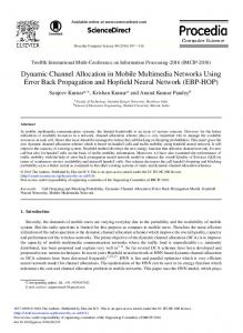
Infrastructure companies play a significant part in evolving the Internet, both in terms of where the interconnections are placed and made accessible and in terms of how much information can be carried how quickly. An 802.11 networking framework in which devices communicate with each other by first going through an Access Point (AP). In infrastructure mode, wireless devices can communicate with each other or can communicate with a wired network. When one AP is connected to wired network and a set of wireless stations it is referred to as a Basic Service Set (BSS). An Extended Service Set (ESS) is a set of two or more BSSs that form a single subnetwork. Most corporate wireless LANs operate in infrastructure mode because they require access to the wired LAN in order to use services such as file servers or printers.
Figure 2.1 Infrastructure Network
-۸-
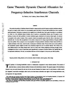
2.4 Wireless LAN Channels The 802.11b/g standards define 14 frequency channels for use with this technology. Depending on the country a user lives in and where he or she will be installing a WLAN, there are certain governmental restrictions for companies offering these products and consumers or businesses deploying these products. In North America, the FCC (Federal Communications Commission) and IC (Industry Canada) allow manufacturers and users to use channels 1 through 11which is the same case of Jordan, per ETSI approval (European Telecommunications Standards Institute); most of Europe can use channels 1 through 13, while in Japan, users have all 14 channels available.
Figure 2.2 Channels Distribution of frequency band
Even though there are 14 channel frequencies available for use, it should be noted that the actual channel frequency indicates the “center frequency” used by the transmitter and receiver for communication. An 802.11b radio signal consumes approximately 30 MHz of frequency spectrum, leaving a 5 MHz separation between center frequencies. This means that the signal extends out 15 MHz of the center frequency spectrum. As a result, the bandwidth required for each channel signal overlaps several adjacent frequencies. This leaves the typical Jordanian user with three channels available for use by access points (channels 1, 6, and 11) that are within radio range of adjacent access points.
-۹-
Figure 2-3 Bandwidth distribution between the operation channels
2.5 MADWIFI Network Drivers[2] P
MadWifi is short for Multiband Atheros Driver for Wireless Fidelity. In other words: it is a Linux kernel device driver for Atheros-based Wireless LAN devices. The driver works such that your WLAN card will appear as a normal network interface in the system. Additionally there is support for the Wireless Extensions API. This allows you to configure most aspects of the device using common wireless tools (ifconfig, iwconfig and friends). 1T
0T1
0T1
0T5
0T1
0T5
0T1
The code consists mainly of 4 parts: •
The net80211 stack from FreeBSD: Contains generic 802.11 functions and callback functions which can be overridden by devices. In the BSDs this stack supports multiple wlan hardware, but in madwifi it's obviously only used for atheros devices. • The ath part: Defines Atheros specific callbacks for the net80211 layer and accesses the hardware thru the About/HAL. • The About/HAL: Hardware Abstraction Layer. All access to the hardware has to go thru this closed source component which is maintained by Atheros. Unfortunately there is no documentation for it except the public interfaces in hal/ah.h. • The rate algorithms: Different algorithms for selecting the best transmission rate have been implemented by the rate modules in ath_rate. See UserDocs/RateControl
-۱۰-
MADWIFI supports many operational modes which are: • Sta: Station, a.k.a. infrastructure or managed. This device acting as typical WLAN client station. This is the default mode if not otherwise specified. • Ap: Access Point, a.k.a. master. This device acts as the Access Point for other WLAN client stations. • Adhoc: Ad-hoc. a.k.a. IBSS mode. This device is in a peer-to-peer(s) WLAN without the need for an Access Point. • Ahdemo: Ad-hoc Demo. This is an older, non-802.11 compliant, proprietary adhoc mode. Monitor: Monitor. This device can be used to "sniff" raw 802.11 frames. • Wds: Wireless Distribution System. This device can be used to create large wireless networks by linking several Access Points together.
-۱۱-
Chapter 3: Linux Kernel Programming
-۱۲-
Linux Kernel Programming
3.1 Unix Operating System [3] P
The Unix is a powerful computer operating system originally developed at AT&T Bell Laboratories. It is very popular among the scientific, engineering, and academic communities due to its multi-user and multi-tasking environment, flexibility and portability, electronic mail and networking capabilities, and the numerous programming, text processing and scientific utilities available. Unix was designed to be portable, multi-tasking and multi-user in a timesharing configuration. Unix systems are characterized by various concepts: the use of plain text for storing data; a hierarchical file system; treating devices and certain types of inter-process communication (IPC) as files; and the use of a large number of software tools, small programs that can be strung together through a command line interpreter using pipes, as opposed to using a single monolithic program that includes all of the same functionality. These concepts are collectively known as the Unix philosophy. 0T
0T
0T
0T
0T
0T
0T
0T
0T
0T
0T
0T
0T
0T
0T
0T
0T
0T
0T
0T
0T
0T
0T
0T
0T
0T
0T
0T
0T
0T
0T
0T
0T
0T
Under Unix, the "operating system" consists of many of these utilities along with the master control program, the kernel. The kernel provides services to start and stop programs, handles the file system and other common "low level" tasks that most programs share, and, perhaps most importantly, schedules access to hardware to avoid conflicts if two programs try to access the same resource or device simultaneously. To mediate such access, the kernel was given special rights on the system, leading to the division between user-space and kernel-space. 0T
0T
0T
0T
0T
0T
0T
0T
0T
0T
The microkernel concept was introduced in an effort to reverse the trend towards larger kernels and return to a system in which most tasks were completed by smaller utilities. In an era when a "normal" computer consisted of a hard disk for storage and a data terminal for input and output (I/O), the Unix file model worked quite well as most I/O was "linear". However, modern systems include networking and other new devices. As graphical user interfaces developed, the file model proved inadequate to the task of handling asynchronous events such as those generated by a mouse, and in the 1980s non-blocking I/O and the set of inter-process communication mechanisms was augmented (sockets, shared memory, message queues, semaphores), and functionalities such as network protocols were moved out of the kernel. 0T
0T
0T
0T
0T
0T
0T
0T
0T
0T
0T
0T
0T
0T
-۱۳-
0T
0T
0T
0T
0T
0T
0T
0T
0T
0T
3.2 Linux Operating System Linux is a generic term referring to the family of Unix-like computer operating systems based on the Linux kernel. Their development is one of the most prominent examples of free and open source software collaboration; typically all the underlying source code can be used, freely modified, and redistributed, both commercially and non-commercially, by anyone under licenses such as the GNU General Public License. 1T
0T1
0T1
0T1
0T1
0T1
0T1
0T1
0T1
0T1
0T1
0T1
0T1
0T1
0T1
0T1
0T1
0T1
0T1
0T1
0T1
3.3 Linux Networking Linux has been designed with networking in mind and it is prepared to handle multi network models. Setting up a network on Linux machine is surprisingly simple, because linux handles most of the work. Linux supports most of the major protocols and quite a few of the minor ones. A lot of networking options will run quite acceptably on the minimal hardware configurations using wireless tools which are built in linux kernel. Connecting to a wireless network using these commands is really important when you want to create a script need like these configurations. That’s one of beauties of Linux.
3.4 Kernel Computing[4] P
3.4.1 Introduction The kernel is the central component of most computer operating systems; it is a bridge between applications and the actual data processing done at the hardware level. The kernel's responsibilities include managing the system's resources (the communication between hardware and software components). Usually as a basic component of an operating system, a kernel can provide the lowest-level abstraction layer for the resources (especially processors and I/O devices) that application software must control to perform its function. It typically makes these facilities available to application processes through inter-process communication mechanisms and system calls. 0T
0T
0T
0T
0T
0T
0T
0T
0T
0T
0T
0T
0T
0T
0T
0T
0T
0T
0T
0T
0T
0T
0T
0T
0T
0T
0T
0T
-۱٤-
0T
0T
0T
0T
0T
0T
0T
0T
Figure 3.4 Data processing levels
Operating system tasks are done differently by different kernels, depending on their design and implementation. While monolithic kernels will try to achieve these goals by executing all the operating system code in the same address space to increase the performance of the system, microkernel run most of the operating system services in user space as servers, aiming to improve maintainability and modularity of the operating system. A range of possibilities exists between these two extremes. 0T
0T
0T
0T
0T
0T
0T
0T
0T
0T
0T
0T
0T
0T
0T
0T
Most operating systems rely on this kernel concept. The existence of a kernel is a natural consequence of designing a computer system as a series of abstraction layers, each relying on the functions of layers beneath itself. The kernel, from this viewpoint, is simply the name given to the lowest level of abstraction that is implemented in software. In order to avoid having a kernel, one would have to design all the software on the system not to use abstraction layers; this would increase the complexity of the design to such a point that only the simplest systems could feasibly be implemented. 0T
0T
0T
0T
0T
0T
0T
0T
0T
0T
While it is today mostly called the kernel, originally the same part of the operating system was also called the nucleus or core, and was originally conceived as containing only the essential support features of the operating system. 0T
0T
0T
0T
0T
0T
0T
0T
Kernel development is considered one of the most complex and difficult tasks in programming. Its central position in an operating system implies the necessity for good performance, which defines the kernel as a critical piece of software and makes its correct design and implementation difficult. For various reasons, a kernel might not even be able to use the abstraction mechanisms it provides to other software. Such reasons include memory management concerns (for example, a user-mode function might rely on memory being subject 0T
0T
0T
0T
0T
0T
-۱٥-
to demand paging, but as the kernel itself provides that facility it cannot use it, because then it might not remain in memory to provide that facility) and lack of reentrancy, thus making its development even more difficult for software engineers. 0T
0T
0T
0T
A kernel will usually provide features for low-level scheduling of processes (dispatching), inter-process communication, process synchronization, context switching, manipulation of process control blocks, interrupt handling, process creation and destruction, and process suspension and resumption. 1T
0T1
0T1
0T1
0T1
0T1
0T1
0T1
0T1
0T1
0T1
0T1
0T1
3.4.2 Kernel basic facilities 1T
The kernel's primary purpose is to manage the computer's resources and allow other programs to run and use these resources. Typically, the resources consist of: •
The Central Processing Unit (CPU, the processor). This is the most central part of a computer system, responsible for running or executing programs on it. The kernel takes responsibility for deciding at any time which of the many running programs should be allocated to the processor or processors (each of which can usually run only one program at a time) • The computer's memory. Memory is used to store both program instructions and data. Typically, both need to be present in memory in order for a program to execute. Often multiple programs will want access to memory, frequently demanding more memory than the computer has available. The kernel is responsible for deciding which memory each process can use, and determining what to do when not enough is available. • Any Input/ Output (I/O) devices present in the computer, such as keyboard, mouse, disk drives, printers, displays, etc. The kernel allocates requests from applications to perform I/O to an appropriate device (or subsection of a device, in the case of files on a disk or windows on a display) and provides convenient methods for using the device (typically abstracted to the point where the application does not need to know implementation details of the device). Key aspects necessary in resource managements are the definition of an execution domain (address space) and the protection mechanism used to mediate the accesses to the resources within a domain. Kernels also usually provide methods for synchronization and communication between processes (called inter-process communication or IPC). 0T
0T
0T
0T
0T
0T
0T
0T
0T
0T
0T
0T
A kernel may implement these features itself, or rely on some of the processes it runs to provide the facilities to other processes, although in this case it must provide some means of IPC to allow processes to access the facilities provided by each other.
-۱٦-
Finally, a kernel must provide running programs with a method to make requests to access these facilities.
3.4.2.1
Process management
7T
The main task of a kernel is to allow the execution of applications and support them with features such as hardware abstractions. A process defines which memory portions the application can access. (For this introduction, process, application and program are used as synonyms.) Kernel process management must take into account the hardware built-in equipment for memory protection. 0T
0T
0T
0T
0T
0T
To run an application, a kernel typically sets up an address space for the application, loads the file containing the application's code into memory (perhaps via demand paging), sets up a stack for the program and branches to a given location inside the program, thus starting its execution. 0T
0T
0T
0T
0T
0T
0T
0T
Multi-tasking kernels are able to give the user the illusion that the number of processes being run simultaneously on the computer is higher than the maximum number of processes the computer is physically able to run simultaneously. Typically, the number of processes a system may run simultaneously is equal to the number of CPUs installed (however this may not be the case if the processors support simultaneous multithreading). 0T
0T
0T
0T
In a pre-emptive multitasking system, the kernel will give every program a slice of time and switch from process to process so quickly that it will appear to the user as if these processes were being executed simultaneously. The kernel uses scheduling algorithms to determine which process is running next and how much time it will be given. The algorithm chosen may allow for some processes to have higher priority than others. The kernel generally also provides these processes a way to communicate; this is known as inter-process communication(IPC) and the main approaches are shared memory, message passing and remote procedure calls (see concurrent computing). 0T
0T
0T
0T
0T
0T
0T
0T
0T
0T
0T
0T
0T
0T
0T
0T
0T
0T
0T
0T
0T
0T
Other systems (particularly on smaller, less powerful computers) may provide co-operative multitasking, where each process is allowed to run uninterrupted until it makes a special request that tells the kernel it may switch to another process. Such requests are known as "yielding", and typically occur in response to requests for interprocess communication, or for waiting for an event to occur. The operating system might also support multiprocessing (SMP or Non-Uniform Memory Access); in that case, different programs and threads may run on different processors. A kernel for such a system must be designed to be re-entrant, meaning that it may safely run two different parts of its code simultaneously. This typically means 0T
0T
-۱۷-
0T
0T
0T
0T
0T
0T
0T
0T
providing synchronization mechanisms (such as spinlocks) to ensure that no two processors attempt to modify the same data at the same time. 0T
3.4.2.2 7T
0T
0T
0T
0T
0T
Memory management
The kernel has full access to the system's memory and must allow processes to safely access this memory as they require it. Often the first step in doing this is virtual addressing, usually achieved by paging and/or segmentation Virtual addressing allows the kernel to make a given physical address appear to be another address, the virtual address. Virtual address spaces may be different for different processes; the memory that one process accesses at a particular (virtual) address may be different memory from what another process accesses at the same address. This allows every program to behave as if it is the only one (apart from the kernel) running and thus prevents applications from crashing each other. 0T
0T
0T
0T
0T
0T
0T
0T
On many systems, a program's virtual address may refer to data which is not currently in memory. The layer of indirection provided by virtual addressing allows the operating system to use other data stores, like a hard drive, to store what would otherwise have to remain in main memory (RAM). As a result, operating systems can allow programs to use more memory than the system has physically available. When a program needs data which is not currently in RAM, the CPU signals to the kernel that this has happened, and the kernel responds by writing the contents of an inactive memory block to disk (if necessary) and replacing it with the data requested by the program. The program can then be resumed from the point where it was stopped. This scheme is generally known as demand paging. 0T
0T
0T
0T
Virtual addressing also allows creation of virtual partitions of memory in two disjointed areas, one being reserved for the kernel (kernel space) and the other for the applications (user space). The applications are not permitted by the processor to address kernel memory, thus preventing an application from damaging the running kernel. This fundamental partition of memory space has contributed much to current designs of actual general-purpose kernels and is almost universal in such systems, although some research kernels (e.g. Singularity) take other approaches. 0T
3.4.2.3 7T
0T
Device management
To perform useful functions, processes need access to the peripherals connected to the computer, which are controlled by the kernel through device drivers. For example, to show the user something on the screen, an application would make a request to the kernel, which would forward the request to its display driver, which is then responsible for actually plotting the character/pixel. 0T
0T
-۱۸-
0T
0T
0T
0T
A kernel must maintain a list of available devices. This list may be known in advance (e.g. on an embedded system where the kernel will be rewritten if the available hardware changes), configured by the user (typical on older PCs and on systems that are not designed for personal use) or detected by the operating system at run time (normally called plug and play). 0T
0T
In a plug and play system, a device manager first performs a scan on different hardware buses, such as Peripheral Component Interconnect (PCI) or Universal Serial Bus (USB), to detect installed devices, then searches for the appropriate drivers. 0T
0T
0T
0T
0T
0T
0T
0T
0T
0T
As device management is a very OS-specific topic, these drivers are handled differently by each kind of kernel design, but in every case, the kernel has to provide the I/O to allow drivers to physically access their devices through some port or memory location. Very important decisions have to be made when designing the device management system, as in some designs accesses may involve context switches, making the operation very CPU-intensive and easily causing a significant performance overhead. 0T
0T
3.4.2.4 7T
0T
0T
0T
0T
System calls
To actually perform useful work, a process must be able to access the services provided by the kernel. This is implemented differently by each kernel, but most provide a C library or an API, which in turn invokes the related kernel functions. 0T
0T
0T
0T
The method of invoking the kernel function varies from kernel to kernel. If memory isolation is in use, it is impossible for a user process to call the kernel directly, because that would be a violation of the processor's access control rules. A few possibilities are: Using a software-simulated interrupt. This method is available on most hardware, and is therefore very common. b. Using a call gate. A call gate is a special address stored by the kernel in a list in kernel memory at a location known to the processor. When the processor detects a call to that address, it instead redirects to the target location without causing an access violation. This requires hardware support, but the hardware for it is quite common. c. Using a special system call instruction. This technique requires special hardware support, which common architectures (notably, x86) may lack. System call instructions have been added to recent models of x86 processors, however, and some (but not all) operating systems for PCs make use of them when available. d. Using a memory-based queue. An application that makes large numbers of requests but does not need to wait for the result of each may add details of requests to an area of memory that the kernel periodically scans to find requests. a.
0T
0T
0T
0T
0T
0T
-۱۹-
3.4.3 Kernel Programming The system programs use the tools provided by the kernel to implement the various services required from an operating system. System programs, and all other programs, run `on top of the kernel', in what is called the user mode. The difference between system and application programs is one of intent: applications are intended for getting useful things done (or for playing, if it happens to be a game), whereas system programs are needed to get the system working. A word processor is an application; telnet is a system program. The difference is often somewhat blurry, however, and is important only to compulsive categorizers. 0T
0T
0T
0T
0T
0T
An operating system can also contain compilers and their corresponding libraries (GCC and the C library in particular under Linux), although not all programming languages need be part of the operating system. Documentation, and sometimes even games, can also be part of it. Traditionally, the operating system has been defined by the contents of the installation tape or disks; with Linux it is not as clear since it is spread all over the FTP sites of the world.
3.5 Bash Shell scripting A free software Unix shell written for the GNU Project. Its name is an acronym which stands for Bourne-again shell. The name is a pun on the name of the Bourne shell (sh), an early and important Unix shell written by Stephen Bourne and distributed with Version 7 Unix circa 1978, and the phrase born again. Bash was created in 1987 by Brian Fox. In 1990 Chet Ramey became the primary maintainer. 1T
0T1
0T1
0T1
0T1
0T1
0T1
0T1
0T1
0T1
0T1
0T1
P
0T1
0T1
0T1
0T1
0T1
0T1
0T1
0T1
0T1
0T1
0T1
0T1
0T1
0T1
0T1
0T1
0T1
0T1
0T1
0T1
0T1
0T1
0T1
0T1
0T1
P
0T1
0T1
The Bash command syntax is a superset of the Bourne shell command syntax. The vast majority of Bourne shell scripts can be executed by Bash without modification, with the exception of Bourne shell scripts stumbling into fringe syntax behavior interpreted differently in Bash (nested parentheses broke under Bash, for example, in the Mozilla startup script some years back), or attempting to run a system command matching a newer bash builtin, etc. Bash command syntax includes ideas drawn from the Korn shell (ksh) and the C shell (csh) such as command line editing, command history, the directory stack, the $RANDOM and $PPIDvariables, and POSIX command substitution syntax $(…). When used as an interactive command shell and pressing the tab key, Bash automatically uses command line completion to match partly typed program names, filenames and variable names. 0T
0T
0T
0T
0T
0T
0T
0T3
0T3
0T
0T
0T3
3T
0T
0T
0T
0T
0T
0T
0T
0T
0T
0T
0T
0T
0T
0T
0T
0T
0T
0T3
3T
0T
0T
Bash's syntax has many extensions which the Bourne shell lacks. Bash can perform integer calculations without spawning external processes, unlike the Bourne shell. Bash uses
-۲۰-
the ((…)) command and the $((…)) variable syntax for this purpose. Bash syntax simplifies I/O redirection in ways that are not possible in the traditional Bourne shell. For example, Bash can redirect standard output (stdout) and standard error (stderr) at the same time using the &> operator. This is simpler to type than the Bourne shell equivalent 'command > file 2>&1'. Bash function declarations (using the key word 'function') are not compatible with Bourne/Korn/POSIX/C-shell scripts. Due to these and other differences, Bash shell scripts are rarely runnable under the Bourne or Korn shell interpreters unless deliberately written with that compatibility in mind, which is becoming less common as Linux becomes more widespread. 0T
0T3
0T3
0T
0T
0T
0T
0T
0T3
0T3
0T
0T3
0T3
0T
0T
0T
0T
0T
0T
0T
0T
0T
3T
-۲۱-
3T
Chapter 4: Network Analysis
-۲۲-
4.1 Introduction Network analysis is the process of capturing network traffic and inspecting it closely to determine what is happening on the network. A network analyzer decodes, or dissects, the data packets of common protocols and displays the network traffic in human-readable format. Network analysis is also known by several other names: traffic analysis, protocol analysis, sniffing, packet analysis, and eavesdropping to name a few. Sniffing tends to be one of the most popular terms in use today. However, as you will see later in this chapter, due to malicious users it has had a negative connotation in the past. A network analyzer can be a standalone hardware device with specialized software, or it can simply be software that you install on your desktop or laptop computer. Network analyzers are available both free and commercially. Differences between network analyzers tend to depend on features such as the number of supported protocol decodes, the user interface, and graphing and statistical capabilities. Other differences include inference capabilities, such as expert analysis features, and the quality of packet decodes. Although several network analyzers all decode the same protocols, some may decode better than others. A network analyzer is a combination of hardware and software. Although there are differences in each product, a network analyzer is composed of five basic parts: Hardware: Most network analyzers are software-based and work with standard operating systems (OSs) and network interface cards (NICs). However, there are some special hardware network analyzers that offer additional benefits such as analyzing hardware faults including: Cyclic Redundancy Check (CRC) errors, voltage problems, cable problems, jitter, jabber, negotiation errors, etc. Some network analyzers only support Ethernet or wireless adapters, while others support multiple adapters and allow users to customize their configuration. Sometimes you will also need a hub or a cable tap to connect to the existing cable. Capture driver: This is the part of a network analyzer that is responsible for actually capturing the raw network traffic from the cable. It will also filter out the traffic that you want and store the data in a buffer. This is the core of a network analyzer and you cannot capture data without it. Buffer: This component stores the captured data. Data can be stored in a buffer until it is full, or in a rotation method such as “round robin” where the newest data replaces the oldest data. Buffers can be disk-based or memory-based.
-۲۳-
Real-time analysis: This feature analyzes the data as it comes off the cable. Some network analyzers use this to find network performance issues, and network intrusion detection systems do this to look for signs of intruder activity. Decode: This component displays the contents of the network traffic with descriptions so that it is human-readable. Decodes are specific to each protocol, so network analyzers tend to vary in the number of decodes they currently support. However, new decodes are constantly being added to network analyzers.
4.2 Wireshark Program [6] P
Wireshark (also known as Ethereal) is a network protocol analyzer that enables you to capture and examine data from a live network or from a capture file on disk. You can interactively browse the capture data and view summary and detail information for each packet. Wireshark has several powerful features, including a rich display filter language and the ability to view the reconstructed stream of a TCP session. It can read capture files from tcpdump (libpcap), NAI Sniffer (compressed and uncompressed), Sniffer Pro, NetXray, snoop, Shomiti Surveyor, AIX s iptrace, Microsoft Network Monitor, Novell s LANalyzer, RADCOM s WAN/LAN Analyzer, HP-UX nettl, ISDN4BSD, Cisco Secure IDS iplog, the pppd log (pppdump-format), and the AG Group s/ Wildpacket Etherpeek. It can also read traces made from Lucent/Ascend WAN routers and Toshiba ISDN routers. Any of these files can be compressed with gzip and Wireshark will decompress them on the fly. 1T
4.3 Iperf Program [5] 1T
P
Iperf is a commonly used network testing tool that can create TCP and UDP data streams and measure the throughput of a network that is carrying them. Iperf is a modern tool for network performance measurement written in C++. 0T
0T
0T
0T
0T
0T
0T
0T
0T
0T
0T
0T
Iperf allows the user to set various parameters that can be used for testing a network, or alternately for optimizing or tuning a network. Iperf has a client and server functionality, and can measure the throughput between the two ends, either unidirectionally or bi-directionally. It is open source software and runs on various platforms including Linux, Unix and Windows. It is supported by the National Laboratory for Applied Network Research. 0T
0T
0T
-۲٤-
0T
0T
0T
0T
0T
0T
0T
When used for testing UDP capacity, Iperf allows the user to specify the datagram size and provides results for the datagram throughput and the packet loss. 0T
0T
0T
0T
0T
0T
0T
0T
0T
0T
0T
0T
When used for testing TCP capacity, Iperf measures the throughput of the payload. One thing to note is that Iperf uses 1024*1024 for megabytes and 1000*1000 for megabits 0T
0T
0T
0T
0T
0T
0T
0T
Typical Iperf output contains a time stamped report of the amount of data transferred and the throughput measured. Iperf is significant as it is a standardized tool that can be run over any network and output standardized performance measurements. Thus it can be used for comparison of wired and wireless networking equipment and technologies in an unbiased way. As it is open source, the measurement methodology can be scrutinized by user. P
P
-۲٥-
PART II: DCAMP Dynamic Channel Allocation MAC Protocol
-۲٦-
Chapter 5 DCAMP Description and Design
-۲۷-
In this chapter, we describe the functionality and design of our protocol DCAMP. First, we give a short introduction about the Distributed Coordination Function (DCF) of IEEE 802.11 WLANs and then we explain DCAMP and its design in details.
5.1
Distributed Coordination Function (DCF) 5.1.1
DCF Mechanism [7] P
P
Distributed Coordination Function (DCF) is the fundamental MAC technique of the IEEE 802.11 based WLAN standard. The DCF employs a carrier sense multiple access protocol with collision avoidance (CSMA/CA) which is described below. 0T
0T
0T
0T
0T
0T
0T
0T
0T
0T
0T
0T
0T
0T
A station wishing to transmit listens for the channel status for a DIFS interval. If the channel is busy during the DIFS interval, the station defers its transmission in a network where a number of stations contend for the wireless medium. If multiple stations sense the channel busy and defer their access, they will also virtually and simultaneously find that the channel is released and then try to seize the channel again. As a result, collisions may occur. In order to avoid such collisions, DCF also specifies random backoff, which forces a station to defer its access to the channel for an extra period. The length of the backoff period is determined by the following equation: 0T
0T
0T
0T
BackoffTime = random ( ) * aSlotTime R
R
Where: random ( ) is a random number. aSlotTime is one slot time from a group of slot times that the channel divided to.
The DCF also has an optional virtual carrier sense mechanism that exchanges short Requestto-send (RTS) and Clear-to-send (CTS) frames between source and destination stations during the intervals between the data frame transmissions. The DCF includes a positive acknowledge scheme, which means that if a frame is successfully received by the destination it is addressed to, the destination needs to send an ACK frame to notify the source of the successful reception.
-۲۸-
5.1.2
Retry Counters
Retry counters are counters that incremented each time a packet is being retransmitted. A packet is retransmitted when the transmission fails. A transmission could fail due to three reasons; channel fading, collided packets and lost acknowledgements. Two types of retry counters are used by the DCF; the short retry counter and the long retry counter. Short retry counter is incremented with each retransmitted management packet, such as RTC, CTS and ACK. While the long retry counter is incremented with each retransmitted data packet.
Figure 5.1 Backoff in DCF
As shown in figure 5.1, when the backoff period due to a successful transmission has elapsed, a station attempts to transmit the next consecutive packet. When that packet is collided, a station will defer its transmission with a bigger backoff period and waits for that period to be elapsed in order to retransmit that packet again. Meanwhile, the long retry counter will be incremented with each retransmission operation. This whole process continues until the long retry counter reaches its maximum value. Then the current packet will be discarded. 5.1.3
Congestion
As explained in the previous sections, a station depends on the standard DCF mechanism to avoid collisions. But this mechanism is not suitable when a station works with other stations in a heavy congested environment. This case leads to have a congested channel that mostly found busy by a station trying to transmit. This increases the probability of collision and the probability of delay. As a result, the average throughput will decrease.
-۲۹-
5.2 DCAMP Description In this protocol, we propose a new channel allocation mechanism in order to solve the problem of congestion that described in the previous section. This achieved by giving the station the ability to switch the channel during a downstream transmission. The channel switching operation used in DCAMP is Packet Based modus operandi, which means that the status of each data packet is the Governor for this operation to occur or not. 1T
In our implementation, we applied DCAM on an Access point of infrastructure network. We also rely on the long retry counter which is described in the previous section to be the crucial condition of the switching operation. According to it, the AP can decide whether it has to perform channel switching operation or not. So, if an AP is operating on certain channel and the long retry counter for a packet reaches certain threshold, the AP will terminate the communication on the current channel and switch to another new one. On the new channel, the AP will continue the transmission until the long retry counter for that packet or other one reaches another threshold. Then, the AP will return back to the original channel. Therefore, instead of making the AP suffering on certain channel all the time. We offer a new way to avoid that in order to improve the total throughput of the network. 1T
In DCAMP, we assume that the receivers are able to recover the connection back by themselves using certain procedure which will be discussed later.
-۳۰-
Figure 5.2 DCAMP Description.
As shown in figure 5.2b, figure 5.2c and figure 5.3, after reserving channel 1, the AP starts normally the transmission on it. During transmission, if the long retry counter for a certain packet reaches four, the AP will terminate the current communication on channel 1and switch to channel 11. If not, the AP will stay on channel 1. On channel 11, the AP will try to resend the same packet again. If the long retry counter for that packet reaches six, the AP will drop that packet and return back to the original channel. Otherwise, the AP will continue the transmission on the new channel. If another packet is being retransmitted six times, it will return back to channel 1 and it will try to resend it there and so on. 1T
1T
1T
The reason behind choosing channel 1 and channel 11in DCAMP, is to avoid the interference between the adjacent frequencies and to ensure that the operating frequencies are separated and don’t affect each other. Moreover, we choose the value of the long retry counter on channel 1 to be four, in order to give the AP a reasonable number of retries before switching to another channel. And six for channel 11, in order to reduce hopping times that could affect the stability of the connection with the stations. As a result, each packet still keeps its maximum number of retries which is ten.
-۳۱-
Figure 5.3 DCAMP Flow Chart
-۳۲-
Chapter 6 DCAMP Implementation
-۳۳-
In this chapter, we describe the steps of our implementation of DCAMP in a real network and we explain the modifications that were implemented in Madwifi driver in order to present a new working model.
6.1 System Design In this section, we describe how the system is configured in order to apply DCAMP.
6.1.1
Network Configuration
In our system, we used eleven wireless cards installed on ten machines, the specifications of each device is as follows: • Eleven TP-link wn651g wireless cards have Atheros shipset and operating by Madwifi driver. • Ten Dell machines. We configured those wireless cards to act as three separated networks and one monitor station as follows: I. Network A U
• Includes three wireless cards; one operating as an AP (Master mode) and the others as Stations. • This network is the fundamental network where we implemented DCAMP. By default this network is operating on channel 1, and the AP in this network has the ability to switch to channel 11 as well. II. Network B U
• •
Includes three wireless cards; one operating as an AP and the other cards as stations. This network is fixed to work on channel 1.
III. Network C U
•
Includes three wireless cards; one operating as an AP and the other two cards as Stations.
-۳٤-
•
This network is fixed to work on channel 11.
IV. Monitoring Station U
• Includes two wireless cards running on the same machine, each one monitor different channel • The two cards were configured to work in Monitor Mode, and they are installed on the same machine in order to ensure the synchronization between them. Note: All configurations of the networks were done using Shell programming in (.bashrc) file. The configurations of Network A U
The Configurations of the AP U
•
sudo service network-manager stop
This command completely eliminates the network manager from controlling the connection setup of the network; this ensures that the configurations of the network and the setup of the connection are only done within the terminal space. •
sudo wlanconfig ath0 destroy
This command demolishes any past interface that named by ath0 •
sudo wlanconfig ath0 create wlandev wifi0 wlanmode ap
This command creates a new interface called ath0 operating as an Access point (ap). •
sudo iwconfig ath0 essid test
Set the network name to test •
sudo iwconfig ath0 channel 1
Set the operating channel to channel 1. •
Sudo iwconfig ath0 rate 54M fixed
-۳٥-
Set the transmission rate to 54Mbps. •
sudo ifconfig ath0 up
Bring the interface up. •
sudo ifconfig ath0 169.255.0.2
Set a static IP address for ath0. •
sudo iwpriv ath0 ff 0
Disable the Fast Framing feature. •
sudo iwpriv ath0 ar 0
Disable the Adaptive Radio feature. •
sudo iwpriv ath0 burst 0
Disable the Frame Bursting feature. The configurations of the first station U
•
sudo service network-manager stop
This command completely eliminates the network manager from controlling our connection setup; this ensures that the configurations of the network and the setup of the connection are only done within the terminal space. •
sudo wlanconfig ath0 destroy
This command demolishes any past interface that named by ath0. •
sudo wlanconfig ath0 create wlandev wifi0 wlanmode sta
This command creating a new interface called ath0 and operating as a Station (sta). •
sudo iwconfig ath0 essid test
-۳٦-
Set the network name to test. •
sudo iwconfig ath0 channel 1
Set the operating channel to channel 1. •
Sudo iwconfig ath0 rate 54M fixed
Set the transmission rate to 54Mbps. •
sudo ifconfig ath0 up
Bring the interface up. •
sudo ifconfig ath0 169.255.3.2
Specify a static IP address for ath0. •
sudo iwpriv ath0 ff 0
Disable the Fast Framing feature. •
sudo iwpriv ath0 ar 0
Disable the Adaptive Radio feature. •
sudo iwpriv ath0 burst 0
Disable the Frame Bursting feature. The configurations of the second station U
•
sudo service network-manager stop
This command completely eliminates the network manager from controlling our connection setup; this ensures that the configurations of the network and the connection setup are only done within the terminal space. •
sudo wlanconfig ath0 destroy
-۳۷-
This command destroys any past interface that named by ath0. •
sudo wlanconfig ath0 create wlandev wifi0 wlanmode sta
This command creating a new interface called ath0 operating as a Station (sta). •
sudo iwconfig ath0 essid test
Set the network name to test. •
sudo iwconfig ath0 channel 1
Set the operating channel to channel 1. •
Sudo iwconfig ath0 rate 54M fixed
Set the transmission rate to 54Mbps. •
sudo ifconfig ath0 up
Bring the interface up. •
sudo ifconfig ath0 169.255.4.2
Set a static IP address for ath0. •
sudo iwpriv ath0 ff 0
Disable the Fast Framing feature. •
sudo iwpriv ath0 ar 0
Disable the Adaptive Radio feature. •
sudo iwpriv ath0 burst 0
Disable the Frame Bursting feature
-۳۸-
The configurations of Network B U
The configurations of the AP U
•
sudo service network-manager stop
This command completely eliminates the network manager from controlling our setup; this ensures that the configurations of the network and connection setup are only done within the terminal space. •
sudo wlanconfig ath0 destroy
This command destroys any past interface that named by ath0. •
sudo wlanconfig ath0 create wlandev wifi0 wlanmode ap
This command creating a new interface called ath0 operating as an Access point. •
sudo iwconfig ath0 essid test1
Set the network name to test1. •
sudo iwconfig ath0 channel 1
Set the operating channel to channel 1. •
Sudo iwconfig ath0 rate 54M fixed
Set the transmission rate to 54Mbps. •
sudo ifconfig ath0 up
Bring the interface up. •
sudo ifconfig ath0 169.255.6.2
Set a static IP address for ath0.
-۳۹-
•
sudo iwpriv ath0 ff 0
Disable the Fast Framing feature. •
sudo iwpriv ath0 ar 0
Disable the Adaptive Radio feature. •
sudo iwpriv ath0 burst 0
Disable the Frame Bursting feature
The configurations of the first station U
•
sudo service network-manager stop
This command completely eliminates the network manager from controlling our connection setup; this ensures that the configuration and the setup of the connection are only done within the terminal space. •
sudo wlanconfig ath0 destroy
This command destroys any past interface that named by ath0 •
sudo wlanconfig ath0 create wlandev wifi0 wlanmode sta
This command creating a new interface called ath0 operating as a sta (Station). •
sudo iwconfig ath0 essid test1
Setting the network name to test1 •
sudo iwconfig ath0 channel 1
Set the operating channel to channel 1. •
Sudo iwconfig ath0 rate 54M fixed
-٤۰-
Set the transmission rate to 54Mbps. •
sudo ifconfig ath0 up
Bring the interface up. •
sudo ifconfig ath0 169.255.5.2
Set a static IP address. •
sudo iwpriv ath0 ff 0
Disable the Fast Framing feature. •
sudo iwpriv ath0 ar 0
Disable the Adaptive Radio feature. •
sudo iwpriv ath0 burst 0
Disable the Frame Bursting feature
The configurations of the second station U
•
sudo service network-manager stop
This command completely eliminates the network manager from controlling our setup; this ensures that the configuration and the setup of the connection are only done within the terminal space. •
sudo wlanconfig ath0 destroy
This command destroys any past interface that named by ath0 •
sudo wlanconfig ath0 create wlandev wifi0 wlanmode sta
This command creating a new interface called ath0 operating as a sta (Station).
-٤۱-
•
sudo iwconfig ath0 essid test1
Set the network name to test1. •
sudo iwconfig ath0 channel 1
Set the channel to channel 1. •
Sudo iwconfig ath0 rate 54M fixed
Set the transmission rate to 54Mbps. •
sudo ifconfig ath0 up
Bring the interface up. •
sudo ifconfig ath0 169.255.5.2
Set a static IP address for ath0. •
sudo iwpriv ath0 ff 0
Disable the Fast Framing feature in. •
sudo iwpriv ath0 ar 0
Disable the Adaptive Radio feature. •
sudo iwpriv ath0 burst 0
Disable the Frame Bursting feature
-٤۲-
The configurations of Network C U
The configurations of the AP U
•
sudo service network-manager stop
This command completely eliminates the network manager from controlling our setup; this ensures that the configurations of the network and the setup of the connection are only done within the terminal space. •
sudo wlanconfig ath0 destroy
This command destroys any past interface that named by ath0. •
sudo wlanconfig ath0 create wlandev wifi0 wlanmode ap
This command creates a new interface called ath0 and operates as an Access point. •
sudo iwconfig ath0 essid test2
Set the network name to test2. •
sudo iwconfig ath0 channel 11
Set the channel to channel 11. •
Sudo iwconfig ath0 rate 54M fixed
Set the transmission rate to 54Mbps. •
sudo ifconfig ath0 up
Bring the interface up. •
sudo ifconfig ath0 169.255.1.2
Set a static IP address. •
sudo iwpriv ath0 ff 0
-٤۳-
Disable the Fast Framing feature. •
sudo iwpriv ath0 ar 0
Disable the Adaptive Radio feature. •
sudo iwpriv ath0 burst 0
Disable the Frame Bursting feature
The configurations of the first station U
•
sudo service network-manager stop
This command completely eliminates the network manager from controlling our setup; this ensures that the configurations of the network and the setup of the connection are only done within the terminal space. •
sudo wlanconfig ath0 destroy
This command destroys any past interface that named by ath0. •
sudo wlanconfig ath0 create wlandev wifi0 wlanmode sta
This command creates a new interface called ath0 which operates as a Station. •
sudo iwconfig ath0 essid test2
Set the network name to test2. •
sudo iwconfig ath0 channel 11
Set the channel to channel 11. •
Sudo iwconfig ath0 rate 54M fixed
Set the transmission rate to 54Mbps.
-٤٤-
•
sudo ifconfig ath0 up
Bring the interface up. •
sudo ifconfig ath0 169.255.8.2
Set a static IP address. •
sudo iwpriv ath0 ff 0
Disable the Fast Framing feature. •
sudo iwpriv ath0 ar 0
Disable the Adaptive Radio feature. •
sudo iwpriv ath0 burst 0
Disable the Frame Bursting feature
The second station configurations U
•
sudo service network-manager stop
This command completely eliminates the network manager from controlling our setup; this ensures that the configurations of the network and the setup of the connection are only done within the terminal space. •
sudo wlanconfig ath0 destroy
This command destroys any past interface that named by ath0. •
sudo wlanconfig ath0 create wlandev wifi0 wlanmode sta
This command creating a new interface called ath0 that operates as a Station. •
sudo iwconfig ath0 essid test2
-٤٥-
Set the network name to test2. •
sudo iwconfig ath0 channel 11
Set the channel to channel 11. •
Sudo iwconfig ath0 rate 54M fixed
Set the transmission rate to 54Mbps. •
sudo ifconfig ath0 up
Bring the interface up. •
sudo ifconfig ath0 169.255.9.2
Set a static IP address for ath0. •
sudo iwpriv ath0 ff 0
Disable the Fast Framing feature. •
sudo iwpriv ath0 ar 0
Disable the Adaptive Radio feature. •
sudo iwpriv ath0 burst 0
Disable the Frame Bursting feature
Monitor Mode Configurations U
•
sudo service network-manager stop
This command completely eliminates the network manager from controlling our setup; this ensures that the configurations of the network and the setup of the connection are only done within the terminal space.
-٤٦-
• • •
sudo wlanconfig ath0 destoy sudo wlanconfig ath1 destoy sudo wlanconfig ath2 destoy
Demolish any past interfaces.
Configure the first card to monitor channel 1 U
•
sudo wlanconfig ath0 create wlandev wifi0 wlanmode monitor
Create an interface called ath0 which operates in monitor mode. •
sudo iwconfig ath0 channel 1
Set the interface to monitor channel 1 •
sudo iwconfig ath0 essid test
Set the interface to monitor the network that has the essid test •
sudo ifconfig ath0 up
Bring the interface up. •
sudo iwpriv ath0 ff 0
Disable the Fast Framing feature. •
sudo iwpriv ath0 ar 0
Disable the Adaptive Radio feature. •
sudo iwpriv ath0 burst 0
Disable the Frame Bursting feature
-٤۷-
Configure the second card to monitor channel 11 U
•
sudo wlanconfig ath1 create wlandev wifi0 wlanmode monitor
Create an interface called ath1 operating in monitor mode. •
sudo iwconfig ath1 channel 11
Set the interface to monitor channel 11. •
sudo iwconfig ath1 essid test
Set the interface to monitor the network that has the essid test •
sudo ifconfig ath1 up
Bring the interface up. •
sudo iwpriv ath1 ff 0
Disable the Fast Framing feature. •
sudo iwpriv ath1 ar 0
Disable the Adaptive Radio feature. •
sudo iwpriv ath1 burst 0
Disable the Frame Bursting feature Note: We observe from the previous section that the configurations of the three networks are almost the same, but the major distinctive differences are; the network name (essid), the operating channel and the IP addresses.
-٤۸-
6.1.2 Connection setup In this section, we describe the steps of set up the connection of all networks. The connection setup of Network A U
The connection setup Network A was done as follows: 1. After the system is up, the shell routinely executes all the commands in (.bashrc) file. The password is requested in order to build the interface. 2. iwconfig
This command shows some information about the interface like; the essid (Network name), the operating channel, the AP MAC address, The Bit Rate, The transmission power, Link quality, Signal level and Noise level. As shown if figure 6.1, Network A has (test) for the ESSID and (2412) for the channel (i.e. channel 1) 3.
Preparing the stations for the connection, as shown in figures 6.2 &6.3.
In this step, the interfaces are up and start searching for an AP. First, iwconfig command shows that the stations are not associated to any AP, but after another try it shows that they are connected to our AP; iwconfig shows that the two stations have the same essid, channel and connected to the same AP. 4.
iperf -s
Prepare iperf server on both stations in order to receive the downlink from the AP, as shown in figure 6.2 &6.3. ping 169.255.3.2 6. Ping 169.255.4.2 5.
Test the connection between the AP and the two STAs by ping command to ensure that the connection is set and stable, as shown in figure 6.1. 7.
iperf –c 169.255.3.2 –F ss.tar.gz –t100 & iperf –c 169.255.4.2 –F ss.tar.gz –t100 &
Use iperf to initiate the transmission from the AP to the two STAs at the same time, by adding the (&) operator between commands, as shown in figure 6.1.
-٤۹-
Figure 6.1 Connection setup of the Access Point of network A
-٥۰-
Figure 6.2 Connection setup of the first station of Network A
-٥۱-
Figure 6.3 Connection setup of the second station of Network A
-٥۲-
The connection setup of Network B U
The connection setup Network B was done as follows: 1. After the system is up, the shell routinely executes all the commands in (.bashrc) file. The password is requested in order to build the interface. 2. iwconfig This command shows some information about the interface like; the essid (Network name), the operating channel, the MAC address of the AP, The Bit Rate, The transmission power, Link quality, Signal level and Noise level. As shown in figure 6.4, Network B has (test1) for the ESSID and (2412) for the channel (i.e. channel 1) 3. Preparing the stations for the connection, as shown in figures 6.5 &6.6. In this step, the interfaces are up and start searching for an AP. First, iwconfig command shows that the stations are not associated to any AP, but after another try it shows that they are connected to the desired AP; iwconfig shows that the two stations have the same essid, channel and connected to the same AP. 4.
iperf -s
Prepare iperf server on both stations in order to receive the stream that initiated by iperf from the AP, as shown in figures 6.6 &6.5. 5. 6.
ping 169.255.5.2 Ping 169.255.7.2
Test the connection between the AP and the two STAs by ping command in order to ensure that the connection is set and stable, as shown in figure 6.1. 7.
iperf –c 169.255.5.2 –F ss.tar.gz –t100 & iperf –c 169.255.7.2 –F ss.tar.gz –t100 &
Use iperf to initiate the transmission from the AP to the two STAs at the same time, by adding the (&) operator between commands, as shown in figure 6.4.
-٥۳-
Figure 6.4 Connection setup of the AP of Network B
-٥٤-
Figure 6.5 Connection setup of the first station of Network B
-٥٥-
Figure 6.6 Connection setup of the second station of network B
-٥٦-
The connection setup of Network C U
1. As shown in figure 6.7, after the system is up, the shell automatically executes the commands in (.bashrc) file. The password is requested in order to prepare the interface. 2. iwconfig This command shows some information about the interface like, the essid, the operating channel, The MAC address of the AP, The Bit Rate, The transmission power, Link quality, Signal level and Noise level. As shown in figure 6.7, Network C has (test2) for the ESSID and (2462) for the channel (i.e. channel 11). 3.
Preparing the stations for the connection, as shown in figures 6.8 &6.9.
In this step, the interfaces are up and start searching for an AP. First, iwconfi command shows that the stations are not associated to any AP, but after that it shows that they are connected to the desired AP. iwconfig shows that the two stations have the same essid, channel and connected to same AP. 4.
iperf -s
Prepare iperf server on both stations in order to receive (iperf ) stream from the AP, as shown in figures 4.8 &4.9. 5. 6.
ping 169.255.8.2 Ping 169.255.9.2
Test the connection between the AP and the two STAs by ping command in order to ensure that the connection is set and stable, as shown in figure 6.7. 7.
iperf –c 169.255.3.2 –F ss.tar.gz –t100 & iperf –c 169.255.4.2 –F ss.tar.gz –t100 &
Use (iperf) to initiate the transmission from the AP to the two STAs at the same time, by adding the (&) operator between commands, as shown in figure 6.7.
-٥۷-
Figure 6.7 Connection setup of the AP of Network C
-٥۸-
Figure 6.8 Connection setup of the first station of Network C
-٥۹-
Figure 6.9 Connection setup of the second station of Network C
-٦۰-
6.2 DCAMP Implementation The DCAMP was implemented on the AP of Network A. The source code of that AP was modified in order to put the protocol into action. In this section, we introduce a brief summary on how Madwifi operates as a virtual AP and how it works as a station. Then, the main modifications on the source code of the AP are exposed. 6.2.1 AP Operation [10] P
The state diagram of AP mode is shown in the following figure 6.10
Figure 6.10 State diagram of AP mode
When the driver is loaded, it probes the physical network card and then sets up the device (ath_attach()). The driver also automatically creates a virtual network interface operating in the mode specified (ieee80211_create_vap()). The initial state of the virtual interface is INIT. While in INIT state, the hardware does not receive packets. When the AP interface is opening (for example, by using the command ifconfig ath0 up), the driver sets the hardware properly and enters SCAN state. In SCAN state, the AP scans all supported channels. The scan includes active scan, in which the AP sends out probe request, and passive scan, in which the AP listens to beacons from neighboring APs. In SCAN state, the AP does not transmit packets. After all channels have been scanned, the AP picks a quiet channel which has the smallest rssi, and then enters RUN state (ap_end()). In RUN state, the AP performs normal operations of an access point. It broadcasts beacon messages about every 100 ms (ath_beacon_send()), replies probe requests sent by other APs, replies authentication and (re)association messages sent by clients, and transmits data packets. When the interfacing is closing, the AP sends disassociation messages to every associated client, then it cleans up the resources and enters INIT state. One thing to note is that the control messages, such as RTS, CTS and ACK, are handled by the HAL part of the driver. The open source part does not process these control messages.
-٦۱-
6.2.2
STA Operation [10] P
The state diagram of Station mode is shown in the following figure.
Figure 6.11 Station state diagram
For Station (STA), the operations in INIT state are the same as those for AP. In SCAN state, the STA also scans all the supported channels. After the scan is done, the STA selects one AP that has a desired essid and the highest rssi (sta_pick_bss()). If no AP with a matching essid is found, the STA restarts a new scan. If a AP is selected, the STA sets up the parameters required to communicate with the AP, and then enters AUTH state (ieee80211_sta_join1()). On entering AUTH state, the STA starts an authentication procedure by sending an authentication message to the AP. The authentication procedure includes a sequence of messages exchanged between STA and AP. If the authentication succeeds, the STA enters ASSOC state. On the other hand, if the authentication fails or if the STA does not receive any response from the AP within 5 seconds (ieee80211_tx_timeout()) the STA goes back to SCAN state. On entering ASSOC state, the STA sends an association request message to AP and waits for a response. If the STA receives a successful association response, it goes to RUN state. If the association fails (eg. error response or rate negotiation failure), or if the STA does not receive any association response within 5 seconds, the STA goes to SCAN state. In RUN state, the STA can exchange data packets with the AP. The STA also listens to management messages. If the STA receives a dis-association message from the AP, it sends an association request and goes to ASSOC state. If the STA receives a dis-authentication message, it sends an authentication message and goes to AUTH
-٦۲-
state. In RUN state, the STA maintains the connectivity to the AP by listening to beacon messages. If 10 consecutive beacons are missed (ath_beacon_config()), the connection to the AP is considered broken. The STA sends a re-association request to the AP and enters ASSOC state. When the interface is closing, the STA informs the AP by sending a disassociation message to the AP and then enters INIT state. From the above procedure we can identify a handoff procedure of a STA. The handoff procedure starts when the STA is in RUN state and has 10 consecutive beacons missing. The STA sends a re-association request to the old AP and enters ASSOC state. Without hearing any reply from the AP, the STA enters SCAN state to search for any new AP.
6.2.3
The modifications on the source code of the AP
The modifications on Madwifi driver source code were completed in the module (if_ath.c), which is basically responsible to perform all core operations of Madwifi driver. The modifications procedure is accomplished as follows: • Since DCAMP is taking space during transmission, we had to seek for the part in the driver which is responsible to monitor the transmission and update the other related information. We found that the structure (ath_tx_tasklet())is responsible to update the information of each transmitted packet. Therefore, we applied our modifications there. • The structure (ath_tx_tasklet()) monitors each transmitting queue, by calling the function (ath_tx_processq()). This function updates the information of each transmitted packet, including the long retry counter for each packet. • In the function (ath_tx_processq()), the register which is responsible to store the number of long retry counter for each packet is called and its value is stored in the variable (lr). lr = ts->ts_longretry. • The first part of DCAMP was implemented, which is the switching operation from channel 1 to channel 11, if the long retry counter reaches four.
if (ic->ic_curchan->ic_freq == 2412 && ic->ic_curchan->ic_ieee == 01 && lr == 4) {
-٦۳-
ic->ic_curchan->ic_freq = 2462; /* set the frequency of the new channel to 2462*/ ic->ic_curchan->ic_ieee = 11; /* set the number of the new channel to 11 */ ath_set_channel(ic);
/* call the function that switches the channel*/
};
• Then, the second part of DCAMP was implemented by assuming that the AP operates on channel 11 and the long retry counter for a certain packet reaches six.
if (ic->ic_curchan->ic_freq == 2462 && ic->ic_curchan->ic_ieee == 11 && lr == 6) { ic->ic_curchan->ic_freq = 2412; /* set the frequency of the new channel to 2412*/ ic->ic_curchan->ic_ieee = 01; ath_set_channel(ic);
/* set the number of the new channel to 01 */ /* call the function that switches the channel*/
};
• When the function (ath_set_channel) is called, it calls the function (ath_chan_set()).This function calls several functions that configure the chipset and the state machine of the card to operate on the new channel. Some operations come with that call, like resetting the state machine of the driver. Figure 6.12 shows the most important functions attached with our implementation, and how they are linked together.
-٦٤-
Figure 6.12 Functions call Diagram
• For the stations, their code wasn’t modified. We just relied on their ability to recover the connection by themselves with the AP. after the communication is terminated by the channel switching operation, stations will miss number of beacons. Therefore, If 10 consecutive beacons are missed, the connection to the AP is considered broken. A station sends a re-association request to that AP and enters the ASSOC state. If the station doesn’t get any response from that AP, it enters the scan state where it searches for another AP that has the same ESSID that it has. As a result, it will find its previous AP on the new channel and it connects to it again.
-٦٥-
Chapter 7 Performance Analysis and System Evaluation
-٦٦-
The evaluation of DCAMP was done by studying three possible scenarios that could occur in any environment that includes infrastructure WLANs. In this chapter we discuss, analyze and evaluate each scenario in details. The scenarios are listed below. First Scenario: two networks operate on the same channel. U
U
Figure 7.1 First Scenario
As shown in figure 7.1, Network A was configured to start the communication on channel 1 and Network B was configured to operate on channel 1 too. The AP of Network B was set to begin the transmission to its stations before the AP of Network A.
-٦۷-
Second Scenario: Two networks operate on two different channels. U
U
Figure 7.2 Second Scenario
As shown in figure 7.2, Network A was configured to start the communication on channel 1 and Network B was configured to operate channel 11. The AP of Network B was set to begin the transmission to its stations before the AP of Network A.
-٦۸-
Third Scenario: Three networks operate on two different channels. U
U
Figure 7.3 Third Scenario As shown in figure 7.3, Network A was configured to start the communication on channel 1. Network C was configured to operate on channel 1too and Network B was configured to operate on channel 11.The APs of both Networks B&C were set to begin the transmission to their STAs before the AP of Network A. • The Monitor Station was configured to monitor channel 1 and channel 11 simultaneously. By opening two windows of Wireshark program we were able to monitor both channels. Using Wireshark, we analyzed the behavior of our network and we evaluated our protocol. • The critical part in our evaluation is to track the value of the Average Throughput of Network A during each scenario.
-٦۹-
Analysis settings U
For Network A : Network name is test, the IP address of the AP is 169.255.0.2 , the IP address of station1 is 169.255.3.2 and the IP address of station2 is 169.255.4.2. For Network B: Network name is test1, the IP address of the AP is 169.255.6.2 For Network C: Network name is test2, the IP address of the AP is 169.255.1.2 • iperf was used to initiate the communication on the three networks and to get a pure TCP stream. • The transmission path in the three networks is a downlink transmission, which means that the direction of the transmission is from the AP to the stations. • The test period in each scenario is 100 sec. • When we mention Network A throughput, we refer to its AP throughput. In the following sections, we analyze each scenario in details.
7.1 First scenario: Two networks operate on the same channel This scenario was accomplished as follows: Step # 1 U
Setting up the connection of Network B. Step # 2 U
Setting up the connection of Network A. Step # 3 U
Start sniffing the wireless traffic by Wireshark on channel 1 and channel 11. Figure 7.4 shows two Wireshrak windows where each one monitors a different channel. As we see from the channel column, the left window monitors channel 1 and the right window monitors channel 11. The source column and the destination column which are listed in each window, contain the IP addresses of both the sender and the receiver respectively. From the marked fields, we are aware of Network A which seems to be on channel 11, and Network B is on channel 1.
-۷۰-
Figure 7.4 Start sniffing the wireless traffic by Wireshark in First Scenario
Step # 4 U
Apply a filter that distinguishes the traffic of our network on both channels, as shown in Figure 7.5. Since Wireshark captures all packets on certain channel, the filter (ip.src == 169.255.0.2 or ip.dst == 169.255.0.2) was applied in order to sift all packets that were transmitted from and to the AP. As a result, our network was extracted from this congested wireless traffic, in order to study it in details.
-۷۱-
Figure 7.5 Distinguish the traffic of Network A in First Scenario
Step # 5 U
Highlight channel switching operation. 1T
As shown in figure 7.6, the transmission was terminated on channel 1 at (۱٤:۳۳:۳۸٫۹۳۲۲٤۱) which represents the absolute time of termination, and it is begun again on channel 11 at (14:33:39.125137). So, we observe that the period of channel switch operation is around 0.2 seconds. 1T
1T
1T
1T
-۷۲-
1T
Note: 1T
• The Abs.Time column represents the actual clock of the system (hr : min : sec). The two cards which are operating on monitor mode are installed on the same machine. Therefore, they are synchronized on the same clock. • The reason behind the (0.2 sec) period is due to the driver’s behavior itself; when the function ath_set_channel is called, it calls the function ath_chan_set, which calls several functions that reset the state machine of the driver in order to keep the track of the operation. (See chapter 6. Section 6.2.3 The modifications on the source code of the AP). 1T
1T
1T
Figure 7.6 Highlight channel switching operation in First Scenario
-۷۳-
Step # 6 U
The Average Throughput of Network A on channel 1. As shown from the marked fields in figure 7.7, our network was struggling on channel 1. It just gained 0.1% from the total throughput on channel 1. Moreover, it got (6.503) Mbps as an average throughput on that channel, which is relatively low throughput.
Figure 7.7 Average Throughput of Network A on channel 1 in First Scenario
Step #7 U
The Average Throughput of Network A on channel 11. As shown from the marked fields in figure 7.8, when the AP switched the channel from 1 to 11, the Average throughput of Network A increased up to (15.537) Mbps. With no other networks operated on channel 11, it became the dominant network on that channel. Furthermore,
-۷٤-
if we looked at Selected Network window in figure 7.7, we observe that before the switching occurred, the percentage ratios of the throughput for the stations were (44.57 & 51.09) % from the total throughput of Network A on channel 1. Then, when the network operated on channel 11, the percentage ratios of the throughput for the stations became (49.91 & 50.09) %, which means that not only the throughput was increased but also the distribution of the total throughput over the stations became fairer.
Figure 7.8 Average throughput of Network A on channel 11 in First Scenario
7.2 Second Scenario: Two networks operate on two different channels This scenario was accomplished as follows: Step # 1 U
Setup the connection of Network B. In this scenario, we configured Network B to operate on channel 11.
-۷٥-
Step # 2 U
Setup the connection of Network A. Step #3 U
Start sniffing the network by The Wireshark on channel 1 and channel 11 As shown in figure 7.9, there are two Wireshrak windows where each one monitors a different channel. As we see from the channel column, the left window monitors channel 1 and the right window monitors channel 11. In each window, we notice the source column and the destination column which contain the IP addresses of both the sender and the receiver respectively. Our network seems to be on channel 1.
Figure 7.9 Start sniffing the traffic by Wireshark in Second Scenario
-۷٦-
Step # 4 U
As shown in figure 7.10, a filter was applied to distinguish the traffic of our network on both channels. As a result, our network was extracted from this congested wireless traffic in order to study it.
Figure 7.10 Distinguish the traffic of Network A in Second Scenario
Step #5 U
Highlight channel switching operation. 1T
As shown in figure 7.11, Network A switched to channel 11. The marked fields show the Absolute time at when the AP terminated the communication on channel 1and started it again on channel 11. From that, we observe that the channel switching operation took around 0.2 seconds.
-۷۷-
Figure 7.11 Network A switched to channel 11 in Second Scenario
Step # 6 U
Network A returned back to channel 1 In this scenario, Network A returned back to its original channel (channel 1), which proves that the new channel was not suitable to complete the transmission on it. We will see later how the throughput decreased significantly when Network A was on channel 11. 1T
As shown from the marked fields in figure 7.12, the AP took around 0.7 seconds to return back to channel 1.
-۷۸-
Figure 7.12 Network A returned back to channel 1 in Second Scenario
Step # 7 U
The Average Throughput of Network A on channel 1.
As shown from the marked fields in figure 7.13, Network A nearly occupied channel 1, with an Average throughput of (18.481) Mbps. Also, from the Selected Network window, we observe that the distribution of the throughput between the two stations is (58.87 & 41.13) %.
-۷۹-
Figure 7.13 Average Throughput of Network A on channel 1 in Second Scenario
Step # 8 U
The Average Throughput of Network A on channel 11. As shown from the marked fields in figure 7.14, when the AP switched to channel 11, the total throughput decreased significantly to (0.010) Mbps, with a percentage ratio of (1.09%) from the total throughput on that channel.
-۸۰-
Figure 7.14 Average throughput of Network A on channel 11 in Second Scenario
7.3 Third Scenario: Three networks operate on two different channels This scenario was accomplished as follows: Step # 1 U
Setup the connection of Network B. In this Scenario, we configured Network B to operate on channel 11. Step # 2 U
Setup the connection of Network C . This network is configured to operate on channel 1.
-۸۱-
Step # 3 U
Setup the connection of Network A. Step # 4 U
Start sniffing the wireless traffic by Wireshark on channel1 and channel 11. As shown in figure 7.15, there are two Wireshrak windows where each one monitors different channel. As we see, the left window monitors channel 1 and the right window monitors channel 11. Also, we notice the source column and the destination column in each window. As shown from the marked fields, our network seems to operate on channel 11, Network B seems to operate on channel 11and Network C seems to operate on channel 1.
Figure 7.15 Start sniffing the wireless traffic by Wireshark in Third Scenario
-۸۲-
Step # 5 U
Apply a filter that distinguishes the traffic of our network on both channels. As shown in figure 7.16, the filter (ip.src == 169.255.0.2 or ip.dst == 169.255.0.2) is applied in order to sieve all packets that were transmitted from and to the AP. So, our network was extracted from this pool of networks in order to study it.
Figure 7.16 Distinguish the traffic of Network A in Third Scenario
Step # 6 U
The Average Throughput of Network A on channel 1and channel 11. As shown in figures 7.17& 7.18, the Average throughput of the AP is almost the same on both channels; (0.883) Mbps on channel 1 and (0.547) Mbps on channel 11.
-۸۳-
Figure 7.17 Average Throughput of Network A on channel 1 in Third Scenario
Figure 7.18 Average Throughput of Network A on channel 11 in Third Scenario
-۸٤-
Summary: As we noticed, applying DCAMP on First scenario solved the problem of the congested channel. While applying it on the Second scenario, exposed how the AP becomes smarter to decide when it has to return back to the original channel after a fruitless switching decision. In the last scenario, although the throughput was low on both channels, the hopping technique allowed the AP to utilize the available bandwidth as much as Possible.
-۸٥-
PART III Case Study
-۸٦-
Chapter 8 Case Study PSUT Interfered Access Points
-۸۷-
In this chapter we discuss the current status of the interfered access points at Princess Sumaya University for Technology (PSUT) and discuss a new redistributing scheme for access points in the university in order to achieve the least interference between access points. Also we added a solution that applies our protocol as a perfect solution to solve the problem of interference with high flexibility and minimum cost through implement dynamic channel allocation for the access points.
8.1 Current Wireless Coverage of interfered Access Points at PSUT[11] P
Here is a list of Access point names, its location, and its problem: AP # EE306 U
It is located to ceil near to room EE306 as shown in Figure8.1 below, operates on channel 8. It gives good signal strength to the classes around it along the floor. Actually there are 3 access pointes in this region, this is the first AP. the second is the deanship access point (AP # Dean Office) and EE301 is the third. AP # Dean Office U
Figure 8.1 shows its location exactly in the dean office of Engineering. From the Figure we can see how it is near to another access points. So it shares the same coverage region with AP # EE306 and Dean Office. Also its coverage region reachs to the below floor. AP # Dean Office U
U
Operates on channel 4, which interfere with AP # EE306 (operates on channel 8), so this will reduce the throughput for both of them.
AP # EE301 U
It is located in engineering building near to room EE301. Operates on channel 13 and this will lead to interfere with access point EE306 because it operates on channel 8. It has a problem with its location as mentioned above, see Figure 8.1 And here we can see the overlapping very clear.
-۸۸-
Figure 8.1: location of AP EE301,AP EE306 ,AP Dean Office
AP # EE206 U
It is front the door of the industrial laboratory .The figure 8.2 shows its location exactly. It covers the area around it and how its covered region intersects with another access points regions. It operates on channel 5, which makes a big problem is the channel interference with AP # Dean Office that has channel 4, and its wireless signals extend to below floor to intersect with the wireless signals come from AP # EE206.
-۸۹-
Figure 8.2: location of AP EE206
AP # Senior Project lab U
It is private AP, located in IT senior project lab as shown in the figure 8.3, and only is used by IT undergraduate students. There are big problem where the channel of the project senior lab is 11 and the channel of the Friendship AP is also 11, both of them operates on the same frequency which will lead to degrade their performance.
-۹۰-
Figure 8.3: location of AP senior project lab
ORACLE PSUT (IT AP) U
It is the only IT department access point, located on the window of the IT320 room (instructor Akram AL-Kouz office), as shown in the figure 8.4, operates on channel 11.also it has a problem with its channel because of its neighbors AP have the same channel.
-۹۱-
Figure 8.4: location of AP Oracle PSUT (IT AP)
8.2. Access point redistribution scheme This Scheme has been suggested in “Performance Analysis of Campus Wireless LAN Network project” which proposed by Duaá Al-Najdawi and Eman Al-Heiary and supervised by Dr. Ali Al-Haj through their graduation project to enhance the coverage of PSUT wireless LAN, they have redistributed the access points positions in the university. The suggested scheme includes redistribution of the APs, its channel and also adds new APs. The new distribution came as follow:
AP # EE206 U
As can be seen that the same place AP EE206 coverage, is covered by another access points which are AP # QRCE, AP # EE222, AP # EE Dean Office and AP # EE301. So it can be utilized to cover another regions which originally has a weak signal coverage and this is done by shifting it in front of PC LAB in vertical situation where there are many users (Engineers and students) there as shown in figure 8.5 below so its name will be AP # EE202.
-۹۲-
Figure 8.5: new location of AP EE206
AP # Senior Project lab U
It makes a problem by using ch11 which there is another Access point (Friendship Access point, IT 320 Access point) uses the same channel as mentioned in pervious chapter this will decrease the performance for each one. The solution for this problem is to change the channel of the access point.
ORACLE PSUT (IT AP) U
The utilized solution is to change the location of the IT AP to the front of the IT313 Office (Dr. Mohammed Al-Zoubi office), putting it in vertical situation on the. To be all doctors’ offices, IT Dean office and meeting room have a maximum wireless signals. Note, weak signals reach to the laboratory founded in the same floor, we meant that because there are wired internet on the PC’s in this labs ,So no need to wireless internet yon. And in the second floor, it would be better to put new AP in front of IT203 classroom to provide better signals distribution along the second floor. The same for first floor it is better to add a new AP in front of lab.
-۹۳-
8.3 Dynamic Channel Allocation This solution represents a low cost and flexible way to solve the interference problem of access points by locate the operating channel dynamically through introducing a noise channel environment where there are lot of independent users or interference from another neighbor access points. The solution consists of a MAC protocol that relies on the number of the retransmissions of a certain packet to switch the channel. Our proposed protocol is not applied till now because of university circumstances, since we are still in the active period of the academic year and most of students utilize the WLAN intensively. So, the operation of changing will disrupt the daily activities of university. And also this protocol working on standalone access points, which it have to be connected directly to separate computers with Linux installed.
-۹٤-
Chapter 9 Conclusion and Future work
-۹٥-
Conclusion & Future Work
In conclusion, we successfully implemented a MAC-Based Dynamic Channel Allocation Protocol for Infrastructure Wireless LANs (DCAMP). We deployed our proposed protocol on infrastructure wireless LANs to dynamically distribute channels between them based on channels conditions and the status of the networks. Therefore, our protocol avoids channel errors and reduces the congestion problem where high rate of packet loss occurs. It also increases the network throughput by giving senders the ability to change from congested channels to others with less interference and therefore avoid long backoff algorithms. Our goal has been reached. As shown in the results and system performance chapters, the protocol achieved a better performance than that could be available in networks with Standard IEEE 802.11. This protocol gives an efficient solution for Infrastructure networks through its simplicity, low cost and high flexibility. We will suggest that our protocol to be implemented in our university as a future work. As shown before in PSUT case study, DCAMP has fit well as a solution to problem of interference between access points. The limitation of our protocol is that each modified access point should be connected to a Linux based computer. As a future work, we suggest that our protocol to be implemented in a standalone access point with open source firmware.
-۹٦-
References [1] http://en.wikipedia.org/wiki/Media_Access_Control 4TU
U4T
[2] http://madwifi-project.org/wiki/About/MadWifi?redirectedfrom=MadWifi 4TU
U4T
[3] https://docs.rice.edu/confluence/download/attachments/4588376/unix01.pdf?version=1 4TU
U4T
[4] http://en.wikipedia.org/wiki/Kernel_(computing) 4TU
U4T
[5] http://en.wikipedia.org/wiki/Iperf 4TU
[6] http://www.wireshark.org/ 4TU
U4T
U4T
[7] http://en.wikipedia.org/wiki/Distributed_Coordination_Function 4TU
[8] http://sourceforge.net/projects/iperf/ 4TU
[9] http://madwifi-project.org/ 4TU
U4T
U4T
[10] http://www.cs.ucsb.edu/~isheriff/MADWiFi.pdf 4TU
U4T
U4T
[11] Duaá Al-Najdawi, Eman Al-Heiary, “Performance Analysis of Campus Wireless LAN Network”. Jan 2009
-۹۷-
Appendices
-۹۸-
Appendix A: Modified code of the Access Point
Madwifi Version: madwifi-trunk-r4122-20100313. Modified File: ath/if_ath.c. Included Functions: ath_tx_tasklet, ath_tx_processq, ath_set_channel, ath_chan_set.
static void ath_tx_tasklet(TQUEUE_ARG data) { struct net_device *dev = (struct net_device *)data; struct ath_softc *sc = netdev_priv(dev); unsigned int i; /* Process each active queue. This includes sc_cabq, sc_xrtq and * sc_uapsdq */ for (i = 0; i < HAL_NUM_TX_QUEUES; i++) { if (ATH_TXQ_SETUP(sc, i) && (txqactive(sc->sc_ah, i) || (sc->sc_cabq->axq_qnum == i))) { if (sc->sc_cabq->axq_qnum == i) DPRINTF(sc, ATH_DEBUG_BEACON, "Processing CABQ... it is setup and active in HAL.\n"); ath_tx_processq(sc, &sc->sc_txq[i]); } else if (sc->sc_cabq->axq_qnum == i) { /* is CABQ */ DPRINTF(sc, ATH_DEBUG_BEACON, "NOT processing CABQ... it is %s.\n", STAILQ_FIRST(&sc->sc_cabq->axq_q) ? "not setup" : "empty"); }
}
netif_wake_queue(dev);
-۹۹-
if (sc->sc_softled) ath_led_event(sc, ATH_LED_TX); } static void ath_tx_processq(struct ath_softc *sc, struct ath_txq *txq) { struct ieee80211com *ic =&sc->sc_ic; struct ath_hal *ah = sc->sc_ah; struct ath_buf *bf = NULL; struct ath_desc *ds = NULL; struct ath_tx_status *ts = NULL; struct ieee80211_node *ni = NULL; struct ath_node *an = NULL; unsigned int sr, lr; HAL_STATUS status; int uapsdq = 0; DPRINTF(sc, ATH_DEBUG_TX_PROC, "TX queue: %d (0x%x), link: %08x\n", txq->axq_qnum, ath_hal_gettxbuf(sc->sc_ah, txq->axq_qnum), ath_get_last_ds_link(txq)); if (txq == sc->sc_uapsdq) { DPRINTF(sc, ATH_DEBUG_UAPSD, "Reaping U-APSD txq\n"); uapsdq = 1; } while (1) { ATH_TXQ_LOCK_IRQ(txq); txq->axq_intrcnt = 0; /* reset periodic desc intr count */ bf = STAILQ_FIRST(&txq->axq_q); if (bf == NULL) { ATH_TXQ_UNLOCK_IRQ_EARLY(txq);
-۱۰۰-
goto bf_fail; } #ifdef ATH_SUPERG_FF ds = &bf->bf_desc[bf->bf_numdescff]; DPRINTF(sc, ATH_DEBUG_TX_PROC, "Frame's last desc: %p\n", ds); #else ds = bf->bf_desc;
/* NB: last descriptor */
#endif ts = &bf->bf_dsstatus.ds_txstat; status = ath_hal_txprocdesc(ah, ds, ts); #ifdef AR_DEBUG if (sc->sc_debug & ATH_DEBUG_XMIT_DESC) ath_printtxbuf(bf, status == HAL_OK); #endif if (status == HAL_EINPROGRESS) { ATH_TXQ_UNLOCK_IRQ_EARLY(txq); goto bf_fail; }
/* We make sure we don't remove the TX descriptor on which the HW is pointing since it contains the ds_link field, except if this is the last TX descriptor in the queue */ if ((txq->axq_depth > 1) && (bf->bf_daddr == ath_hal_gettxbuf(ah, txq->axq_qnum))) { ATH_TXQ_UNLOCK_IRQ_EARLY(txq); goto bf_fail;
-۱۰۱-
} ATH_TXQ_REMOVE_HEAD(txq, bf_list); ATH_TXQ_UNLOCK_IRQ(txq); ni = ATH_BUF_NI(bf); if (ni != NULL) { an = ATH_NODE(ni); if (ts->ts_status == 0) { u_int8_t txant = ts->ts_antenna; sc->sc_stats.ast_ant_tx[txant]++; sc->sc_ant_tx[txant]++; #ifdef ATH_SUPERG_FF if (bf->bf_numdescff > 0) ni->ni_vap->iv_stats.is_tx_ffokcnt++; #endif if (ts->ts_rate & HAL_TXSTAT_ALTRATE) sc->sc_stats.ast_tx_altrate++; sc->sc_stats.ast_tx_rssi = ts->ts_rssi; /* Update HAL stats for ANI, only when on-channel */ if (!sc->sc_scanning && !(sc->sc_ic.ic_flags & IEEE80211_F_SCAN)) ATH_RSSI_LPF(sc->sc_halstats.ns_avgtxrssi, ts->ts_rssi); if (bf->bf_skb->priority == WME_AC_VO || bf->bf_skb->priority == WME_AC_VI) ni->ni_ic->ic_wme.wme_hipri_traffic++; ni->ni_inact = ni->ni_inact_reload; } else { #ifdef ATH_SUPERG_FF
-۱۰۲-
if (bf->bf_numdescff > 0) ni->ni_vap->iv_stats.is_tx_fferrcnt++; #endif if (ts->ts_status & HAL_TXERR_XRETRY) { sc->sc_stats.ast_tx_xretries++; if (ni->ni_flags & IEEE80211_NODE_UAPSD_TRIG) { ni->ni_stats.ns_tx_eosplost++; DPRINTF(sc, ATH_DEBUG_UAPSD, "Frame in SP " "retried out, " "possible EOSP " "stranded!!!\n"); } } if (ts->ts_status & HAL_TXERR_FIFO) sc->sc_stats.ast_tx_fifoerr++; if (ts->ts_status & HAL_TXERR_FILT) sc->sc_stats.ast_tx_filtered++; } sr = ts->ts_shortretry; lr = ts->ts_longretry; if (ic->ic_curchan->ic_freq == 2462 && ic->ic_curchan->ic_ieee == 11 && lr == 6) { struct net_device *dev = ic->ic_dev; printk (" lr = %d ", lr); ic->ic_curchan->ic_freq = 2412;
/* set the frequency of the new channel to 2412*/
ic->ic_curchan->ic_ieee = 01;
/* set the number of the new channel to 01 */
ath_set_channel(ic);
/* call the function that switches the channel*/
-۱۰۳-
}; if (ic->ic_curchan->ic_freq == 2412 && ic->ic_curchan->ic_ieee == 01 && lr == 4) { printk (" lr = %d ", lr); ic->ic_curchan->ic_freq = 2412; /* set the frequency of the new channel to 2412*/ ic->ic_curchan->ic_ieee = 01; /* set the number of the new channel to 01 */ ath_set_channel(ic);
/* call the function that switches the channel*/
}; sc->sc_stats.ast_tx_shortretry += sr; sc->sc_stats.ast_tx_longretry += lr; /* Hand the descriptor to the rate control algorithm if the frame wasn't dropped for filtering or sent w/o waiting for an ack. In those cases the rssi and retry counts will be meaningless. */ if ((ts->ts_status & HAL_TXERR_FILT) == 0 && (bf->bf_flags & HAL_TXDESC_NOACK) == 0) sc->sc_rc->ops->tx_complete(sc, an, bf); } bus_unmap_single(sc->sc_bdev, bf->bf_skbaddr, bf->bf_skb->len, BUS_DMA_TODEVICE); bf->bf_skbaddr = 0; if (ni && uapsdq) { /* detect EOSP for this node */ struct ieee80211_qosframe *qwh = (struct ieee80211_qosframe *)bf->bf_skb->data;
-۱۰٤-
an = ATH_NODE(ni); KASSERT(ni != NULL, ("Processing U-APSD txq for " "ath_buf with no node!")); if (qwh->i_qos[0] & IEEE80211_QOS_EOSP) { DPRINTF(sc, ATH_DEBUG_UAPSD, "EOSP detected for node (" MAC_FMT ") on desc %p\n", MAC_ADDR(ni->ni_macaddr), ds); ATH_NODE_UAPSD_LOCK_IRQ(an); ni->ni_flags &= ~IEEE80211_NODE_UAPSD_SP; if ((an->an_uapsd_qdepth == 0) && (an->an_uapsd_overflowqdepth != 0)) { STAILQ_CONCAT(&an->an_uapsd_q, &an->an_uapsd_overflowq); an->an_uapsd_qdepth = an->an_uapsd_overflowqdepth; an->an_uapsd_overflowqdepth = 0; } ATH_NODE_UAPSD_UNLOCK_IRQ(an); } } { struct ieee80211_frame *wh = (struct ieee80211_frame *)bf->bf_skb->data; if ((ts->ts_seqnum ts_seqnum); } else { DPRINTF(sc, ATH_DEBUG_TX_PROC, "Updating frame's sequence number " "from %d to %d\n", ((le16toh(*(__le16 *)&wh->i_seq[0]) & IEEE80211_SEQ_SEQ_MASK)) >> IEEE80211_SEQ_SEQ_SHIFT, ts->ts_seqnum); *(__le16 *)&wh->i_seq[0] = htole16( ts->ts_seqnum i_seq[0]) & ~IEEE80211_SEQ_SEQ_MASK)); } }
{ u_int32_t tstamp; /* Extend tstamp to a full TSF. TX descriptor contains the transmit time in TUs, (bits 25-10 of the TSF). */ #define TSTAMP_TX_MASK ((2 ^ (27 - 1)) - 1) /* First 27 bits. */ tstamp = IEEE80211_TU_TO_TSF(ts->ts_tstamp); bf->bf_tsf = ((bf->bf_tsf & ~TSTAMP_TX_MASK) | tstamp); if ((bf->bf_tsf & TSTAMP_TX_MASK) < tstamp) bf->bf_tsf -= TSTAMP_TX_MASK + 1; } {
-۱۰٦-
struct sk_buff *tskb = NULL, *skb = bf->bf_skb; #ifdef ATH_SUPERG_FF unsigned int i; #endif /* HW is now finished with the SKB, so it is safe to remove padding. */ ath_skb_removepad(&sc->sc_ic, skb); DPRINTF(sc, ATH_DEBUG_TX_PROC, "capture skb %p\n", bf->bf_skb); tskb = skb->next; ieee80211_input_monitor(&sc->sc_ic, skb, bf, 1 /* TX */, bf->bf_tsf, sc); skb = tskb; #ifdef ATH_SUPERG_FF /* Handle every skb after the first one - these are FF extra buffers */ for (i = 0; i < bf->bf_numdescff; i++) { ath_skb_removepad(&sc->sc_ic, skb); /* XXX: padding for FF? */ DPRINTF(sc, ATH_DEBUG_TX_PROC, "capture skb %p\n", skb); tskb = skb->next; ieee80211_input_monitor(&sc->sc_ic, skb, bf, 1 /* TX */, bf->bf_tsf, sc); skb = tskb; } bf->bf_numdescff = 0; #endif }
-۱۰۷-
ni = NULL; ath_return_txbuf(sc, &bf); } bf_fail: #ifdef ATH_SUPERG_FF /* flush ff staging queue if buffer low */ if (txq->axq_depth sc_fftxqmin - 1) /* NB: consider only flushing a preset number based on age. */ ath_ffstageq_flush(sc, txq, ath_ff_neverflushtestdone); #else ; #endif /* ATH_SUPERG_FF */ }
static void ath_set_channel(struct ieee80211com *ic) { struct net_device *dev = ic->ic_dev; struct ath_softc *sc = netdev_priv(dev); (void) ath_chan_set(sc, ic->ic_curchan); /* If we are returning to our bss channel then mark state so the next recv'd beacon's TSF will be used to sync the beacon timers. Note that since we only hear beacons in sta/ibss mode this has no effect in other operating modes. */ if (!sc->sc_scanning && ic->ic_curchan == ic->ic_bsschan) sc->sc_syncbeacon = 1;
-۱۰۸-
} static int ath_chan_set(struct ath_softc *sc, struct ieee80211_channel *chan) { struct ath_hal *ah = sc->sc_ah; struct ieee80211com *ic = &sc->sc_ic; struct net_device *dev = sc->sc_dev; HAL_CHANNEL hchan; u_int8_t tswitch = 0; u_int8_t dfs_cac_needed = 0; u_int8_t channel_change_required = 0; struct timeval tv;
/* Convert to a HAL channel description with the flags constrained to reflect the current operating mode. */ memset(&hchan, 0, sizeof(HAL_CHANNEL)); hchan.channel = chan->ic_freq; hchan.channelFlags = ath_chan2flags(chan); KASSERT(hchan.channel != 0, ("bogus channel %u/0x%x", hchan.channel, hchan.channelFlags)); do_gettimeofday(&tv); DPRINTF(sc, ATH_DEBUG_RESET | ATH_DEBUG_DOTH, "Changing channels from %3d (%4d MHz) to %3d (%4d MHz) -- Time: %ld.%06ld\n", ath_hal_mhz2ieee(ah, sc->sc_curchan.channel, sc->sc_curchan.channelFlags), sc->sc_curchan.channel,
-۱۰۹-
ath_hal_mhz2ieee(ah, hchan.channel, hchan.channelFlags), hchan.channel, tv.tv_sec, (long)tv.tv_usec ); /* check if it is turbo mode switch */ if (hchan.channel == sc->sc_curchan.channel && (hchan.channelFlags & IEEE80211_CHAN_TURBO) != (sc->sc_curchan.channelFlags & IEEE80211_CHAN_TURBO)) tswitch = 1; /* Stop any pending channel calibrations or availability check if we are really changing channels. maybe a turbo mode switch only. */ if (hchan.channel != sc->sc_curchan.channel) if (!sc->sc_dfs_testmode && timer_pending(&sc->sc_dfs_cac_timer)) ath_interrupt_dfs_cac(sc, "Channel change interrupted DFS wait."); /* Need a DFS channel availability check? We do if ... */ dfs_cac_needed = IEEE80211_IS_MODE_DFS_MASTER(ic->ic_opmode) && (hchan.channel != sc->sc_curchan.channel || /* CAC has not been done and we are not under radar */ (0 == (sc->sc_curchan.privFlags & (CHANNEL_DFS_CLEAR|CHANNEL_INTERFERENCE)))) && /* the new channel requires DFS protection */ ath_radar_is_dfs_required(sc, &hchan) && /* IEEE 802.11h is required */ (ic->ic_flags & IEEE80211_F_DOTH) && /* CAC is not already started */ (!timer_pending(&sc->sc_dfs_cac_timer));
-۱۱۰-
channel_change_required = hchan.channel != sc->sc_curchan.channel || hchan.channelFlags != sc->sc_curchan.channelFlags || tswitch || dfs_cac_needed; if (channel_change_required) { HAL_STATUS status; /* To switch channels clear any pending DMA operations; wait long enough for the RX fifo to drain, reset the hardware at the new frequency, and then re-enable the relevant bits of the h/w. */ ath_hal_intrset(ah, 0); /* disable interrupts */ ath_draintxq(sc);
/* clear pending tx frames */
ath_stoprecv(sc);
/* turn off frame recv */
/* Set coverage class */ if (sc->sc_scanning || !IEEE80211_IS_CHAN_A(chan)) ath_hal_setcoverageclass(sc->sc_ah, 0, 0); else ath_hal_setcoverageclass(sc->sc_ah, ic->ic_coverageclass, 0); do_gettimeofday(&tv); DPRINTF(sc, ATH_DEBUG_DOTH, "RADAR CHANNEL channel:%u jiffies:%lu\n", hchan.channel, jiffies); /* ath_hal_reset with chanchange = AH_TRUE doesn't seem to completely reset the state of the card. According to reports from ticket #1106, kismet and aircrack people they needed to do the reset with chanchange = AH_FALSE in order to receive traffic when peforming high velocity channel changes. */
-۱۱۱-
if (!ath_hw_reset(sc, sc->sc_opmode, &hchan, AH_TRUE, &status) || !ath_hw_reset(sc, sc->sc_opmode, &hchan, AH_FALSE, &status)) { EPRINTF(sc, "Unable to reset channel %u (%u MHz) " "flags 0x%x '%s' (HAL status %u)\n", ieee80211_chan2ieee(ic, chan), chan->ic_freq, hchan.channelFlags, ath_get_hal_status_desc(status), status); return -EIO; }
/* Change channels and update the h/w rate map if we're switching; e.g. 11a to 11b/g. */ ath_chan_change(sc, chan); /* Re-enable rx framework. */ if (ath_startrecv(sc) != 0) { EPRINTF(sc, "Unable to restart receive logic!\n"); return -EIO; } do_gettimeofday(&tv); if (dfs_cac_needed && !(ic->ic_flags & IEEE80211_F_SCAN)) { DPRINTF(sc, ATH_DEBUG_STATE | ATH_DEBUG_DOTH, "Starting DFS wait for " "channel %u -- Time: %ld.%06ld\n", ieee80211_mhz2ieee(sc->sc_curchan.channel, sc->sc_curchan.channelFlags), tv.tv_sec, (long)tv.tv_usec); /* set the timeout to normal */ dev->watchdog_timeo = (sc->sc_dfs_cac_period + 1) * HZ;
-۱۱۲-
/* Disable beacons and beacon miss interrupts */ sc->sc_beacons = 0; sc->sc_imask &= ~(HAL_INT_SWBA | HAL_INT_BMISS); ath_hal_intrset(ah, sc->sc_imask);
/* Reset CHANNEL_INTERFERENCE and CHANNEL_DFS_CLEAR after a channel change */ _ath_set_dfs_clear(sc, &sc->sc_curchan, 0); _ath_set_dfs_interference(sc, &sc->sc_curchan, 0); /* Enter DFS wait period */ mod_timer(&sc->sc_dfs_cac_timer, jiffies + (sc->sc_dfs_cac_period * HZ)); } /* FIXME : HW seems to turn off beacons after a call to ath_hal_reset(). */ if (sc->sc_beacons && !timer_pending(&sc->sc_dfs_cac_timer)) ath_beacon_config(sc, NULL); /* Re-enable interrupts. */ ath_hal_intrset(ah, sc->sc_imask); } else DPRINTF(sc, ATH_DEBUG_STATE | ATH_DEBUG_DOTH, "Not performing channel change action: " "%d -- Time: %ld.%06ld\n",
-۱۱۳-
ieee80211_mhz2ieee(sc->sc_curchan.channel, sc->sc_curchan.channelFlags), tv.tv_sec, (long)tv.tv_usec); return 0; }
-۱۱٤-
Appendix B: Linux Networking Commands Some useful wireless commands are mentioned below: 1. iwconfig Commands: iwconfig [interface] mode master (set the card to act as an access point mode) 0T
0T
iwconfig [interface] mode managed (set card to client mode on a network with an access point) 0T
0T
0T
0T
0T
0T
iwconfig [interface] mode ad-hoc (set card to peer to peer networking or no access point 0T
0T
0T
0T
0T
0T
0T
0T
mode) iwconfig [interface] mode monitor (set card to RFMON mode our favourite) 0T
0T
iwconfig [interface] essid any (with some cards you may disable the ESSID checking) 0T
0T
iwconfig [interface] essid “your ssid_here” (configure ESSID for network) 0T
0T
0T
0T
0T
0T
iwconfig [interface] key 1111-1111-1111-1111 (set 128 bit WEP key) 0T
0T
0T
0T
0T
0T
0T
0T
iwconfig [interface] key 11111111 (set 64 bit WEP key) 0T
0T
0T
0T
0T
0T
0T
0T
iwconfig [interface] key s:mykey (set key as an ASCII string) 0T
0T
iwconfig [interface] key off (disable WEP key) 0T
0T
0T
0T
0T
0T
iwconfig [interface] key open (sets open mode, no authentication is used and card may accept non-encrypted sessions) 0T
0T
iwconfig [interface] channel [channel no.] (set a channel 1-14) 0T
0T
0T
0T
0T
0T
0T
0T
iwconfig [interface] channel auto (automatic channel selection) 0T
0T
iwconfig [interface] freq 2.422G (channels can also be specified in GHz) 0T
0T
iwconfig [interface] ap 11:11:11:11:11:11 (Force card to register AP address) 0T
0T
0T
0T
0T
0T
0T
0T
iwconfig [interface] rate 11M (card will use the rate specified) 0T
0T
0T
0T
0T
0T
iwconfig [interface] rate auto (select automatic rate) 0T
0T
0T
0T
0T
0T
iwconfig [interface] rate auto 5.5M (card will use the rate specified and any rate below as required) 0T
0T
0T
0T
0T
0T
0T
0T
2. ifconfig Commands: ifconfig [interface] up (bring up specified interface) 0T
0T
ifconfig [interface] down (take down specified interface) 0T
0T
ifconfig [interface] [IP address] netmask [subnet-mask] (manually set IP and subnet-mask details) 0T
0T
-۱۱٥-
ifconfig [interface] hw ether [MAC] (Change the wireless cards MAC address, specify in format 11:11:11:11:11:11) 0T
0T
0T
0T
3.
iwpriv Commands:
iwpriv [interface] hostapd 1 (used to set card mode to hostapd e.g. for void11) 0T
0T
iwpriv [interface] monitor [A] [B] [A] 0 = disable monitor mode 1 = enable monitor mode with Prism2 header 2 = enable monitor mode with no Prism2 [B] Channel to monitor (1-14) 0T
0T
0T
0T
0T
0T
0T
0T
4. iwlist commands: iwlist is used to display some large chunk of information from a wireless network interface that is not displayed by iwconfig. 0T
0T
iwlist [interface] scan (Give the list of Access Points and Ad-Hoc cells in range (ESSID, Quality, Frequency, Mode etc.) Note: In tests only worked with Atheros cards). 0T
0T
iwlist [interface] channel (Give the list of available frequencies in the device and the number of channels). 0T
0T
iwlist [interface] rate (List the bit-rates supported by the device). 0T
0T
iwlist [interface] key (List the encryption key sizes supported and display all the encryption keys available in the device). 0T
0T
iwlist [interface] power (List the various Power Management attributes and modes of the device). 0T
0T
iwlist [interface] txpower (List the various Transmit Power available on the device). 0T
0T
iwlist [interface] retry (List the transmit retry limits and retry lifetime on the device). iwlist [interface] ap (Give the list of Access Points in range, and optionally the quality of link to them. Deprecated in favour of scan). 0T
0T
0T
0T
iwlist [interface] peers (Give the list of Peers associated/registered with this card). 0T
0T
iwlist [interface] event (List the wireless events supported by this card). 0T
0T
Each networking adapter in GNU/Linux, when activated, has an interface name assigned to it, the interface name is known by iwconfig command.
-۱۱٦-
Appendix C. MADWIFI Commands[10] P
Using iwconfig The generic iwconfig tool is used to set parameters which common across most drivers. For a detailed description of iwconfig, please use man iwconfig. In this Section, we will describe the use of iwconfig in the Madwifi driver. The formats of the iwconfig command is: iwconfig iwconfig iwconfig iwconfig R]
–help –version [interface] interface [essid X][freq F][channel C][sens S][ap A][rate [rts RT][frag K][retry R]
FT][txpower
T][enc
E][key
The first form of the iwconfig command gives a brief help message. The second form of the iwconfig command returns the current version of iwconfig along with the version of the wireless extensions with which it was built. In the third form of the iwconfig command, the current wireless status of the interface is returned. If no interface is specified, the current wireless status of every network interface is returned. Non-wireless devices will not return any wireless status. The last form of the iwconfig command allows the user to change any of the optional parameters. Only the parameters which you wish to change need to be speci fied. Unspecified parameters will not be modified. Each parameter is described below. essid-ESSID or Network Name Set the ESSID (also known as network name) to the given value. In station mode, the driver will attempt to join the network with the same ESSID. In AP mode, the driver will use the parameter as the ESSID. Example: The following command sets the ssid to “Atheros Wireless Network” on ath0: myprompt# iwconfig ath0 essid "Atheros Wireless Network" freq/channel-RF Frequency or Channel Set the frequency or channel of the device to the given value. Values below 1000 are interpreted as channel numbers. Values above 1000 are interpreted as frequency measured in Hz. For frequency values, the suffix k, M, or G can be appended to the value to specify kilohertz, Megahertz, and Gigahertz, so that 2.412G, 2412M, and 2412000000 refer to the same frequency. Setting the channel to a speci fic value will override the private mode control described in Section 1.3. Example: The following command sets the operating frequency to 5.2GHz: myprompt# iwconfig ath0 freq 5.2G Either of the following commands set device to operate on channel 11: myprompt# iwconfig ath0 freq 11 myprompt# iwconfig ath0 channel 11
-۱۱۷-
-۱۱۸-
sens-Sensitivity Threshold Set the sensitivity threshold to the given value. This is the lowest signal strength at which the packets are received. Currently, this threshold is not implemented and any returned value is meaningless. ap-Use a Specific AP Specify which AP the device should associate with. The supplied value should be the MAC address of the desired AP or any of the keywords any, auto, or off . Example: The following command instructs the ath0 device to associate with the AP that has MAC address 00:03:7f:03:a0:0d. myprompt# iwconfig ath0 ap 00:03:7f:03:a0:0d rate-Set the Data Transmit Rate Set the bit rate for transmitted packets. The value is specified in bits per second and the values can be suffixed by k, M, or G for kilobits, megabits, and gigabits respectively. The value auto is also valid and causes the device to use the bit rate selected by the rate control module. It’s also possible to supply the bit rate followed by auto, in which case the driver will automatically select from the bit rates not exceeding that rate. Example: The following commands sets the maximum bit rate to 36Mbs. Thus, the driver will automati cally select the best rate less than or equal to 36Mbs. myprompt# 36M auto
iwconfig
ath0
rate
rts-Set the RTS/CTS Threshold Set the minimum packet size for which the device sends an RTS using the RTS/CTS handshake. The parameter is the threshold in bytes or the off keyword. If it’s set to off or the maximum packet size, RTS/CTS will be disabled. Example: The following command sets the minimum packet size to use the RTS/CTS handshake to 40. myprompt# iwconfig ath0 rts 40 frag-Set the Fragmentation Threshold Set the maximum fragment size. The parameter is either the threshold in bytes, or the off keyword, which disables fragmentation. Example: The following command sets ath0 to fragment all packets to at most 512 bytes. myprompt# iwconfig ath0 frag 512 key/enc-Manipulate WEP Encryption Keys and Mode This parameter is used to manipulate the WEP key and authentication mode. It can be used to set the key, change the key, select the active key, enable and disable WEP, and set the authentication mode. The driver can store up to 4 keys. Each instance of the key command manipulates only one key. Thus, to change all 4 keys, 4 separate commands must be used. The key value can be speci fied as is in the hexadecimal form. If an ASCII string is used for the key value,
-۱۱۹-
perpend “s:” to the key. To change a key other than the current key, prepend “[index]” to the key value, where index is the number of the key you wish to change. To select which key is active, use “[index]” without supplying any keys, where index is the desired key number. Including the keywords open or restricted changes the authentication mode between open authentication and restricted authentication. Use the off keyword to disable WEP. Example: The following command sets the default key to be key 3:
sens-Sensitivity Threshold Set the sensitivity threshold to the given value. This is the lowest signal strength at which the packets are received. Currently, this threshold is not implemented and any returned value is meaningless. ap-Use a Specific AP Specify which AP the device should associate with. The supplied value should be the MAC address of the desired AP or any of the keywords any, auto, or off . Example: The following command instructs the ath0 device to associate with the AP that has MAC address 00:03:7f:03:a0:0d. myprompt# iwconfig ath0 ap 00:03:7f:03:a0:0d rate-Set the Data Transmit Rate Set the bit rate for transmitted packets. The value is specified in bits per second and the values can be suffixed by k, M, or G for kilobits, megabits, and gigabits respectively. The value auto is also valid and causes the device to use the bit rate selected by the rate control module. It’s also possible to supply the bit rate followed by auto, in which case the driver will automatically select from the bit rates not exceeding that rate. Example: The following commands sets the maximum bit rate to 36Mbs. Thus, the driver will automati cally select the best rate less than or equal to 36Mbs. myprompt# 36M auto
iwconfig
ath0
rate
rts-Set the RTS/CTS Threshold Set the minimum packet size for which the device sends an RTS using the RTS/CTS handshake. The parameter is the threshold in bytes or the off keyword. If it’s set to off or the maximum packet size, RTS/CTS will be disabled. Example: The following command sets the minimum packet size to use the RTS/CTS handshake to 40. myprompt# iwconfig ath0 rts 40 frag-Set the Fragmentation Threshold Set the maximum fragment size. The parameter is either the threshold in bytes, or the off keyword, which disables fragmentation. Example: The following command sets ath0 to fragment all packets to at most 512 bytes.
-۱۲۰-
myprompt# iwconfig ath0 frag 512 key/enc-Manipulate WEP Encryption Keys and Mode This parameter is used to manipulate the WEP key and authentication mode. It can be used to set the key, change the key, select the active key, enable and disable WEP, and set the authentication mode. The driver can store up to 4 keys. Each instance of the key command manipulates only one key. Thus, to change all 4 keys, 4 separate commands must be used. The key value can be speci fied as is in the hexadecimal form. If an ASCII string is used for the key value, perpend “s:” to the key. To change a key other than the current key, prepend “[index]” to the key value, where index is the number of the key you wish to change. To select which key is active, use “[index]” without supplying any keys, where index is the desired key number. Including the keywords open or restricted changes the authentication mode between open authentication and restricted authentication. Use the off keyword to disable WEP. Example: The following command sets the default key to be key 3: myprompt# iwconfig ath0 key [3] The following command sets the default key to be the hex key 0xDEAD-BEEF-AA: myprompt# iwconfig ath0 key DEAD-BEEF-AA The following command sets key 2 to the ASCII phrase “password” and sets the authentication type to open: myprompt# iwconfig ath0 key [2] s:password open The following command disables WEP: myprompt# iwconfig ath0 key off
txpower-Set Transmit Power Set the transmit power for data packets. Bare numbers are interpreted as values in dBm. If the number is followed by mW, the value is interpreted in milliwatts. The value can also be auto for automatic power control and off for disabling the radio transmission. Example: The following command sets all data packets to transmit at either 30 dBm or the maximum allowed in the current regulatory domain: myprompt# iwconfig ath0 txpower 30 retry-Set Retry Limit This parameter sets the maximum number of retries used in the software retry algorithm. Currently, the driver does not implement software retry, thus this parameter is meaningless.
Using wlanconfig The current MadWifi driver supports multiple APs and concurrent AP/Station mode operation on the same device.
-۱۲۱-
The devices are restricted to using the same underlying hardware, thus are limited to coexisting on the same channel and using the same physical layer features. Each instance of an AP or station is called a Virtual AP (or VAP). Each VAP can be in either AP mode, station mode, “special” station mode, and monitor mode. Every VAP has an associated underlying base device, which is created when the driver is loaded. Creating and destroying VAPs are done through the wlanconfig tool found in the MadWifi tools directory. Running the wlanconfig utility with no arguments returns a brief help line. The format of the wlanconfig command takes two forms: wlanconfig VAP create wlandev Base Device wlanmode mode [bssidl-bssid][nosbeacon] wlanconfig VAP destroy Every Linux network device consists of a prefix followed by a number indicating the device number of the network device. For instance, the ethernet devices are named eth0, eth1, eth2, etc. Each VAP which is created is also registered as a Linux network device. The value VAP can be either a prefix name of the Linux network device, or it can be the entire device name. For instance, specifying VAP as ath lets the Linux kernel add the network device as the next device with the prefix ath. Thus, the Linux kernel appends the proper number to the end to form the full device name, e.g., ath1 if ath0 already exists. However, the full device name can also be specified. For instance, VAP can also be ath2. In this case, the network device ath2 is registered, regardless of whether ath1 exists. The Base Device is the underlying wireless network device name created when the driver is loaded. The MadWifi driver creates wifi0, wifi1, etc. as the underlying devices. By specifying the Base Device, the VAP is created with the Base Device as the parent device. The mode is the operating mode of the VAP. The operating mode of the VAP cannot be changed once it is created. In special cases, the operating mode of the VAP can be different from the operating mode of the underlying parent device. The first VAP which is created sets the operating mode of the underlying device. If thefirst VAP is deleted and
Mode Description Auto Auto select operating mode Station Managed mode for infrastructure networks AP Master mode Passive monitor (promiscuous) Monitor mode Table 1: wlanconfig Operating Modes a new VAP is created with a different operating mode than the original VAP, then the operating mode of the underlying device is changed to the new operating mode. The valid operating modes and their descriptions are given in Table 1. Only one station VAP can exist on a device. If the station VAP is the first VAP created, then no other VAPs are allowed to be created. If thefirst VAP created is in AP (Master) mode, then one station VAP is allowed to be created. In this case, other AP VAPs can also be created after the station VAP. When AP and station VAPs coexist, the nosbeacon flag must be used when creating the station. This flag disables the use of hardware beacon timers for station mode operation. This is necessary because concurrent AP and station operation implies the station should not modify the TSF clock for the APs. Creating multiple VAPs typically implies that the MAC address of each VAP is different. However, if the bssid flag is used, then the MAC address of the underlying wireless device is cloned for the VAP being created. To destroy a VAP, the wlanconfig command is used with the destroy parameter. In this case, the full device name must be used, i.e. you must specify the entire name, not just the device pre fix. Example: If we wish to use the system as a station only, we would create a single station VAP once the
-۱۲۲-
driver is loaded. The following command creates a single station VAP named ath0 on device wifi0: myprompt# wlanconfig ath create wlandev wifi0 wlanmode sta Note that no other VAPs can be created since the we are assuming this isfirst the VAP created on wifi0. Since this is thefirst VAP created, we only need to specify ath, not ath0. However, the following command would also be correct: myprompt# wlanconfig ath0 create wlandev wifi0 wlanmode sta The MAC address of the station VAP is the same as the underlying device’s MAC address since it is the first VAP created. Example: Now, we wish to create two AP VAPs on device wifi0. The first device will have a cloned MAC address taken from the underlying device. The second VAP will have a “virtual” MAC address formed from the underlying device’s MAC address. The first VAP will be ath0 and the second device will be ath2. myprompt# wlanconfig ath create wlandev wifi0 wlanmode ap myprompt# wlanconfig ath2 create wlandev wifi0 wlanmode ap Example: Now, we wish to create two AP VAPs on device wifi0. Both devices will have a the same MAC address cloned from the underlying device. Thefirst VAP will be ath0 and the second VAP will be ath1. myprompt# wlanconfig ath create wlandev wifi0 wlanmode ap -bssid myprompt# wlanconfig ath create wlandev wifi0 wlanmode ap -bssid Example: Now, we wish to create two AP VAPs and one station VAP. The AP VAPs will be ath0 and ath2 and the station VAP will be ath1. myprompt# wlanconfig ath create wlandev wifi0 wlanmode ap myprompt# wlanconfig ath create wlandev wifi0 wlanmode sta nosbeacon myprompt# wlanconfig ath create wlandev wifi0 wlanmode ap
Example: Now, we wish to destroy a VAP (regardless of its operating mode). We assume that there is a VAP named ath0, and it’s the one we wish to destroy. myprompt# wlanconfig ath0 destroy
1.3 Private (Driver Specific) Driver Commands The following is a list of the private commands which are accessible using iwpriv. The general syntax of iwpriv is iwpriv device [command][parameters]. The entire list of iwpriv commands can be found by running iwpriv to a device without any command. The resulting list of commands has several columns. The number of parameters allowed for each command is listed. Parameters are classified as either “set” or “get” parameters. “Set” parameters are parameters which the user supplies to the driver. “Get” parameters are parameters which the driver returns to the user.
-۱۲۳-
setoptie-Set Optional Information Element Number of Input Arguments: 1 Number of Returned Arguments: 0 Default Value: ?? Resets State Machine After Command: ?? This command takes a 256 byte input parameter which specifies? getoptie-Get Optional Information Element Number of Input Arguments: 0 Number of Returned Arguments: 1 Default Value: N/A Resets State Machine After Command: ?? This commands gets the optional information element. The information element is returned as 256 bytes. get mode-Get Wireless Mode Number of Input Arguments: 0 Number of Returned Arguments: 1 Default Value: N/A Resets State Machine After Command: No This command returns the wireless mode of VAP. The returned values correspond to the modes given in Table 2. Example: The following command retrieves the wireless mode of a device named ath0 which we will assume is operating in the 802.11g mode: myprompt# iwpriv ath0 get mode ath0 get mode:11g hide ssid-Enable/Disable Hiding of the 802.11 SSID Number of Input Arguments: 1 Number of Returned Arguments: 0 Default Value: Disabled Resets State Machine After Command: Yes This command enables and disables the ability to hide the 802.11 SSID in the beacon if the VAP is in AP mode. To enable hiding of the SSID, a value of 1 is passed into the driver. To disable hiding of the SSID, a value of 0 is passed into the driver. Example: The following command enables hiding the 802.11 SSID on ath0: myprompt# iwpriv ath0 hide ssid 1 get hide ssid-Get Status of 802.11 SSID Hiding Support Number of Input Arguments: 0 Number of Returned Arguments: 1 Default Value: N/A Resets State Machine After Command: No This command returns whether the driver is currently hiding the 802.11 SSID in beacons. A value of 1 indicates that
-۱۲٤-
the VAP is hiding the 802.11 SSID. A value of 0 indicates the VAP is not hiding the 802.11 SSID. Example: The following command retrieves whether ath0 is hiding the 802.11 SSID in its beacon: myprompt# iwpriv ath0 get hide ssid ath0 get hide ssid:0 protmode-Enable/Disable 802.11g Protection Mode Number of Input Arguments: 1 Number of Returned Arguments: 0 Default Value: Enabled Resets State Machine After Command: Yes This command enables and disables the 802.11g protection mode. To enable 802.11g protection, a value of 1 is passed into the driver. To disable 802.11g protection, a value of 0 is passed into the driver. Example: The following command disables 802.11g protection on ath0: myprompt# iwpriv ath0 protmode 0
get protmode-Get Status of 802.11g Protection Mode Number of Input Arguments: 0 Number of Returned Arguments: 1 Default Value: N/A Resets State Machine After Command: No This command returns whether the driver is currently using 802.11g protection mode. A value of 1 indicates that the VAP is using 802.11g protection. A value of 0 indicates the VAP is not using 802.11g protection. Example: The following command retrieves whether ath0 is using 802.11g protection mode: myprompt# iwpriv ath0 get protmode ath0 get protmode:1 inact init-Set Inactivity Period for INIT State Number of Input Arguments: 1 Number of Returned Arguments: 0 Default Value: 30 secs Resets State Machine After Command: No This commands sets the inactivity period for when the net80211 state machine is in the INIT (initialization) state. The argument passed into the driver is the desired inactivity period in seconds. Example: The following command sets the inactivity period for the INIT state on ath0 to 90 seconds: myprompt# iwpriv ath0 inact init 90
-۱۲٥-
get inact init-Get Inactivity Period for INIT State Number of Input Arguments: 0 Number of Returned Arguments: 1 Default Value: N/A Resets State Machine After Command: No This commands gets the inactivity period for when the net80211 state machine is in the INIT (initialization) state. Example: The following command gets the inactivity period for the INIT state on ath0: myprompt# iwpriv ath0 get inact init ath0 get inact init:30 inact auth-Set Inactivity Period for AUTH State Number of Input Arguments: 1 Number of Returned Arguments: 0 Default Value: 180 secs Resets State Machine After Command: No This commands sets the inactivity period for when the net80211 state machine is in the AUTH (authorization) state. The argument passed into the driver is the desired inactivity period in seconds. Example: The following command sets the inactivity period for the AUTH state on ath0 to 90 seconds: myprompt# iwpriv ath0 inact auth 90
get inact authGet Inactivity Period for AUTH State Number of Input Arguments: 0 Number of Returned Arguments: 1 Default Value: N/A Resets State Machine After Command: No This commands gets the inactivity period for when the net80211 state machine is in the AUTH (authorization) state. Example: The following command gets the inactivity period for the AUTH state on ath0: myprompt# iwpriv ath0 get inact auth ath0 get inact auth:180 inact-Set Inactivity Period for RUN State Number of Input Arguments: 1 Number of Returned Arguments: 0 Default Value: 300 secs
-۱۲٦-
Resets State Machine After Command: No This commands sets the inactivity period for when the net80211 state machine is in the RUN (running) state. The argument passed into the driver is the desired inactivity period in seconds. Example: The following command sets the inactivity period for the RUN state on ath0 to 90 seconds: myprompt# iwpriv ath0 inact 90 get inact-Get Inactivity Period for RUN State Number of Input Arguments: 0 Number of Returned Arguments: 1 Default Value: N/A Resets State Machine After Command: No This commands gets the inactivity period for when the net80211 state machine is in the RUN (running) state. Example: The following command gets the inactivity period for the RUN state on ath0: myprompt# iwpriv ath0 get inact ath0 get inact:300 dtim period-Set DTIM Period Number of Input Arguments: 1 Number of Returned Arguments: 0 Default Value: N/A Resets State Machine After Command: Yes This command sets the beacon DTIM period. The argument passed to the driver is the desired DTIM period in ms. Example: The following command sets the DTIM period to 2 ms on ath0: myprompt# iwpriv ath0 dtim period 2
get dtim period-Get Beacon DTIM Period Number of Input Arguments: 0 Number of Returned Arguments: 1 Default Value: N/A Resets State Machine After Command: No This command gets the current beacon DTIM in ms. Example: The following command gets the DTIM period on ath0: myprompt# iwpriv ath0 get dtim period ath0 get dtim period:1
-۱۲۷-
bintval-Set Beacon Interval Value Number of Input Arguments: 1 Number of Returned Arguments: 0 Default Value: N/A Resets State Machine After Command: Yes This command sets the beacon interval. The argument passed to the driver is the desired beacon interval in ms. Example: The following command sets the beacon interval to 25 ms on ath0: myprompt# iwpriv ath0 bintval 25 get bintval-Get Beacon Interval Value Number of Input Arguments: 0 Number of Returned Arguments: 1 Default Value: N/A Resets State Machine After Command: No This command gets the current beacon interval in ms. Example: The following command gets the beacon interval on ath0: myprompt# iwpriv ath0 get bintval ath0 get bintval:100 doth-802.11h Support Enable/Disable Number of Input Arguments: 1 Number of Returned Arguments: 0 Default Value: Disabled Resets State Machine After Command: Yes This command enables and disables the 802.11h support. To enable the support, a value of 1 is passed into the driver. To disable 802.11h support, a value of 0 is passed into the driver. Example: The following command enables 802.11h on ath0: myprompt# iwpriv ath0 doth 1
cwmax-WMM CWmax Parameter Number of Input Arguments: 3 Number of Returned Arguments: 0 Default Value: Varies Resets State Machine After Command: No This command sets the CWmax WMM parameter for either the AP or station parameter set. The cwmax command must be followed by 3 values. Thefirst value is the access class (AC) number as defined in Table 7. The second value indicates whether the CWmax value is intended for the AP or station parameter set. A value of 0 indicates the CWmax is for the AP parameter set. A value of 1 indicates the CWmax is for the station parameter set. The third value
-۱۲۸-
is the actual value of the CWmax in units as described in the WMM standard. Example: The following command sets the CWmax in the AP parameter set for the BK AC to 5. myprompt# iwpriv ath0 cwmax 1 0 5 get cwmax-Get WMM CWmax Parameter Number of Input Arguments: 2 Number of Returned Arguments: 1 Default Value: N/A Resets State Machine After Command: No This command retrieves the CWmax WMM parameter for either the AP or station parameter set. The get cwmax command must be followed by 2 values. Thefirst value is the access class (AC) number as defined in Table 7. The second value indicates whether to retrieve the value from the AP or Station parameter set. A value of 0 indicates the CWmax is from the AP parameter set. A value of 1 indicates the CWmax is from the station parameter set. Example: The following command gets the CWmax in the station parameter set for the BE AC. myprompt# iwpriv ath0 get cwmax 0 1 ath0 get cwmax:10 txoplimit-WMM TxOp Limit Parameter Number of Input Arguments: 3 Number of Returned Arguments: 0 Default Value: Varies Resets State Machine After Command:
Example: The following command sets the TxOp limit in the AP parameter set for the BE AC to 1024. myprompt# iwpriv ath0 txoplimit 0 0 1024 get txoplimit-Get WMM TxOp Limit Parameter Number of Input Arguments: 2 Number of Returned Arguments: 1 Default Value: N/A Resets State Machine After Command: No This command retrieves the TxOp Limit WMM parameter for either the AP or station parameter set. The get txoplimit command must be followed by 2 values. The first value is the access class (AC) number as defined in Table 7. The second value indicates whether to retrieve the value from the AP or station parameter set. A value of 0 indicates the TxOp limit is from the AP parameter set. A value of 1 indicates the TxOp limit is from the station parameter set. Example: The following command gets the TxOp limit in the station parameter set for the BE AC.
-۱۲۹-
myprompt# iwpriv ath0 get txoplimit 0 1 ath0 get txoplimit:2048 aifs-WMM AIFS Parameter Number of Input Arguments: 3 Number of Returned Arguments: 0 Default Value: Varies Resets State Machine After Command: No This command sets the AIFS WMM parameter for either the AP or station parameter set. The aifs command must be followed by 3 values. Thefirst value is the access class (AC) number as defined in Table 7. The second value indicates whether the AIFS is intended for the AP or station parameter set. A value of 0 indicates the AIFS is for the AP parameter set. A value of 1 indicates the AIFS is for the station parameter set. The third value is the actual AIFS value in units as described in the WMM standard. Example: The following command sets the AIFS value in the AP parameter set for the BE AC to 3. myprompt# iwpriv ath0 aifs 0 0 3 get aifs-Get WMM AIFS Parameter Number of Input Arguments: 2 Number of Returned Arguments: 1 Default Value: N/A Resets State Machine After Command: No This command retrieves the AIFS WMM parameter for either the AP or station parameter set. The get aifscommand must be followed by 2 values. The first value is the access class (AC) number as defined in Table 7. The second value indicates whether to retrieve the value from the AP or station parameter set. A value of 0 indicates the AIFS value is from the AP parameter set. A value of 1 indicates the AIFS value is from the station parameter set. Example: The following command gets the AIFS value in the station parameter set for the BE AC. myprompt# iwpriv ath0 get aifs 0 1 ath0 get aifs:2
-۱۳۰-
Appendix.D: Iperf[8] P
Iperf is a tool to measure the bandwidth and the quality of a network link. The network link is delimited by two hosts running Iperf. The quality of a link can be tested as follows: - Latency (response time or RTT): can be measured with the ping command. - Jitter (latency variation): can be measured with an Iperf UDP test. - Datagram loss: can be measured with an Iperf UDP test. To be clear, the difference between TCP (Transmission Control Protocol) and UDP (User Datagram Protocol) is that TCP use processes to check that the packets are correctly sent to the receiver whereas with UDP the packets are sent without any checks but with the advantage of being quicker than TCP. Iperf uses the different capacities of TCP and UDP to provide statistics about network links. Finally, Iperf can be installed very easily on any UNIX/Linux or Microsoft Windows system. One host must be set as client, the other one as server.
Here is a diagram where Iperf is installed on a Linux and Microsoft Windows machine. Linux is used as the Iperf client and Windows as the Iperf server. Of course, it is also possible to use two Linux boxes.
•
Iperf tests:
Default Iperf settings: By default, the Iperf client connects to the Iperf server on the TCP port 5001 and the bandwidth displayed by Iperf is the bandwidth from the client to the server. If you want to use UDP tests, use the -u argument. The -d and -r Iperf client arguments measure the bi-directional bandwidths. (See further on this tutorial) U
U
U
U
U
U
Client side: #iperf -c
-۱۳۱-
10.1.1.1 -----------------------------------------------------------Client connecting to 10.1.1.1, TCP port 5001 TCP window size: 16384 Byte (default) -----------------------------------------------------------[ 3] local 10.6.2.5 port 33453 connected with 10.1.1.1 port 5001 [ 3] 0.0-10.2 sec 1.26 MBytes 1.05 Mbits/sec Server side: #ipe rf -s -----------------------------------------------------------Server listening on TCP port 5001 TCP window size: 8.00 KByte (default) -----------------------------------------------------------[852] local 10.1.1.1 port 5001 connected with 10.6.2.5 port 33453 [ ID] Interval Transfer Bandwidth [852] 0.0-10.6 sec 1.26 MBytes 1.03 Mbits/sec
Data formatting: (-f argument) The -f argument can display the results in the desired format: bits(b), bytes(B), kilobits(k), kilobytes(K), megabits(m), megabytes(M), gigabits(g) or gigabytes(G). Generally the bandwidth measures are displayed in bits (or Kilobits, etc ...) and an amount of data is displayed in bytes (or Kilobytes, etc ...). As a reminder, 1 byte is equal to 8 bits and, in the computer science world, 1 kilo is equal to 1024 (2^10). For example: 100'000'000 bytes is not equal to 100 Mbytes but to 100'000'000/1024/1024 = 95.37 Mbytes. Client side: #iperf -c 10.1.1.1 -f b -----------------------------------------------------------Client connecting to 10.1.1.1, TCP port 5001 TCP window size: 16384 Byte (default) -----------------------------------------------------------[ 3] local 10.6.2.5 port 54953 connected with 10.1.1.1 port 5001 [ 3] 0.0-10.2 sec 1359872 Bytes 1064272 bits/sec Server side: #ipe rf -s -----------------------------------------------------------Server listening on TCP port 5001 TCP window size: 8.00 KByte (default)
-۱۳۲-
-----------------------------------------------------------[852] local 10.1.1.1 port 5001 connected with 10.6.2.5 port 33453 [ ID] Interval Transfer Bandwidth [852] 0.0-10.6 sec 920 KBytes 711 Kbits/sec
Bi-directional bandwidth measurement: (-r argument) The Iperf server connects back to the client allowing the bi-directional bandwidth measurement. By default, only the bandwidth from the client to the server is measured. If you want to measure the bi-directional bandwidth simultaneously, use the -d keyword. (See next test.) Client side: #iperf -c 10.1.1.1 -r -----------------------------------------------------------Server listening on TCP port 5001 TCP window size: 85.3 KByte (default) ----------------------------------------------------------------------------------------------------------------------Client connecting to 10.1.1.1, TCP port 5001 TCP window size: 16.0 KByte (default) -----------------------------------------------------------[ 5] local 10.6.2.5 port 35726 connected with 10.1.1.1 port 5001 [ 5] 0.0-10.0 sec 1.12 MBytes 936 Kbits/sec [ 4] local 10.6.2.5 port 5001 connected with 10.1.1.1 port 1640 [ 4] 0.0-10.1 sec 74.2 MBytes 61.7 Mbits/sec Server side: #ipe rf -s -----------------------------------------------------------Server listening on TCP port 5001 TCP window size: 8.00 KByte (default) -----------------------------------------------------------[852] local 10.1.1.1 port 5001 connected with 10.6.2.5 port 54355 [ ID] Interval Transfer Bandwidth [852] 0.0-10.1 sec 1.15 MBytes 956 Kbits/sec -----------------------------------------------------------Client connecting to 10.6.2.5, TCP port 5001 TCP window size: 8.00 KByte (default) -----------------------------------------------------------[824] local 10.1.1.1 port 1646 connected with 10.6.2.5 port 5001 [ ID] Interval Transfer Bandwidth [824] 0.0-10.0 sec 73.3 MBytes 61.4 Mbits/sec
-۱۳۳-
Simultaneous bi-directional bandwidth measurement: (-d argument) Also check the "Jperf" section. U
U
To measure the bi-directional bandwidths simultaneousely, use the -d argument. If you want to test the bandwidths sequentially, use the -r argument (see previous test). By default (ie: without the -r or -d arguments), only the bandwidth from the client to the server is measured. U
U
Client side: #iperf -c 10.1.1.1 -d -----------------------------------------------------------Server listening on TCP port 5001 TCP window size: 85.3 KByte (default) ----------------------------------------------------------------------------------------------------------------------Client connecting to 10.1.1.1, TCP port 5001 TCP window size: 16.0 KByte (default) -----------------------------------------------------------[ 5] local 10.6.2.5 port 60270 connected with 10.1.1.1 port 5001 [ 4] local 10.6.2.5 port 5001 connected with 10.1.1.1 port 2643 [ 4] 0.0-10.0 sec 76.3 MBytes 63.9 Mbits/sec [ 5] 0.0-10.1 sec 1.55 MBytes 1.29 Mbits/sec Server side: #ipe rf -s -----------------------------------------------------------Server listening on TCP port 5001 TCP window size: 8.00 KByte (default) -----------------------------------------------------------[852] local 10.1.1.1 port 5001 connected with 10.6.2.5 port 60270 -----------------------------------------------------------Client connecting to 10.6.2.5, TCP port 5001 TCP window size: 8.00 KByte (default) -----------------------------------------------------------[800] local 10.1.1.1 port 2643 connected with 10.6.2.5 port 5001 [ ID] Interval Transfer Bandwidth [800] 0.0-10.0 sec 76.3 MBytes 63.9 Mbits/sec [852] 0.0-10.1 sec 1.55 MBytes 1.29 Mbits/sec
TCP Window size: (-w argument) The TCP window size is the amount of data that can be buffered during a connection without a validation from the receiver. It can be between 2 and 65,535 bytes.
-۱۳٤-
On Linux systems, when specifying a TCP buffer size with the -w argument, the kernel allocates double as much as indicated. Client side: #iperf -c 10.1.1.1 -w 2000 WARNING: TCP window size set to 2000 bytes. A small window size will give poor performance. See the Iperf documentation. -----------------------------------------------------------Client connecting to 10.1.1.1, TCP port 5001 TCP window size: 3.91 KByte (WARNING: requested 1.95 KByte) -----------------------------------------------------------[ 3] local 10.6.2.5 port 51400 connected with 10.1.1.1 port 5001 [ 3] 0.0-10.1 sec 704 KBytes 572 Kbits/sec Server side: #iperf -s -w 4000 -----------------------------------------------------------Server listening on TCP port 5001 TCP window size: 3.91 KByte -----------------------------------------------------------[852] local 10.1.1.1 port 5001 connected with 10.6.2.5 port 51400 [ ID] Interval Transfer Bandwidth [852] 0.0-10.1 sec 704 KBytes 570 Kbits/sec
Communication port (-p), timing (-t) and interval (-i): The Iperf server communication port can be changed with the -p argument. It must be configured on the client and the server with the same value, default is TCP port 5001. The -t argument specifies the test duration time in seconds, default is 10 secs. The -i argument indicates the interval in seconds between periodic bandwidth reports. Client side: #iperf -c 10.1.1.1 -p 12000 -t 20 -i 2 -----------------------------------------------------------Client connecting to 10.1.1.1, TCP port 12000 TCP window size: 16.0 KByte (default) -----------------------------------------------------------[ 3] local 10.6.2.5 port 58316 connected with 10.1.1.1 port 12000 [ 3] 0.0- 2.0 sec 224 KBytes 918 Kbits/sec [ 3] 2.0- 4.0 sec 368 KBytes 1.51 Mbits/sec [ 3] 4.0- 6.0 sec 704 KBytes 2.88 Mbits/sec [ 3] 6.0- 8.0 sec 280 KBytes 1.15 Mbits/sec
-۱۳٥-
[ 3] [ 3] [ 3] [ 3] [ 3] [ 3] [ 3]
8.0-10.0 sec 10.0-12.0 sec 12.0-14.0 sec 14.0-16.0 sec 16.0-18.0 sec 18.0-20.0 sec 0.0-20.1 sec
208 KBytes 344 KBytes 208 KBytes 232 KBytes 232 KBytes 264 KBytes 3.00 MBytes
852 Kbits/sec 1.41 Mbits/sec 852 Kbits/sec 950 Kbits/sec 950 Kbits/sec 1.08 Mbits/sec 1.25 Mbits/sec
Server side: #iperf -s -p 12000 -----------------------------------------------------------Server listening on TCP port 12000 TCP window size: 8.00 KByte (default) -----------------------------------------------------------[852] local 10.1.1.1 port 12000 connected with 10.6.2.5 port 58316 [ ID] Interval Transfer Bandwidth [852] 0.0-20.1 sec 3.00 MBytes 1.25 Mbits/sec
UDP tests: (-u), bandwidth settings (-b) The UDP tests with the -u argument will give invaluable information about the jitter and the packet loss. If you don't specify the -u argument, Iperf uses TCP. To keep a good link quality, the packet loss should not go over 1 %. A high packet loss rate will generate a lot of TCP segment retransmissions which will affect the bandwidth. The jitter is basically the latency variation and does not depend on the latency. You can have high response times and a very low jitter. The jitter value is particularly important on network links supporting voice over IP (VoIP) because a high jitter can break a call. The -b argument allows the allocation if the desired bandwidth. Client side: #iperf -c 10.1.1.1 -u -b 10m -----------------------------------------------------------Client connecting to 10.1.1.1, UDP port 5001 Sending 1470 byte datagrams UDP buffer size: 108 KByte (default) -----------------------------------------------------------[ 3] local 10.6.2.5 port 32781 connected with 10.1.1.1 port 5001 [ 3] 0.0-10.0 sec 11.8 MBytes 9.89 Mbits/sec [ 3] Sent 8409 datagrams [ 3] Server Report: [ 3] 0.0-10.0 sec 11.8 MBytes 9.86 Mbits/sec 2.617 ms 9/ 8409 (0.11%)
-۱۳٦-
Server side: #iperf -s -u -i 1 -----------------------------------------------------------Server listening on UDP port 5001 Receiving 1470 byte datagrams UDP buffer size: 8.00 KByte (default) -----------------------------------------------------------[904] local 10.1.1.1 port 5001 connected with 10.6.2.5 port 32781 [ ID] Interval Transfer Bandwidth Jitter Lost/Total Datagrams [904] 0.0- 1.0 sec 1.17 MBytes 9.84 Mbits/sec 1.830 ms 0/ 837 (0%) [904] 1.0- 2.0 sec 1.18 MBytes 9.94 Mbits/sec 1.846 ms 5/ 850 (0.59%) [904] 2.0- 3.0 sec 1.19 MBytes 9.98 Mbits/sec 1.802 ms 2/ 851 (0.24%) [904] 3.0- 4.0 sec 1.19 MBytes 10.0 Mbits/sec 1.830 ms 0/ 850 (0%) [904] 4.0- 5.0 sec 1.19 MBytes 9.98 Mbits/sec 1.846 ms 1/ 850 (0.12%) [904] 5.0- 6.0 sec 1.19 MBytes 10.0 Mbits/sec 1.806 ms 0/ 851 (0%) [904] 6.0- 7.0 sec 1.06 MBytes 8.87 Mbits/sec 1.803 ms 1/ 755 (0.13%) [904] 7.0- 8.0 sec 1.19 MBytes 10.0 Mbits/sec 1.831 ms 0/ 850 (0%) [904] 8.0- 9.0 sec 1.19 MBytes 10.0 Mbits/sec 1.841 ms 0/ 850 (0%) [904] 9.0-10.0 sec 1.19 MBytes 10.0 Mbits/sec 1.801 ms 0/ 851 (0%) [904] 0.0-10.0 sec 11.8 MBytes 9.86 Mbits/sec 2.618 ms 9/ 8409 (0.11%)
Maximum Segment Size (-m argument) display: The Maximum Segment Size (MSS) is the largest amount of data, in bytes, that a computer can support in a single, unfragmented TCP segment. It can be calculated as follows: MSS = MTU - TCP & IP headers The TCP & IP headers are equal to 40 bytes. The MTU or Maximum Transmission Unit is the greatest amount of data that can be transferred in a frame. Here are some default MTU size for different network topology: Ethernet - 1500 bytes: used in a LAN. PPPoE - 1492 bytes: used on ADSL links. Token Ring (16Mb/sec) - 17914 bytes: old technology developed by IBM. Dial-up - 576 bytes Generally, a higher MTU (and MSS) brings higher bandwidth efficiency Client side: #iperf -c 10.1.1.1 -m -----------------------------------------------------------Client connecting to 10.1.1.1, TCP port 5001
-۱۳۷-
TCP window size: 16.0 KByte (default) -----------------------------------------------------------[ 3] local 10.6.2.5 port 41532 connected with 10.1.1.1 port 5001 [ 3] 0.0-10.2 sec 1.27 MBytes 1.04 Mbits/sec [ 3] MSS size 1448 bytes (MTU 1500 bytes, ethernet) Here the MSS is not equal to 1500 - 40 but to 1500 - 40 - 12 (Timestamps option) = 1448 Server side: #ipe rf -s
Maximum Segment Size (-M argument) settings: Use the -M argument to change the MSS. (See the previous test for more explanations about the MSS) #iperf -c 10.1.1.1 -M 1300 -m WARNING: attempt to set TCP maximum segment size to 1300, but got 536 -----------------------------------------------------------Client connecting to 10.1.1.1, TCP port 5001 TCP window size: 16.0 KByte (default) -----------------------------------------------------------[ 3] local 10.6.2.5 port 41533 connected with 10.1.1.1 port 5001 [ 3] 0.0-10.1 sec 4.29 MBytes 3.58 Mbits/sec [ 3] MSS size 1288 bytes (MTU 1328 bytes, unknown interface) Server side: #ipe rf -s
Parallel tests (-P argument): Use the -P argument to run parallel tests. Client side: #iperf -c 10.1.1.1 -P 2 -----------------------------------------------------------Client connecting to 10.1.1.1, TCP port 5001 TCP window size: 16.0 KByte (default) -----------------------------------------------------------[ 3] local 10.6.2.5 port 41534 connected with 10.1.1.1 port 5001 [ 4] local 10.6.2.5 port 41535 connected with 10.1.1.1 port 5001
-۱۳۸-
[ 4] 0.0-10.1 sec 1.35 MBytes 1.12 Mbits/sec [ 3] 0.0-10.1 sec 1.35 MBytes 1.12 Mbits/sec [SUM] 0.0-10.1 sec 2.70 MBytes 2.24 Mbits/sec
Server side: #ipe rf -s
Iperf help: #iper f -h Usage: iperf [-s|-c host] [options] iperf [-h|--help] [-v|--version] Client/Server: [kmK format to report: Kbits, Mbits, KBytes, MBytes M] seconds between periodic bandwidth reports # length of buffer to read or write (default 8 KB) #[KM] print TCP maximum segment size (MTU - TCP/IP header) server port to listen on/connect to # use UDP rather than TCP TCP window size (socket buffer size) #[KM] bind to "host", an interface or multicast address "host" for use with older versions does not sent extra msgs set TCP maximum segment size (MTU - 40 bytes) # set TCP no delay, disabling Nagle's Algorithm Set the domain to IPv6
--format f --interval -i --len -l --print_mss -m --port -p --udp -u --window -w --bind -B --compatibility -C --mss -M --nodelay -N --IPv6Version -V Server specific: --server s --single_udp -U --daemon -D
run in server mode run in single threaded UDP mode run the server as a daemon
Client specific: b -c -d -n -r -t
-bandwidth --client --dualtest --num --tradeoff --time
#[K for UDP, bandwidth to send at in bits/sec (default 1 Mbit/sec, implies M] -u) "host" run in client mode, connecting to "host" Do a bidirectional test simultaneously #[KM] number of bytes to transmit (instead of -t) Do a bidirectional test individually # time in seconds to transmit for (default 10 secs)
-۱۳۹-
-F --fileinput -I --stdin -L --listenport -P --parallel -T --ttl
"name" input the data to be transmitted from a file input the data to be transmitted from stdin # port to recieve bidirectional tests back on # number of parallel client threads to run # time-to-live, for multicast (default 1)
Miscellaneous: -h help -v --version
print this message and quit print version information and quit
-۱٤۰-