Feb 28, 1995 - The design decisions of the Porting Tool is explained. The implementation uses LEX ... and OSF/MOTIF for Graphical User Interface (GUI). The paper ... For example, in an airline reservation system, the booking for a particular ...
DCE(Distributed Computing Environment) Porting Tool
1
Sridhar Muppidi, Rakesh Burudgunte, Anish Karmarkar, Ganesha Beedubail, Neal Krawatz, Anil Gurijala, Paul Brutch, Kyle Walzel, Vance Swaggerty, Ganesh Jayadevan, Ramesh Narayanan, Charlie Richardson, Sunil Santha, Willis Marti, Udo Pooch. February 28, 1995
Abstract : This paper describes the design and implementation of a conversion tool. This
tool, called Distributed Computing Environment (DCE) Porting Tool, converts an Open Network Computing (ONC) Remote Procedure Call (RPC) application to a DCE RPC application. The manual intervention needed during the conversion process in minimal. The paper brie y describes RPC programming and highlights the di�erence between ONC RPC and DCE RPC. The design decisions of the Porting Tool is explained. The implementation uses LEX and YACC (language processing tools supported by Unix) for conversion logic and OSF/MOTIF for Graphical User Interface (GUI). The paper concludes with current limitations of the Tool and the possible future work.
Keywords: Remote Procedure Call (RPC), Distributed Computing Environment (DCE),
Open Network Computing (ONC), Interface De nition Language (IDL), Porting Tool.
1 Introduction
In simple terms, Distributed Processing means that, the (individual) components of an application runs(executes) on di�erent nodes in a network. The reasons for the current popularity of distributed processing are many. The rst and foremost being the nature of the applications that are being computerized. That is, many of today's high-end applications are inherently distributed. For example, in an airline reservation system, the booking for a particular ight can be done at many distant geographical locations. In this case it is natural to have the online booking facilities in the local o�ces. So while computerizing such an application, some of the components of the applications would be running in the (computers of) local o�ces and some components in the (computer of) a central of ce. Other reasons for the popularity of distributed processing are, high availability of (low cost) computing facilities (such as hardware, software and network components), ability to share the expensive resources over a network, the availability of large computing power of small computers and inherent fault tolerance associated with the distribution of computing resources. 1
This project was supported by IBM Austin under contract number 32525-42640-CS.
1
From the programming point of view, distributed processing can be categorized into various models[1]. Here we explain the client-server model, the model used in this paper. For a discussion of other models refer[1]. In the client server model, each interaction is characterized by an asymmetrical relationship between two software processes. One, the client, makes requests for service and the other, the server, provides the service on request. The processing ow is characteristically synchronous(blocking) in nature. That is, once the client makes a request, it does nothing further until the service has been performed. The communication is from client to server and then from server to client. For the example cited above (the airline reservation system), it might have client processes running in local o�ces (requesting individual bookings) and the server running in a central o�ce (maintaining the booking database and servicing the booking requests from the clients). For client server programming one can use messages for the interaction between client and server. But the experience with message passing shows that, this is tedious and an error prone technique. To ease the task of client server programming, RPC (remote procedure call) programming model was developed. RPC relieves the user from the tedious task of low level message passing. Currently many vendors support the RPC model. In case of RPC programming, the complex details of message passing are hidden from the programmer. Two prominent commercially available RPC programming systems are ONC RPC and DCE RPC. ONC RPC was developed by Sun Micro Systems and DCE RPC is supported by OSF (Open Software Foundation). This paper details the design and implementation of a tool (DCE Porting Tool) which can automatically convert ONC RPC programs to DCE RPC programs. The motivation for such a tool is obvious. DCE is a full edged distributed programming environment supported by the OSF consortium. An organization may want to switch its computing platform to OSF DCE for various reasons. But if it has a substantial base of ONC RPC applications, it needs to migrate those applications to the DCE platform. Otherwise it may have to maintain two di�erent computing environments which may be expensive in terms of infrastructures required. Porting the ONC applications manually may be prohibitive in terms of time and money. An automated Porting Tool would be very convenient for this task. The rest of the paper is organized as follows. Section 2 brie y explains the RPC programming, including ONC RPC and DCE RPC. Section 3 presents an overview of Porting Tool. Section 4 highlights the design and implementation of the tool. Section 5 gives the summary and limitations of the current tool.
2
2 RPC Programming In a traditional program, a procedure performs a certain task. The procedure is a part of the whole program and it is statically linked to the program load module. A procedure call in this case just causes a branch to a di�erent part of the program (and a branch back to the calling point, after the completion of the called procedure). The parameters for the call are passed back and forth through the local stack or a parameter list. RPC extends the familiar local procedure call semantics into distributed programming. In case of RPC, the called procedure is not a part of the program. The called procedure executes in a di�erent process (address space), may be in the same or in a di�erent machine. The invocation of the procedure and the argument passing are handled through some kind of IPC (inter process communication). In a client-server model, the servers may be implemented as a remote procedure and the client may request the service of the server through remote procedure calls. For the client, the RPC just looks like a local procedure call.
arguments
Client calling procedure
Server called procedure
results
Local Procedure Call Client
arguments
Server
results
results Client Stub
arguments
Server Stub
network
network
transport request
transport reply
messages
messages reply messages
request messages
Network
Remote Procedure Call
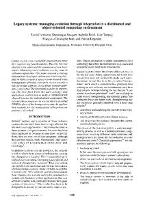
Figure 1: Di�erence between the Local and Remote Procedure Calls 3
Figure 1 illustrates the di�erence between local and remote procedure calls [3]. RPC uses a request-and-reply communication model. The client program sends a request message to the server procedure (process); the server sends back the reply message. The client and server communicate by means of two stubs, one for the client and one for the server. A stub is a communication interface that implements the RPC protocol and speci es how messages are constructed and exchanged. The stub performs the marshalling of arguments (the process of converting the arguments to a form, that can be transmitted over a network) and unmarshalling (the process of reconstructing the arguments from the marshalled form).
2.1 Developing an RPC Application
Normally an RPC application is developed in two steps as explained below. � �
Specify the protocol (or interface) for the client server communication. Develop the client and server programs.
The rst step, specifying the interface/protocol precisely states the interface of the procedure, i.e. it states the procedure name, type and the number of input arguments and the type and number of the output arguments (returned results). Normally a vendor provides a standard speci cation language for specifying this information. Generally these speci cation languages are referred to as IDL (interface de nition language) or RPCL (RPC language). The vendor also provides compilers to compile these interfaces. The compilers generate the necessary stub and header les. The second step involves the development of client and server programs. This is nothing but implementing the application logic. The client and server code should be compiled and linked with the respective stub les to get the client and server load modules. Although RPC programming is conceptually the same on di�erent vendor supplied platforms, syntactically and semantically they are not the same. Below we will explain RPC programming in two common platforms (ONC and DCE).
2.2 ONC RPC Programming
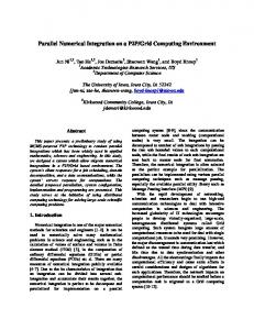
In the ONC environment, the interface (or protocol) is speci ed in the XDR (eXternal Data Representation) language. The detailed description of XDR is given in [3]. The protocol compiler is called RPCGEN. Figure 2 shows the general (normal) steps involved in the application development with RPCGEN [3]. It also shows the various conventions that are generally used. Note that in the ONC environment, an RPC application can be developed without the use of RPCGEN 4
appl.x (*) (Source Protocol Definition)
% rpcgen appl.x
appl_clnt.c Client Stub
appl.h
appl_xdr.c
Includes
appl.c (*)
Data Repersentation Server Stub
Compile & Link
Compile & Link
Application Source RPC Client
appl_svc.c
appl_svc_ proc.c (*) Server Process Source
appl
appl_svc
RPC Server
(*) Code Written by the Developer
Figure 2: Steps involved in developing an ONC RPC application and a Protocol speci cation. In fact it is possible to develop an RPC application with various levels of details [3]. But in this paper and for the tool only ONC RPC programming using RPCGEN is considered.
2.3 DCE RPC Programming
DCE RPC programming is slightly more involved than ONC RPC programming. This is because DCE provides more services to a distributed application developer. Following are the services provided by the DCE. � DCE Threads � DCE Remote Procedure Calls � DCE Directory Service � DCE Distributed Time Service � DCE Security Service 5
DCE Distributed File Service An application developer can use one or more of the above services to develop an application. Since the objective of this project is the conversion of applications from the ONC RPC platform to the DCE RPC platform, only DCE RPC programming is explained here. For a detailed description of programming in DCE see [1, 2, 6, 7]. �
The rst step is to write an interface. In case of DCE, the interface speci cation language is called IDL(Interface De nition Language) and the compiler is idl compiler. In DCE each interface is uniquely identi ed(in time and space) by a UUID( Universal Unique Identi er). This UUID is registered in the Name/Directory service along with the interface name. This UUID (in this context also known as Interface UUID) is used by the client to locate a server in the network.The DCE provides a utility called uuidgen to generate UUIDs.
uuidgen
.idl file (*)
IDL Compiler
Client Stub
Client Src (*)
Header File
Compile & Link
Server Stub
Compile & Link
Server
Client
Server Src(*) Server Manager (*)
(*) Code Written by Developer
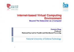
Figure 3: Steps Involved in Developing a DCE RPC Application After writing the interface (the UUID needed by the interface is generated by uuidgen), the client and server programs (application logic) should be developed. Thus, apart from 6
the syntactic(and some semantic) di�erences, the program development procedure in DCE RPC and ONC RPC are similar. In DCE it is also necessary to develop a manager program for the server component. The manager program registers the server in the name space. Note that this program is not present in case of ONC RPC (this functionality is taken care by RPCGEN in stub le). The idl compiler generates the required stub and header les. Figure 3 shows the development process and conventions involved in DCE RPC programming.
3 Porting Tool Overview The goal of the Porting Tool is to automatically convert ONC RPC programs into DCE RPC programs. In doing so, the manual intervention should be minimal. This project only targeted converting the ONC RPC source code which includes the interface de nition source (the .x le) and application logic (client and server - .c les). Conversion of Make les is not attempted. How ever given a standard template, the e�ort required in writing a new make le is minimal.
3.1 Design Overview
While designing such a Porting Tool the following factors should be considered: � � �
The syntax di�erence between ONC RPCL (RPC Language) and DCE IDL. The semantic di�erence between the similar language constructs on the two platforms. The service facilities provided by one that is not supported by the other and vice versa.
Only the syntax and semantic di�erence between the interface/protocol de nition languages in considered here. It is assumed that the source (application logic) is written in `C' language and both platforms support `C'. It is also assumed that the application is working correctly on the ONC platform (as speci ed in the application requirement). The design of the Porting Tool involves mainly the design of the following two sub components(modules). � The design of a conversion module that converts the ONC interface de nition le (the .x le) to the DCE interface le (the .idl le). This module will be called as the X2IDL module. � The design of a conversion module, that converts ONC application programs (client and server programs - .c les) into corresponding DCE application programs (.c les in DCE). This module will be called as the Function Converter module. The following subsections discuss the design of these modules. 7
3.1.1 Design of the X2IDL Module
The following logical steps are involved in the design of the X2IDL module. � � � � � �
Study the grammar of ONC RPCL and DCE IDL. Identify the language constructs in ONC RPCL that can be one-to-one mapped to the language constructs of DCE IDL (with similar syntax but with di�erent keywords). Identify the language constructs in ONC RPCL that can be mapped to similar language constructs in DCE IDL but with di�erent syntax and di�erent keywords. Identify the language constructs in ONC RPCL that can be safely omitted when porting to DCE IDL. Identify the language constructs that are to be added to the .idl le that are (or equivalent of which) not present in ONC RPCL. Identify that part of the code, that may need re-organization (restructuring) when porting to DCE.
In the following, some of the ndings of the above analysis are discussed. A detailed discussion of the ndings is outside the scope of this paper. Interested readers can refer to the SDD(System Design Document) for the DCE Porting Tool [5]. Interested readers can also refer to the grammars of ONC RPCL and DCE IDL in [3, 6]. For brevity the grammars are not presented here. However an example of the ONC RPCL interface le ( the .x le) and the converted(ported) DCE IDL interface le (the .idl le) is given in appendix A. This will illustrate most of the points discussed here. A new construct that is to be added to DCE IDL is the addition of UUID along with the interface name. The interface name is derived from the `.x' program name (the `.x' le is the protocol de nition le in ONC RPCL and program name is the name given for the interface). The (interface) UUID is generated using uuidgen. The \version number" is mapped one-to-one. Note that in case of the .idl the interface name and the version number appear at the beginning of the source le. But in the case of the .x le it appears at the end of le. Because of this the conversion task is carried out as a two pass process (more about the implementation detail is given in the next section). Following are some of the mapping decisions made in the design. � string type in the .x le is converted to char pointer (char *) in the .idl le. � int type in the .x le is converted to long int in the .idl le. This is because IDL does not support an int type. 8
�
� � �
�
�
struct type of the .x le is converted to struct type of the .idl le. Here it is necessary to add some additional keywords to the struct construct of the .idl le so that it retains
the same meaning in the .idl le as in the .x le. All of the structure members are converted accordingly. discriminated union type of the .x le is converted to a similar structure in the .idl le but with di�erent syntax. The procedure numbers in the .x le are omitted in the .idl le. IDL does not have procedure numbers. The procedure has only one parameter in the .x le (basically the input parameter to the procedure). In the .idl le one more parameter is added to the procedure. The added parameter is the binding handler parameter. Binding handler [2] is used by DCE RPC call when explicit binding method is used. In the converted DCE RPC program, explicit binding method (to retain the same semantic of ONC RPC call) is used. Some constructs of RPCL (the .x le) are not supported in IDL. RPCGEN also acts as a preprocessor for the .x le. It puts some constructs like macro de nitions in an include le (similar to .h le in `C'). Examples are CONST de nitions and some conditional compilation statements. While porting to DCE, such statements are written as macro de nitions (# de ne's in \C") in a special le named as xxxx M.h (where xxxx is the le name of the .x le without .x). This le will be included in all the ported source les (the client, server and the manager les). A le, xxxx svc DCE.c (where xxxx is the same as above) is generated during the conversion process. This le contains the code for registering the DCE RPC interface with the Name Service and DCE runtime. Later we will give more details about this le.
3.1.2 Design of Function Converter Module
For the conversion of source les (.c les) a di�erent approach is taken. Since the same language syntax and semantics are used in both the environments (ONC RPC and DCE RPC), there is no need for any syntactic changes while converting application source (logic) les from ONC environment to DCE (the programming language 'C' is used in both the environments). However, in ONC RPC environment the .c les contain the function calls that are supported and meaningful only in ONC. Many of these functions are not supported in DCE(or not necessary in DCE). The main design tasks in the conversion of source les are the following. �
Identify the ONC function calls that can be directly mapped with the same semantics to DCE function calls. 9
� �
�
Identify the ONC function calls that have similar (may be with slightly di�erent semantics) DCE function calls. Identify the ONC functions that have no equivalent DCE function calls. For some of these functions it is necessary to develop equivalents, but some of these functions can be safely omitted. Identify ONC speci c \#include les" and replace them with DCE speci c \#include les".
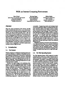
A detailed discussion of the result of the above study is given in the appendices of SDD (System Design Document) [5]. Some of the salient design decisions are discussed here. In the converted application the explicit binding method of the DCE RPC is used. This is because in ONC RPC, the client knows the server location and directs the RPC call to a speci c server. We wanted to retain this feature of the original program in the DCE environment also. For this purpose the clnt create() function of ONC RPC is replaced by a new function called DCE clnt create(). This new function will search the DCE Name Space (cell directory) and will obtain the (explicit) binding handle. This binding handle is used as the rst parameter in all the RPC calls. Note that all of the ONC RPC calls are converted to DCE RPC calls just by including this binding handle. The xxxx M.h header le has the required macros to e�ect this change. Also all ONC speci c function calls (not ONC RPC calls) are pre xed by 'DCE ' (for example, onc function() is replaced by DCE onc function()). A separate le called map.c implements all these functions with the necessary logic. The map.o le is linked with respective .o les of server and client. Also in DCE it is necessary to register the server in the DCE name space (DCE Cell Directory Service) and with the DCE runtime (Note that even in case of ONC it is necessary to register the server with the ONC runtime, called portmapper. But this is done by the stub les transparently when the .x le and RPCGEN are used in the application development). To implement this functionality a separate le ( with le name xxxx svc DCE.c) is generated during the conversion process (as mentioned before). The code in this le implements the logic for registering the server in the DCE name space and DCE runtime. The content of this le is more or less the same for any RPC program. Only changes are the interface related names and these names are obtained from the .x le. Figure 4 illustrates the conversion process from ONC RPC using the Porting Tool.
3.2 Implementation Overview
The implementation involves analyzing the syntax (and recognizing the language tokens) for the .x le (ONC RPCL). It is also necessary to parse the .x le, so that the logically equivalent .idl le can be generated. This is something similar to interpreting the .x le. Language processing tools LEX and YACC being ideal for such a job. Thus LEX and YACC [4] are used in the implementation of the Porting Tool. The implementation of the Porting Tool contains three main modules. 10
ONC Application (Already Running on ONC platform) .x file (ONC)
Client Src (ONC)
Server Src (ONC)
Manual Conversion
DCE PORTING TOOL
map.o
.idl (DCE)
ONC Makefile
Client Src Server Src (DCE) (DCE)
Compile & Link (In DCE patform)
DCE Client
DCE Server
Figure 4: Expected Usage of the DCE Porting Tool
X2IDL This module converts the ONC RPC .x le into DCE RPC .idl le. This module also generates M.h(macro header le) and svc DCE.c(Server registration logic) les. The logic of this module is implemented using LEX and YACC. Function Converter This module converts the source les (.c les - both client and server source les) of ONC RPC application into the source les of DCE RPC application. The logic of this module is implemented using LEX. GUI - Graphical User Interface This module is responsible for presenting the Porting Tool to the user in a friendly manner. It has the necessary pull down menus and data entry windows. It is developed using OSF/MOTIF according to the suggested style [8, 9, 10]. Figure 5 shows a high level block diagram of the modules in the Porting Tool.
11
.x file _M.h file
X2IDL
.idl file
G _svc file U
svc.template
I Function Converter
.c files (DCE)
.c files (ONC)
Figure 5: Overview of the Porting Tool
4 Implementation Details In this section some of the salient features of the implementation is discussed. It is assumed that the reader is familiar with language processing concepts such as context free grammars, lexical analysis, parsing and tools like LEX and YACC.
4.1 Implementation of X2IDL Module
The X2IDL module converts a .x le into to a .idl le. As explained in the design overview, the X2IDL module needs to generate two additional les other than .idl le. Figure 6 shows the block diagram of the X2IDL module. It also shows the sub modules of the X2IDL. The X2IDL module takes two input les and produces three output les. The input les are: .x le : This is the ONC RPC interface de nition le. 12
.x file
svc.template file
X2IDL Module
.x Grammar PASS1 LEX ( x2idl.lex.l )
YACC ( x2idl.yac.y )
Parser (Intermediate Files)
LEX ( x2idl.lex.l )
PASS2
.idl file
_M.h file
_svc_DCE.c
Figure 6: Block Diagram of X2IDL module
svc.template le : This le contains the standard code for registering the interface with
the DCE name service and DCE runtime. This le has some place-holder variable names. These variable names are replaced by appropriate interface related names, extracted from the .x le. The output les of the module are: .idl le : This is the converted .x le. It is the interface le for the DCE RPC. M.h le : This is the macro (header) le. The contents of this le comes from the .x le. It contains .x le statements that do not have .idl equivalents. The rationale for this le was explained before. It also contains macro de nitions that will change the structure of ONC RPC calls so that now they work in DCE. It also contains some other miscellaneous de nitions. For details see SDD [5]. svc DCE.c le : This le is the svc.template le with the proper interface related variable names substituted. The X2IDL module has two major sub modules called pass1 and pass2. In e�ect these two modules make two passes on the .x le. It is necessary to have two passes for the following 13
reason. The program-name in the .x le is available some where at the middle of the the .x le and it is needed for deriving the interface name for the .idl le. In .idl le interface name appears near the beginning of the le. For details refer to SDD [5]. Module pass1 is the parser for X2IDL. It uses .x grammar (ONC RPCL grammar) to parse the .x le. The parser is implemented using YACC. The parser calls the LEXER for getting the tokens from the .x le. The logic of this module is straight forward. When it can reduce a set of tokens (according to the grammar) it outputs a string to the intermediate le(s). This string may contain the actual .idl statement or place-holder variables which will be substituted in the second pass through these intermediate les. The content of the output string depends on the input tokens read and the conversion speci cations identi ed in the design stage. This module also stores some values in the global variables. These global variables are used by the pass2 module (eg. .x program-name). Module pass2 creates the output les. It reads the intermediate les created by pass1 module and substitutes the place-holder variable names with the appropriate values (that are stored in the global variables by pass1 module) and writes the complete output les. It also reads the svc.template le and lls out the interface related names and writes out svc DCE.c le. Module pass2 is implemented using LEX. All this module needs to do is to identify the place-holder variable strings in the intermediate les and substitute them by the correct values. It need not understand the syntax of the input les. Thus the LEXER is enough to do the job. In the implementation, the same LEXER code is used for pass1 and pass2. Of course di�erent lexer states are used in the two passes. Details are given in SDD [5].
4.2 Implementation of Function Converter The implementation of function conversion module (function converter) is quite straight forward. As identi ed in the design stage (section 3), the function converter has to do the following for each of the source les(.c les). � � �
Replace ONC RPC speci c #include(header) les by DCE speci c header les. Include xxxx M.h macro(header) le in the converted source le. Pre x all ONC function calls onc function() by DCE (i.e. it becomes DCE onc function().
From the above requirement, it can be observed that the function converter only need to recognize the language tokens. Thus only LEX is su�cient for implementing the function converter. Figure 7 shows a block diagram of the function converter. Note that the function converter takes two input les. The aaa.x le (the .x le) is needed just to derive the name of the 14
aaa.x file Function Converter ( LEXER ) bbb.c file
bbb_DCE.c file (Converted DCE file)
( ONC file )
Figure 7: Block Diagram of Function Converter Module
M.h macro le. This macro le is to be included in the converted source le ( DCE.c le). The function converter module, has a look up table. The table entries are of the form [onc function, status]. The status is a character variable that can take a value of either \y" or \n". This basically means that the respective onc function has a corresponding DCE function (or equivalent DCE function has been implemented). Figure 8 shows the logic ow of the function converter module. Note that there are only a couple of ONC speci c header les (eg. ). So these le names are hard coded in the program. Also at the beginning of the output le, a statement to include the generated macro le is written out ( #include \xxxx M.h").
4.3 Implementation of GUI
The GUI (Graphical User Interface) provides a user friendly environment, to use the Porting Tool. GUI is developed using OSF/MOTIF in accordance with the suggested style [8, 9, 10]. It provides convenient pull down menus, text entry elds and le browse windows for the easy access of Porting Tool components. The implementation logic of GUI follows the eventdriven programming model that is generally used in the case of Motif/X Window system programming. The details are omitted here. The GUI provides the following facilities to the user. � General interface for the user to select le(s) ( le browser). � Interface to invoke X2IDL and Function Converter modules. � A facility to store the current selection of le name(s) in a .prj le. This .prj le can be reloaded later. This saves some keystrokes. � Displays the statistics of the conversion process (the les involved and the number of lines of code etc.). 15
Initialize
EOF
Read Next Token
STOP
Is it an ONC include file No Yes Is it an ONC Function
Replace by DCE file
Yes
Search Table
No Write token Inform the User Prefix token by DCE_ write token
No
Correspnding DCE function Implemted
Yes
Figure 8: The Logic Flow of Function Converter Module
5 Summary and Limitations This paper brie y described the design and implementation of DCE Porting Tool. The objective of the project was to convert ONC RPC programs to DCE RPC programs automatically. The current implementation of the tool on an IBM AIX platform works as per expectations. However the tool has some limitations. The tool works only if the ONC RPC application was developed using RPCGEN (i.e., with the .x le). As noted before, an ONC RPC program can be developed without using the .x le. In this case the tool cannot be used. Also even while using RPCGEN, one can use low-level ONC function calls (like call rpc()) which cannot be easily mapped to an equivalent DCE call. This is because, in DCE it is assumed that all applications will be developed using IDL (the .idl le). Also while converting the ONC programs to DCE, the new facilities provided by DCE (like name service) are not e�ectively used. We just wanted to run the 16
ONC RPC applications in DCE without re-writing the application. We did not consider changing the application logic for taking the advantage of DCE services. The make les are not converted either. However this is not a serious limitation. The future work will concentrate on removing some of the above limitations.
Acknowledgment: The authors would like to express their appreciation to Mr. Scott Page at IBM Austin for his valuable comments throughout this project.
17
References [1] H. W. Lockhart, \OSF DCE, Guide to Developing Distributed Applications," McGraw Hill, Inc., 1994. [2] John Shirly, \Guide to Writing DCE Applications," O'Reilly & Associates, Inc., Sebastopol, CA 1993. [3] J. Bloomer, \Power Programming with RPC," O'Reilly & Associates, Inc., Sebastopol, CA 1992. [4] J. R. Levine, J. Mason, D. Brown, \LEX & YACC," O'Reilly & Associates, Inc., Sebastopol, CA 1992. [5] System Design Document for DCE Porting Tool, Prepared for IBM Austin, Contract No. 32525-42640-CS, Texas A&M University, 1994. [6] OSF, \OSF DCE Application Development Reference," Prentice Hall, New Jersey, 1991. [7] OSF, \OSF DCE User's Guide and Reference," Prentice Hall, New Jersey, 1991. [8] OSF, \OSF/MOTIF Programmers Guide," Prentice Hall, New Jersey, 1990. [9] OSF, \OSF/MOTIF Programmers Reference," Prentice Hall, New Jersey, 1990. [10] OSF, \OSF/MOTIF Style Guide," Prentice Hall, New Jersey, 1990.
18
Appendix A The following code is an example of ONC RPC .x le(interface speci cation for ONC RPC). /* * rdb.x: remote database access protocol */ /* preprocessor directives */ %#define DATABASE "personnel.dat" /* '%' passes it through */ /* constant definitions */ const MAX_STR = 256; /* structure definitions, no enumerations needed */ struct record { string firstName; /* defines the maximum */ string middleInitial; /* possible length */ string lastName; int phone; string location; }; /* program definition, no union or typdef definitions needed */ program RDBPROG { /* could manage multiple servers */ version RDBVERS { record FIRSTNAME_KEY(string) = 1; record LASTNAME_KEY(string) = 2; record PHONE_KEY(int) = 3; record LOCATION_KEY(string) = 4; int ADD_RECORD(record) = 5; } = 1; } = 0x20000001; /* program number ranges established by ONC */
19
The following code is an example of converted ONC RPC .x le. The converted le is .idl le(interface speci cation for DCE RPC). [ /* Program Name RDBPROG and ID 0x20000001 */ uuid(002aa21a-8d1a-1e0c-9a0b-80c28e3eaa77), version(1) /* version name RDBVERS*/ ] interface ONC_RDBPROG {/* * rdb.x: remote database access protocol */ /* preprocessor directives */ /* constant definitions */ /* structure definitions, no enumerations needed */ typedef struct record { [string, ptr] char * firstName ; /* defines the maximum */ [string, ptr] char * middleInitial ; /* possible length */ [string, ptr] char * lastName ; long phone; [string, ptr] char * location ; } record ; /* program definition, no union or typdef definitions needed */ /* could manage multiple servers */ /* function 1 */ [idempotent] record * firstname_key_1([in] handle_t cl, [in] char * arg); /* function 2 */ [idempotent] record * lastname_key_1([in] handle_t cl, [in] char * arg); /* function 3 */ [idempotent] record * phone_key_1([in] handle_t cl, [in] long * arg); /* function 4 */ [idempotent] record * location_key_1([in] handle_t cl, [in] char * arg); /* function 5 */ [idempotent] long * add_record_1([in] handle_t cl, [in] record * arg); /* program number ranges established by ONC */ }
20