problem in millimeter-wave (mmWave) communication, each with its own .... ated with simulations and compared with several benchmark schemes, where ...
Dealing with Link Blockage in mmWave Networks: D2D Relaying or Multi-beam Reflection? Mingjie Feng, Shiwen Mao
Tao Jiang
Dept. Electrical & Computer Engineering Auburn University, Auburn, AL 36849-5201, U.S.A.
School of Electronic Information & Communications Huazhong Univ. Science & Technology, Wuhan 430074 China
Abstract—Device to device (D2D) relaying and multi-beam reflection are two effective approaches to deal with the blockage problem in millimeter-wave (mmWave) communication, each with its own limitations when serving a large number of user equipments (UE). A combination of D2D relaying and multibeam reflection is expected to enhance the performance, but the selection of UEs to be served by each approache remains a challenge. In this paper, we consider adaptive mode selection between D2D relaying and multi-beam reflection in a time division duplex (TDD) mmWave network. We formulate a joint mode selection and resource sharing problem with the objective of maximizing the sum logarithm rate, and propose a two-stage solution algorithm. In the first stage, we derive the optimal resource sharing solution under the case that all UEs are served by D2D relaying. In the second stage, an adaptive algorithm is proposed to determine the set of UEs that switch from D2D relaying to multi-beam reflection. Simulation results demonstrate that the proposed scheme achieves considerable performance gain compared to several benchmark schemes.
I. I NTRODUCTION With the growing popularity of data-intensive applications, the next generation (i.e., 5G) wireless network is expected to provide 1000x data rate [1]. Millimeter-wave (mmWave) communication is one of the key enabling technologies of 5G wireless to meet such challenges [2], [3], along with massive MIMO [4] and small cells [5], [6]. Operating in the higher end of spectrum ranging from 30GHz to 300GHz, a large bandwidth is available (e.g., a 7 GHz license-free spectrum between 57 GHz and 64 GHz was approved by FCC), resulting in significantly improved data rate. Despite such great potential, a major challenge of mmWave communications is to overcome blockages. Due to the short wave length, the mmWave cannot penetrate obstacles such as walls and human bodies. Thus, the line-of-sight (LOS) path between a base station (BS) and a user equipment (UE) may be easily blocked due to the mobility of the UE or other UEs. To maintain connectivity, alternative links have to be found and used. To this end, there are three possible approaches, including (i) device to device (D2D) relaying by other UEs, (ii) refection of beams [8], [9], (iii) handover to other BSs. The D2D enabled mmWave network was considered in [10], [11], in which effective MAC protocols were proposed. A multibeam reflection architecture was recently proposed in [12], where the concept of beamspace MIMO was introduced and a multiplexing gain was achieved. In [13], an inter-BS coordinac 2017 IEEE 978-1-5386-3531-5/17/$31.00 ⃝
tion mechanism is designed to deal with the NLOS challenge by optimizing the set of BSs serving each UE. Although these solutions are effective in dealing with blockage, the performance gain is limited by some inherent factors of these approaches. For D2D relaying, a relaying UE must share part of its resource with other UEs. Besides, multihop relaying increases the delay since the packets have to be forwarded multiple times. The major challenge of multibeam reflection is the large path loss exponent of NLOS links. Compared to LOS links with a typical path loss exponent of 2, the path loss exponent of NLOS can be as large as 4 [14]. Hence, only a certain set of UEs are suitable for multibeam reflection. In addition, in case of serving a large number of UEs, the transmission power allocated to each UE would be limited, resulting in degraded quality of service (QoS). The handover approach, which seems easy to implement in traditional cellular network, requires intensive coordination among BSs in an mmWave network. Due to the narrow beam of mmWave transmissions, discovering an alternative BS and tracking roaming UEs may incur additional overhead, such as that caused by beam sweeping [15]. To avoid these drawbacks and fully harness the benefits of these approaches, a combination of multiple approaches with a proper integral design has the potential to enhance the system performance. As the UEs are served by multiple approaches, the number of UEs served by each approach is reduced, the resource allocated to each UE can be increased, resulting in improved performance. Then, how to select the sets of UEs served by different approaches is a key factor that impacts the system performance, but has not been investigated in previous works. In this paper, we consider a combination of D2D relaying and multi-beam reflection with an adaptive selection between the two approaches in a single cell time division duplex (TDD) mmWave network. We formulate a joint mode selection and resource sharing problem with the objective of maximizing the sum logarithm rate, and propose a two-stage solution algorithm. In the first stage, we consider the case that all NLOS UEs are served by D2D relaying, and derive the optimal resource sharing solution. Based on the solution, an adaptive mode selection algorithm is then proposed in the second stage to determine the sets of NLOS UEs served by D2D relaying and multi-beam reflection. The proposed scheme is evaluated with simulations and compared with several benchmark schemes, where considerable performance gains are achieved.
1st hop 2nd hop 3rd hop
(N-1) th hop
4th hop
Downlink period divided into N time slots
N th hop
0
1
2
4
3
5
N-2
N-1
N
1st transmission: 0ĺ1 1,…,N
BS
1ĺ2 2,…,N
2ĺ3 3,…,N
3ĺ4 4,…,N
4ĺ5 5,…,N
N-2ĺN-1 N-1, N
N-1ĺN N
No shared node for concurrent transmissions 2nd transmission:
LOS
NLOS : D2D relaying and BS - LOS UEs
1ĺ2 2,…,N-2
2ĺ3 3,…,N-2
N-4ĺN-3 N-3,N-2
N-3ĺN-2 N-2
3rd transmission:
0ĺ1 1,…,N-4
N-6ĺN-5 N-5,N-4
N-5ĺN-4 N-4
0ĺ1 1,2
1ĺ2 2
0ĺ1 1,…,N-2
: Multi-beam reflection
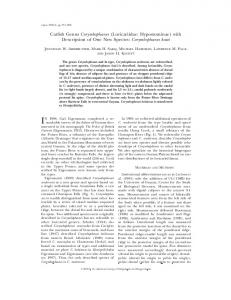
Fig. 1. System model of a D2D and multi-beam enabled multi-hop mmWave cellular network. .
In the remainder of this paper, we present the system model and problem formulation in Section II. The solution algorithm is given in Section III. The simulation results are discussed in Section IV. We conclude this paper in Section V.
If N is an even number:
N/2 th transmission:
If N is an odd number:
(N+1)/2 th transmission:
0ĺ1 1
From i th hop to (i+1) th hop The set of hops with packets transmitted
Fig. 2. Transmission pattern of a TDD-based multi-hop D2D mmWave cellular network.
II. P ROBLEM F ORMULATION We consider an mmWave cellular network that supports directional transmissions with a small beamwidth, e.g., less than 10◦ . Due to the “pseudo-wired” property and large propagation loss, the performance gain achieved from interBS interference coordination is limited. Thus, we focus on link scheduling of one BS and the UEs it serves. Assume the set of UEs served by each BS is predetermined, we focus on a tagged BS serving K UEs indexed by k = 1, 2, . . . , K. The UEs are subject to random blockage and can relay data for other UEs in case of blockage. The blocked UEs are served by either multi-hop D2D relaying or multi-beam reflection. We assume the system operate in the TDD mode, so that channel reciprocity can be exploited for efficient channel estimation. As shown in Fig. 1, we consider link scheduling for downlink transmissions. Each NLOS UE receives its packets from a single relaying UE. Then, the network architecture of multi-hop D2D relaying can be viewed as a tree, while multibeam reflection can be viewed as an alternative (or, augment) connection from the root to a node that corresponds to an NLOS UE. Define xk and yk as indicators for multi-hop D2D relaying and multi-beam reflection for user k, respectively, given as { . 1, user k is served by D2D relaying or LOS link xk = (1) 0, otherwise, . yk =
{
1, user k is served by multi-beam reflection 0, otherwise,
(2)
We assign xk = 1 to LOS UEs since they are part of the D2D relaying architecture. We then use a descendent matrix to indicate the relaying route of each NLOS UEs, defined as { 1, user k ′ is a descendent of user k . ak,k′ = (3) 0, otherwise,
Since ak,k′ is defined for UEs involved in the D2D relaying process, we have ak,k′ ≤ xk and ak,k′ ≤ xk′ . Let ρk be the depth of UE k in the D2D relaying tree, given by ∑ ak′ ,k + 1. (4) ρk = ′ k ̸=k
That is, ρk is also the number of hops required to transmit the packets of UE k. Let N be the maximum value of ρk . To accommodate N -hop D2D relaying and guarantee that the packets of UEs at the N th hop can be delivered at the end of each downlink transmission, we divide the downlink transmission period into N time slots as shown in Fig. 2. Each time slot is used for transmission from UEs in one hop to UEs in the next hop. For a UE served with multi-beam reflection, the entire downlink period is allocated to the UE. We assume that all UEs can only perform half duplex relaying; two adjacent links that share the same UE cannot operate ⌈ ⌉ concurrently [16]. Under this constraint, a total number of N2 transmissions can be implemented, as shown in Fig. 2. For example, after the 2nd stage of the 1st transmission, which is from UEs with ρk = 1 to UEs with ρk = 2, the 2nd transmission can be initiated since UEs with ρk = 1 have finished transmission and are free for reception. Note that, as the index of transmissions increases, the packets of UEs with larger ρk are not contained since there is no enough time for the transmissions of these UEs. In particular, the packets of UEs with ρk = N − 1 and ρk = N are not contained in the 2nd transmission, the packets of UEs with ρk = N − 3, ..., N are not contained in the 3rd transmission, and so on. Then, the total number of transmissions for UE k, θk , is given by { N ⌈ ρk ⌉ 2 − 2⌊ + ⌋ 1, N is even (5) θk = ρk N +1 − N is odd, 2 2 , The BS is able to serve multiple users on the same timefrequency resource block with advanced techniques, such as
hybrid beamforming [7]. Due to hardware constraints, when a UE relays the packets of multiple UEs, resource sharing is required among these UEs. Without loss of generality, we assume time division multiple access (TDMA) is applied when a UE forwards the packets to multiple UEs. Specifically, a fraction of time in each time slot is allocated to each D2D link between the relaying UE and a UE at the next hop. We define ti,j k as the fraction of time allocated to UE k on its ith hop during the jth transmission. From the perspective of outflow, ti,j k should satisfy ⌈ρ ⌉ ∑ k ak,k′ tρkk′+1,j ≤1, k∈{k|ρk ≤N−1 }, j=1, ..., θk + .(6) 2 ′ k ̸=k
For UEs with ρk = 1, i.e., the LOS UEs, the inflow constraint is given as ⌈ ⌉ ∑ N 1,j 1,j ak,k′ tk′ +tk ≤1, k ∈{k |ρk =1 }, j =1, ..., . (7) 2 ′ k ̸=k
The inflow constraint (7) is only required for the 1st hop transmission, since the inflow of other hops would only be part of a time slot due to TDMA at the previous hop; the left-hand side of (7) would always be no larger than 1. In a multi-hop transmission, the data rate of a link at the current hop should be no less than the data rate of the link at the next hop. Thus, {ti,j k } should also satisfy i+1 i+1,j Cki ti,j , k ∈{k |ρk ≥2 }, i=1, ..., ρk −1, k ≥Ck tk
where
Cki
(8)
UEs. Similar to (10), the SINR of an LOS UE is given by −2
p˜k h1k G1k (d1k ) . (12) σ2 Suppose UE k is served with the reflection of Mk beams indexed by m = 1, ..., Mk . Let γ˜km be the SINR of the path corresponding to the m th beam of UE k, given as γk1 =
−4
m m m p˜m k hk Gk (dk ) , (13) σ2 m m m where p˜m k , hk , Gk , and dk are the power, small-scale fading, antenna array gain, and distance of the mth path, respectively. We neglect the interference caused by side lobes. Without loss of generality, we assume p˜k is equally allocated to the Mk beams. The path loss factor for NLOS reflection is 4. For UE k served by multi-hop D2D relaying, its downlink data rate is the sum of all θk transmissions. In each multi-hop transmission, the effective data rate is determined by data rate of the final hop divided by the number of hops. Then, the data rate of UE k when served by multi-hop D2D relaying in the downlink period is given by
γ˜km =
Rk =
Next, we derive the SINR expressions under different transmission schemes, employing the baseline SINR model presented in [14]. For UEs served by D2D relaying, we have γki =
−2 pik hik Gik (dik ) , σ2
(10)
where hik is the small scale fading, which is a normalized Gamma random variable [14]; Gik is antenna array gain; dik is the distance of the link; and pik is the transmission power of the BS or UE for the ith hop of UE k. The noise power is σ 2 , and we neglect the impact of interference. In (10), we assume that the LOS path loss exponent is 2. For UEs served by BS with multi-beam reflection and UEs served by BS with an LOS link, we assume the power of BS is equally allocated to these UEs. Then, the transmission power allocated to each UE is P0 p˜k = ∑ , (11) y k k + NLOS where P0 is the BS power and NLOS is the number of LOS
k
k
ρk
j=1
.
(14)
The data rate of LOS UEs is a special case of (14) with ρk = 1. When UE k is served by multi-beam reflection in the downlink period, its data rate is given by
is the link capacity of hop i of UE k, given by ) ( (9) Cki = B log 1 + γki ,
where B is the system bandwidth and γki is the SINR of hop i of UE k. Here, the SINR is constant over all θk transmissions, since the duration of uplink and downlink periods is less than the coherence interval in a TDD system.
θk ∑ C ρk tρk ,j
˜k = R
Mk ∑
B log (1 + γ˜km ).
(15)
m=1
In this paper, we aim to maximize the logarithm rate sum of all UEs with adaptive selection between D2D relaying and multi-beam reflection for all NLOS UEs. Let x, y, a, and t be the vector/matrix forms of {xk }, {yk }, {ak,k′ }, and {ti,j k }. The problem is formulated as } {K K ∑ ∑ ˜ xk log Rk + yk log Rk (16) P1: max {x,y,a,t}
k=1
k=1
subject to: xk + yk ≤ 1, ∀k (17) ⌈ρ ⌉ ∑ k ρk+1,j ak,k′ tk′ ≤1, k∈{k|ρk ≤N−1 }, j=1, ..., θk + (18) 2 k′ ̸=k ⌈ ⌉ ∑ N 1,j (19) ak,k′ t1,j +t ≤1, k ∈{k |ρ =1 }, j =1, ..., k k′ k 2 ′ k ̸=k
Cki−1 ti−1,j ≥ Cki ti,j k , k ∈ {k |ρk ≥ 2 }, i = 1, ..., ρk ∑ k ak′ ,k ≤ 1, k ∈ {k |ρk ≤ 2 }, ′
(20)
ak,k′ ≤ xk , ∀k.
(22)
ti,j k
(23) (24)
k ̸=k
ti,j k
≤ xk , 0 ≤ ≤ 1, ∀k, i, j. xk , yk , ak,k′ ∈ {0, 1} , ∀k.
(21)
Constraint (20) is due to the fact that each node in the D2D relaying tree can only have one parent node.
III. S OLUTION A LGORITHM
Algorithm 1: Adaptive Mode Selection Algorithm
Problem P1 is a mixed integer programming problem with multiple sets of variables, which cannot be solved with standard techniques. To derive an effective solution, we propose a two-stage algorithm for adaptive selection between D2D relaying and multi-beam reflection. In the first stage, we consider the case that all NLOS UEs are served with D2D relaying and derive the optimal resource allocation solution. Based on the solution, the UEs that can be served by multibeam reflection are evaluated in the second stage, then the set of UEs to be served by multi-beam is determined. A. First Stage We assume that path selection for D2D relaying is predetermined with a routing approach, e.g., adopting Dijkstra’s Algorithm by setting the weight of each link as the inverse of its channel gain [17]. With all NLOS UEs served by D2D relaying, problem P1 is reduced to the following resource allocation problem. θk K ρk ρk ,j ∑ ∑ C t k k P2: max log (25) ρk {t} j=1 k=1
subject to: (18) − (20)
B. Second Stage Based on the optimal solution of problem P2, we then evaluate the performance gain of switching a UE from D2D to multi-beam, and determine the set of UEs to be served [τ ] with multi-beam reflection. We define ∆k as the performance gain of all UEs by selecting UE k to switch from D2D relaying to multi-beam reflection at the τ th round. For a UE with descendent UE(s) in the D2D tree, we assume that all of its descendent UEs would also switch to multibeam reflection since re-constructing the D2D tree is timeconsuming, which should not be carried out frequently. Then, [τ ] ˜ [τ ] − log R[τ ] + the performance gain is given )as: ∆k = log R k k ( ∑ [τ ] [τ ] ˜ ′ − log R ′ . ak,k′ log R k k
Since the objective arithm rate, the value among different UEs. from D2D relaying to
function is to maximize the sum logof tρkk ,j would be close to each other Thus, when an NLOS UE l switches multi-beam reflection, we approximate
the values of tρkk ,j of other UEs to be increased by ρ ,j
tl l +
∑ ρ ′ ,j l l′ ̸=l al,l′ tl′ ∑ , k xk
3 4 5 6 7
8
9 10 11 12 13 14 15
16
17 18 19 20 21 22
It can be verified that problem P2 is a convex optimization problem and strong duality holds. The Lagrangian dual method can be applied to obtain the optimal solution.
k′ ̸=k
1 2
ρ ,j
t l ∑l k
xk
or depending on whether UE l has any descendent in the D2D tree. Since we assume equal power allocation, the transmission power allocated to each LOS UE ∑ and multi-beam NLOS ∑ UE is decreased by a factor of y +NLOS yk +NLOS k∑ ∑ k k ∑ or , depending on k yk +1+NLOS k yk +1+ l′ ̸=l al,l′ +NLOS whether UE l has any descendent in the D2D tree. Let ηk = { k ′ | ak,k′ = 1} and Φ be the set of UEs served by D2D relaying. The adaptive algorithm for selection between
Initialize: xk = 1, yk = 0, ∀k, Φ = {1, ..., K} ; [1] τ = 1, l[1] = arg max{k|xk =1} ∆k ; [τ ] while ∆l > 0 do if ρl = 1 then Set yl = 1, xl = 0, Φ = Φ − {l} ; for k = 1 : K do [τ ] ρ ,j ∑ Update Rk′ with (14) by adding tl l / k xk to ρk ,j each tk , k ∈ Φ ; ˜ [τ ] with (15) by multiplying p˜k by Update R ∑ k ∑ ( k yk + NLOS )/( k yk + 1 + NLOS ); [τ ] Calculate ∆k ; end else Set yl = 1, xl = 0; yl′ = 1, x′l = 0, for l′ ∈ ηl ; Φ = Φ − {l} − ηl ; for k = 1 : K do [τ ] Update Rk′ with (14) by adding ∑ ∑ ρ ′ ,j ρ ,j ρl ,j (tl + l′ ̸=l al,l′ tl′l )/ k xk to each tkk , k ∈ Φ; ˜ [τ ] with (15) by multiplying Update R ∑ k ∑ ∑ ( k yk +NLOS )/( k yk +1+ l′ ̸=l al,l′ +NLOS ) m / Φ; to each p˜k , k ∈ [τ ] Calculate ∆k ; end end [τ ] [τ ] l = arg max{k∈Φ} ∆k ; τ =τ +1 ; end
D2D and multi-beam is summarized in Algorithm 1. In each round of Algorithm 1, the UE or the set of UEs that brings the largest performance gain is selected to switch from D2D relaying to multi-beam reflection. Such process terminates until no positive gain can be achieved. IV. S IMULATION S TUDY We validate the performance of the proposed scheme through MATLAB simulations. We consider one BS serving multiple UEs with coverage range of 50 m. The system bandwidth is 1 GHz. The UEs are randomly distributed in the coverage area. Each UE is subject to random blockage with probability Pkb . We assume that the blockage probability is proportional to the distance between the UE and the BS with coefficient κ, given as Pkb = min {κ · Dk , 1}. As an example, when κ = 0.04, a UE that is 10 m away from the BS has a probability of 0.4 to be blocked; for UEs that are more than 25 m away, they are always blocked. We compare with a heuristic scheme. In each round of the heuristic scheme, the UE with the ˜ k is selected to be served with multi-beam largest value of R ∑ ˜ k decreases. reflection. Such process terminates until k yk R We also consider the case of setting the objective function of Problem P2 as sum rate maximization, which serves as an upper bound for the sum rate performance. Fig. 3 shows the sum rate performance under different number of UEs. The sum rate of the multi-beam only scheme is lower than other schemes due to the large path loss exponent of NLOS links and the increased transmission distance brought by reflection. The D2D only scheme achieves higher sum rate than the multi-beam only scheme, but its performance is
10
4
10
x 10
7
x 10
1
Proposed Heuristic D2D only Multi−beam only Upper bound
3.5 6
2.5
2
1.5
0.5
0
5
4
3
0.7
0.6
0.5
0.4
0.3
2
Proposed Heuristic D2D only Multi−beam only Upper bound
1
0.8
Fairness index
5
Average sum rate (bps)
Average sum rate (bps)
3
0.9
0.2 1
Sum logarithm rate maximization Sum rate maximization
0.1
10
15
20
Number of UEs
Fig. 3. Average sum rate under different numbers of UEs. κ = 0.02.
0 0.01
0.015
0.02
0.025
0.03
0.035
Blockage coefficient κ
0.04
0.045
0.05
0
5
10
15
20
Number of UEs
Fig. 4. Average sum rate under different values Fig. 5. Fairness with different objective functions. of κ. The number of UEs is 15. The number of UEs is 15 and κ = 0.02.
significantly degraded when the number of UEs is large. The degraded performance of D2D only scheme results from both resource sharing among UEs and the increased time spent on multi-hop transmission. By selecting some UEs to be served by multi-beam reflection, the heuristic scheme and the proposed scheme achieve better performance, due to the reduced number of UEs involved in D2D transmission. The proposed scheme outperforms the heuristic scheme since the proposed adaptive algorithm jointly considers the performances of UEs served by D2D and multi-beam, while the heuristic scheme is only based on UEs served by multi-beam. The performance of the proposed scheme is close to its upper bound, showing that the performance loss due to fairness concern is relatively small. The results of Fig. 3 indicate that both D2D relaying and multibeam reflection are highly limited by the increasing traffic. A combination of the two approaches with proper UE selection can effectively improve the system performance. The performances under different blockage coefficients, κ, is shown in Fig. 4. As κ increases, the performances of all schemes are degraded due to increased ratio of NLOS UEs. It can be seen that the performance of both D2D only and multibeam only schemes are highly sensitive to blockage, since the time and power resources are shared by the increasing number of NLOS UEs. With adaptive selection between D2D and multi-beam, the proposed scheme achieves considerable performance gain, especially when κ is large. Fig. 5 shows the fairness performance by setting different objective functions for Problem P2. We use the Jain’s fairness ∑ ∑ ˜ k )2 , to ˜ k )2 /K · ∑ (xk Rk + yk R index, ( k xk Rk + k yk R k measure fairness between different UEs. It can be seen from Fig. 5 that when the objective is set to sum rate maximization, the fairness is poor, since the links with high channel gain would be allocated with much more transmission time than the links with low channel gain. With the objective of sum logarithm rate maximization, the proposed scheme achieves a good tradeoff between system performance and fairness. V. C ONCLUSIONS We considered a combination of D2D relaying and multibeam reflection to overcome blockage as well as enhance performance of a TDD mmWave network. A two-stage solution algorithm was proposed to determine the set of UEs served by D2D relaying and multi-beam reflection. The effectiveness
of the proposed scheme was validated with simulations. ACKNOWLEDGMENT This work is supported in part by the NSF under Grant CNS-1320664, and by the Wireless Engineering Research and Education Center (WEREC) at Auburn University. R EFERENCES [1] Qualcomm, “The 1000x data challenge,” [online] Available: https:// www.qualcomm.com/1000x. [2] J.G. Andrews, S. Buzzi, W. Choi, S.V. Hanly, A. Lozano, A.C.K. Soong, and J.C. Zhang, “What will 5G be?” IEEE J. Sel. Areas Commun., vol.32, no.6, pp.1065–1082, June 2014. [3] T. S. Rappaport, et al., “Millimeter wave mobile communications for 5G cellular: It will work!” IEEE Access J., vol. 1, May 2013, pp. 335–449 [4] M. Feng and S. Mao, “Harvest the potential of massive MIMO with multi-layer techniques,” IEEE Network, vol.30, no.5, pp.40–45, Sept./Oct. 2016. [5] M. Feng, T. Jiang, D. Chen, and S. Mao, “Cooperative small cell networks: High capacity for hotspots with interference mitigation,” IEEE Wireless Commun., vol.21, no.6, pp.108–116, Dec. 2014. [6] M. Feng, S. Mao, and and T. Jiang, “Joint duplex mode selection, channel allocation, and power control for full-duplex cognitive femtocell networks,” Elsevier Digital Commun. Netw. J., vol.1, no.1, pp.30–44, Feb. 2015. [7] A. Alkhateeb, G. Leus, and R.W. Heath, “Limited feedback hybrid precoding for multi-user millimeter wave systems,” IEEE Trans. Wireless Commun., vol.14, no.11, pp.6481–6494, Nov. 2015. [8] Z. He and S. Mao, “A decomposition principle for link and relay selection in dual-hop 60 GHz networks,” in Proc. IEEE INFOCOM’16, San Francisco, CA, Apr. 2016, pp.1683–1691. [9] Z. He, S. Mao, S. Kompella, and A. Swami, “On link scheduling in dualhop 60 GHz mmWave networks,” IEEE Trans. Vehicular Technology, to appear. DOI: 10.1109/TVT.2017.2717840. [10] J. Qiao, X. Shen, J.W. Mark, Q. Shen, Y. He, and L. Lei, “Enabling device-to-device communications in millimeter-wave 5G cellular networks,” IEEE Commun., vol.53, no.1, pp.209–215, Jan. 2015. [11] Y. Niu, C. Gao, Y. Li, L. Su, D. Jin, and A.V. Vasilakos, “Exploiting device-to-device communications in joint scheduling of access and backhaul for mmWave small cells,” IEEE J. Sel. Areas Commun., vol.33, no.10, pp.2052–2069, Oct. 2015. [12] Q. Xue, X. Fang, and C.-X. Wang, “Beamspace SU-MIMO for future millimeter wave wireless communications,” IEEE J. Sel. Areas Commun., vo.35, no.7, pp.1564–1575, July 2017. [13] S.-C. Lin and I.F. Akyildiz, “Dynamic base station formation for solving NLOS problem in 5G millimeter-wave communication,” in Proc. IEEE INFOCOM’17, Atlanta, GA, May 2017. [14] J.G. Andrews, et al., “Modeling and analyzing millimeter wave cellular systems,” IEEE Trans. Commun., vol.65, no.1, pp.6481–6494, Jan. 2017. [15] Y. Wang, S. Mao, and T.S. Rappaport, “On directional neighbor discovery in mmWave networks,” in Proc. IEEE ICDCS’17, Atlanta, GA, June 2017, pp.1704–1713. [16] J. Qiao, et al., “Enabling multi-hop concurrent transmissions in 60 GHz wireless personal area networks,” IEEE Trans. Wireless Commun., vol.10, no.11, pp.3824–3833, Nov. 2011. [17] Z. He, S. Mao, and T.S. Rappaport, “On link scheduling under blockage and interference in 60 GHz ad hoc networks,” IEEE Access J., vol.3, pp.1437–1449, Sept. 2015.


![Auburn University Message - Auburn Engineering [PDF]](https://m.moam.info/img/260x300/auburn-university-message-auburn-engineering-pdf_649c20f3098a9e83338b460b.jpg)