Dealing with Practical Limitations of Distributed Timed Model Checking for Timed Automata ∗ V. Braberman (
[email protected])† Departamento de Computaci´ on, FCEyN, Universidad de Buenos Aires, Buenos Aires, Argentina
A. Olivero (
[email protected])‡ Centro de Estudios Avanzados, FIyCE, Universidad Argentina de la Empresa, Buenos Aires, Argentina
F. Schapachnik (
[email protected])§ Departamento de Computaci´ on, FCEyN, Universidad de Buenos Aires, Buenos Aires, Argentina Abstract. Two base algorithms are known for reachability verification over timed automata. They are called forward and backwards, and traverse the automata edges using either successors or predecessors. Both usually work with a data structure called Difference Bound Matrices (DBMs). Although forward is better suited for on-the-fly construction of the model, the one known as backwards provides the basis for the verification of arbitrary formulae of the TCTL logic, and more importantly, for controller synthesis. Zeus is a distributed model checker for timed automata that uses the backwards algorithm. It works assigning each automata location to only one processor. This design choice seems the only reasonable way to deal with some complex operations involving many DBMs in order to avoid huge overheads due to distribution. This article explores the limitations of Zeus-like approaches for the distribution of timed model checkers. Our findings justify why close-to-linear speedups are so difficult –and sometimes impossible– to achieve in the general case. Nevertheless, we present mechanisms based on the way model checking is usually applied. Among others, these include model-topology-aware partitioning and on-the-fly workload redistribution. Combined, they have a positive impact on the speedups obtained. Keywords: Distributed Timed Model Checking, Zeus, Kronos, Redistribution, Reconfiguration, Load-Balance, Timed Automata, Reachability, DBM.
1. Introduction Scalability is a major obstacle for the wide adoption of model checking technology. Verifying even medium-sized designs can quickly exhaust memory or processing capacity of rather powerful computers. ∗ † ‡ §
Research supported by BID OC/AR PICT 11738 grant. Research supported by UBACyT 2004 X020. Partially supported by UADE projects TSI04B and PI0509. Partially supported by an IDS 2003 grant. c 2006 Kluwer Academic Publishers. Printed in the Netherlands.
bos_fmsd-2005.tex; 12/09/2006; 17:36; p.1
2
Braberman, Olivero and Schapachnik
In recent years, there has been an increasing interest in the use of Distributed Computing as a way to augment the size of the models tools can deal with (Lerda and Sisto, 1999, Behrmann et al., 2000, Stern and Dill, 1997). Much successful work has been done to distribute untimed model checkers (Stern and Dill, 1997, Lerda and Sisto, 1999, Barnat et al., 2001, Garavel et al., 2001, Ranjan et al., 1996, Ben-David et al., 2000, Grumberg et al., 2001, Heyman et al., 2002, Bollig et al., 2001, Heljanko et al., 2002, Krcal, 2003). However, except for some work on a distributed version of UPPAAL (Behrmann et al., 2000, Behrmann, 2005) and our own tool called Zeus (Braberman et al., 2002, Braberman et al., 2004b), not much has been previously done about parallelizing or distributing timed model checkers. Because of the inherently different data structures involved, the timed and untimed cases lead to distinct parallelization strategies and challenges. Timed model checkers are usually based on one of two algorithms: one of them known as forward, which can work on-the-fly, and another called backwards. The last one, although not so fit for on-the-fly composition, provides the basis for verification of the complete TCTL logic (Alur et al., 1993) and for controller synthesis algorithms (Altisen and Tripakis, 2002, Pnueli, 2005). This article summarizes the work we have been doing in a distributed version of the backwards algorithm. Our tool, Zeus, runs on a cluster of workstations and distributes automata locations among processors. Here we explore limitations of the distribution of the backwards timed model checking algorithm in such conditions. We also show what seems to be an intrinsic characteristic of many systems that imposes such a limit and how to get the most out of them via a set of mechanisms. These include the ability to migrate workload on-the-fly among processors, a promising prediction technique and novel ways of distributing the workload according to a distinguished component of the model. We also explore a method for reusing previous verification metrics to accelerate the distributed fixed point algorithm when analyzing some kinds of design variants. Lastly, we discuss which are the assumptions of our tool –all of them very reasonable at first sight– that need to be changed in order to avoid the presented bottlenecks. The following section recalls timed automata and the basics of the backwards algorithm, as well as the case studies used through the rest of the article. Next section focuses on Zeus and its architecture, to give the reader some insight in how the methods discussed are implemented. Scalability problems are introduced in Section 4. Nevertheless, Section 5 presents some techniques needed to get the most of the current
bos_fmsd-2005.tex; 12/09/2006; 17:36; p.2
Dealing with Practical Limitations of Distributed Timed Model Checking
3
approach, even in the presence of such issues. Finally, Section 6 rounds up the article with our conclusions and road map for future work. 2. Background Timed automata (Alur and Dill, 1994) are a widely used formalism to model and analyze timed systems. They are supported by several tools such as Kronos (Bozga et al., 1998) or UPPAAL (Bengtsson et al., 1995). Their semantics is based on labeled state-transition systems and time-divergent runs over them. Here we present their basic notions and refer the reader to (Alur and Dill, 1994, Bozga et al., 1998) for a complete formal presentation. DEFINITION 1. (Timed automaton). A timed automaton (TA) is a tuple A = hL, X, Σ, E, I, l0 i, where L is a finite set of locations, X is a finite set of clocks (non-negative real variables), Σ is a set of labels, tot E is a finite set of edges, I : L → ΨX is a total function associating to each location a clock constraint called the location’s invariant, and l0 ∈ L is the initial location. Each edge in E is a tuple hl, a, ψ, α, l0 i, where l ∈ L is the source location, l0 ∈ L is the target location, a ∈ Σ is the label, ψ ∈ ΨX is the guard, α ⊆ X is the set of clocks reset at the edge. The set of clock constraints ΨX for a set of clocks X is defined according to the following grammar: ΨX 3 ψ ::= x ≺ c|ψ ∧ψ|¬ψ, where x ∈ X, ≺∈ { 8). A data structure called Difference Bound Matrices (DBM) (Dill, 1990) is typically used to manipulate such kind of information. Non-convex sets are represented as unions of convex sets. In practice, most properties over models can be written in terms of reachability, sometimes adding a virtual observer automaton (Aceto et al., 1998). In such cases it is checked whether a given set of target states is reachable from the initial states by an execution of the model (i.e., a succession of discrete and timed steps). Usually target states are associated with some distinguished proposition from P rops (e.g., ERROR). The backwards reachability algorithm over timed automata is shown e in Figure 1. To shorten notation s → t stands for an edge with ψ(e) as its guard and α(e) as its reset clocks. The algorithm works as follows: initially the set of target states is assigned to the R set. Then, an iterative computation is performed over the graph of (global) locations. During the computation, sets of states are symbolically represented by locations and their associated sets of DBMs. In each iteration, R is augmented by every other state that can reach it in a single step, i.e., its predecessors. They are computed using prede and predτ , the discrete and timed predecessor operators. 1: 2: 3: 4: 5: 6: 7: 8: 9: 10: 11: 12:
for all s ∈ L | ERROR ∈ P r(s) do Rs = I(s) ∆Rs = Rs end for while ∃s0 ∈ L | ∆Rs0 6= ∅ do /∗ Fixed point not reached yet. ∗/ for all s ∈ S L do e P redE= s→t prede (∆Rt , ψ(e), α(e)) P redT = predτ (P redE) ∆Rs = P redT − Rs Rs = Rs ∪ P redT end for end while
Figure 1. Backwards reachability algorithm.
The process is repeated up to fixed point (Henzinger et al., 1994). The computation is performed on every location and takes into account
bos_fmsd-2005.tex; 12/09/2006; 17:36; p.4
Dealing with Practical Limitations of Distributed Timed Model Checking
5
DBMs from adjacent automata nodes. The final answer is obtained checking whether an initial state belongs to R. In this article we use the following case studies: RCS6 , the Railroad Crossing System inspired in (Alur et al., 1992) with 6 trains, Remote Sensing (Alfonso et al., 2004) (testing for Bounded Response and Correlation properties, called RS-BR and RS-C respectively), Conveyor Belt (Braberman et al., 2004b) (with 4 stages and 2 objects, called Conveyor4AB , and with 6 stages and 1 object, called Conveyor6A) and MinePump (Braberman, 2000). Table I summarizes the sizes of the examples used in this article. All of them are constructed as the parallel composition of a System Under Analysis (SUA) and an observer for the desired property. Except for Conveyor4AB and Conveyor6A they were all processed with ObsSlice (Braberman et al., 2004a), a safe model reducer. The table uses the following abbreviations: #TA for the number of timed automata composed, #Cl for the number of clocks, #L for the number of discrete locations and #T for the number of transitions. Table I. Examples sizes. Example
MinePump 1 RCS6 Conveyor4AB Conveyor6A RS-BR RS-C
SUA #TA #Cl 9 8 8 9 12 12
8 8 8 8 12 12
Observer #L #T #Cl 9 5 4 4 29 56
65 22 10 10 420 696
1 1 2 1 1 1
Composed model #L #T #Cl 4452 5288 11240 1344 22710 25975
21932 36072 44798 5728 145549 156944
6 9 10 9 13 13
3. Recalling Zeus Zeus is a distributed model checker that evolves from Kronos. As such, it works over models expressed in terms of timed automata, by means of the previously described backwards algorithm. It was presented in (Braberman et al., 2002) and (Braberman et al., 2004b), being its main features a high degree of flexibility due to its software architecture approach, and a rigorous correctness proof for its distributed algorithm. Also, it runs on any network of Unix-like computers, not requiring any specific communication libraries like MPI, etc. 1 This example was also processed by Optikron (Daws and Yovine, 1996), a tool that performs redundant and inactive clock optimizations, further reducing the clocks of the composed model from 9 to 6.
bos_fmsd-2005.tex; 12/09/2006; 17:36; p.5
6
Braberman, Olivero and Schapachnik
One important detail is that, like Kronos, Zeus currently uses DBMs (called zones) to represent convex sets of states, and regions 2 , which are unions of zones. In the current version of Zeus, locations are the unit of distribution, meaning that in a given iteration all DBMs associated to a discrete location are stored and treated in the same processing node. For many models the discrete location graph is usually much smaller than the symbolic state space (which consists of the set of all generated DBMs). Zeus uses a mapping between locations and processors instead of a hashing function. More precisely, it is usually very difficult, and not always feasible, to construct a hashing function that follows some fairness distribution criteria. This decision opens the opportunity for easily applying different distribution strategies according to the desired fairness criteria, and also simplifies data migration and dynamic change of the cluster configuration. Besides, location level of granularity greatly simplifies the backwards computation of the reachable set. I.e., the needed region subtraction (see line 4 of Figure 3(b)) would be at least an order of magnitude harder otherwise. Region subtraction (shown in Figure 2) is a highly coupled operation that requires all the zones of the minuend region to be operated against the complement of all zones of the subtrahend region. The complement of a zone is usually a non-convex set. 1: 2: 3: 4: 5: 6: 7: 8:
R=∅ for all z1 ∈ R1 do Raux = copy(z1 ) for all z2 ∈ R2 do Raux = Raux ∩ z2 end for R = R ∪ Raux end for
Figure 2. Region subtraction (R = R1 − R2 ).
Due to fragmentation of the data structure, the synchronous version outperforms the asynchronous one, as was reported in (Braberman et al., 2004b). Fragmentation means that there is an important growth in the number of DBMs needed to represent a given region. This happens because the asynchronous computation order generates regions that may vary substantially in their representation (there is no canonical form for regions). Because synchronous Zeus mimics the operations that Kronos would perform on a monoprocessor, it avoids the aforementioned problem. 2
Not to be confused with the region graph presented in (Alur and Dill, 1994).
bos_fmsd-2005.tex; 12/09/2006; 17:36; p.6
Dealing with Practical Limitations of Distributed Timed Model Checking
7
Zeus’ architecture basic description is as follows. Each processor working in a distributed Zeus computation is called a capsule. We also call capsules the processes running inside the processors and their associated data structures and components. The location graph is partitioned among capsules, as mentioned before. Its basic components3 are a Fixed Point Engine that performs the computation (reading and writing regions into the Local Regions’ Storage and Remote Regions’ Storage), and connectors which are used to communicate with other capsules. The Remote Regions’ Storage consists of embassies, which receive the remote regions from the connectors. There is also a global coordinator , which starts the process, partitions the graph, distributes the workload and establishes whether global fixed point has been reached. The coordinator does not run on a separate processor; instead, it’s just a low-overhead role performed by a distinguished capsule. A sketch of its main cycle is shown as Figure 3(a). Every capsule notifies the end of each iteration to the coordinator . When all capsules have finished, the coordinator broadcasts the clearance to begin the exchange phase, where capsules exchange new regions as needed. Once done, they resume the iteration process without coordinator intervention. 1: while ¬GlobalEnd do 2: change = fixedpoint engine.iterate() 3: notify phase end(Iteration, change) 4: wait for coord clearance(Exchange) 5: exchange regions() 6: notify phase end(Exchange) 7: end while
1: for all s ∈ S Lc do 2: P redE= s→t prede (∆Rt , ψ(e), α(e)) e 3: P redT = predτ (P redE) 4: ∆Rs = P redT − Rs 5: Rs = Rs ∪ P redT 6: end for 7: return ∃s ∈ Lc | ∆Rs 6= ∅
(a) Zeus Synchronous Iteration
(b) Fixed Point Engine iterate()
Figure 3. Zeus Algorithms for capsule c.
The iterator component in each capsule implements the other half of the protocol. In order to know when the region exchange has finished the following predicate is evaluated: “All sending buffers are empty and at least one message from each adjacent connector was received”. Please note that each capsule goes into the iteration phase once it is done with the region exchange, which is a local decision (the coordinator doesn’t need to authorize this). This allows for the fixed point calculation to start as soon as possible, taking advantage that not every capsule has dependencies on every other capsule. 3
A formal description of the architecture including state machines and transducers can be found in (Schapachnik, 2002).
bos_fmsd-2005.tex; 12/09/2006; 17:36; p.7
8
Braberman, Olivero and Schapachnik
Termination is detected as follows: either a capsule finds an initial location, or at the end of an iteration all of them have reported no changes (i.e., ∆R = ∅). The correctness proof for the asynchronous version is based on Cousot’s asynchronous iterations (Cousot, 1978), which basically states that if a monotonic operation over a complete lattice complies with certain premises, the order of the computation can be altered. In Zeus’ case the monotonic operators are predτ and prede and the complete lattice is the set of regions partially ordered by inclusion. The details can be found in (Braberman et al., 2004b). For the synchronous version, although it can be viewed as one of the valid asynchronous evaluation orders, there is a simpler argument: the calculus is the same as performed by the monoprocessor version.
4. Intrinsic Problems Although the synchronous version performs better than the asynchronous one, modest speedups suggest to take a deeper look at the phenomenon. Thus, we decided to measure the wasted time in each iteration, computed as the accumulation of idle times (line 4 of Figure 3(a)) over the complete verification. More precisely, being #cap the number of capsules and #it the number of iterations, we get:
%waste =
TotalWastedTime × 100, where (TotalTime − I /O time) × #cap
TotalWastedTime =
P#it P#cap i=1
c=1
WastedTime i,c
Very unbalanced iterations, specially the latter ones where the number of involved zones is larger, could mean that in practice only a few processors are doing most of the work while the rest are idle, undermining the time previously gained and producing a worse result in the overall process. To dig into the reason for this behavior, we focus on the nature and evolution of the workload pattern. Table II presents this information for the “heaviest” iteration in each example, where HL stands for the set of heavy locations. We consider a location as heavy for an iteration when it requires at least 1% of the workload of that iteration. The value 1% is arbitrary but seems a good threshold to explain a Pareto-like behavior (the sum of heavy locations workload is, in most of our examples, greater than 60% of the total workload as shown in the tables).
bos_fmsd-2005.tex; 12/09/2006; 17:36; p.8
Dealing with Practical Limitations of Distributed Timed Model Checking
9
Table II. Number of locations taking at least 1% of the workload. Example MinePump RCS6 Conveyor4AB Conveyor6A RS-BR RS-C
# HL / total
Σl∈HL workload(l)
5/4452 32/5288 8/11240 2/1344 13/22710 4/25975
56% + 16% + 8% + . . . = 92% 2% + 2% . . . + 1% = 62% 21% + 20% + 20% + 20% + . . . = 89% 60% + 28% = 88% 12% + 9% + 3% + . . . = 44% 63% + 2% + 1% + 1% = 67%
Table III shows some more details about the workload patterns of Table II. For each case study, we picked the three most consuming iterations as representatives of the behavior. Iteration number (k) is on the second column and the contribution of the iteration, measured as the percentage of the iteration workload over the total, on the third. The fourth column represents the percentage of the workload for iteration k that corresponds to locations in HLk , the set of heavy locations of iteration k. Next column contains the workload in iteration k attributable to locations that are defined as heavy in the previous iteration. The last column shows how many locations varied at least 50% in their percentage contribution to the workload over the ones that belong to both HLk and HLk−1 , that is, these are the ones that were significant in two consecutive iterations but nevertheless varied substantially from one iteration to the other. Some challenging observations can be drawn from Tables II and III. 1. Firstly, during each iteration the processing effort is monopolized by the manipulation of a relatively small set of heavy locations, which turn out to be the ones with larger data structures in terms of number of zones. This conditioning seems intrinsic to the models, and, as discussed later, establishes a practical limit on scalability for these sort of approaches that do not split and distribute data structures of locations. 2. Secondly, the set of heavy locations changes from one iteration to the other. Sometimes, that change is relatively smooth (e.g., MinePump, Conveyor4AB , Conveyor6A) but there are cases where the workload distribution radically varies from one iteration to other (e.g., RS-C , RS-BR). Even when the constitution of the heavy set from one iteration to the next has little or no
bos_fmsd-2005.tex; 12/09/2006; 17:36; p.9
10
Braberman, Olivero and Schapachnik
Table III. Details of heavier iterations.
Example MinePump
k
Contrib(k)
%workload(HL%workload(HL #(varied significantly) , k) k , k) k−1 (#HLk ) (#HL / #(HL k−1 ) k ∩ HLk−1 )
25 22 24
25.35% 17.66% 15.48%
96.59% (08) 97.31% (03) 94.53% (11)
87.28% (11) 94.23% (13) 76.24% (12)
4/4 1/2 5/6
7 6 5
41.05% 39.22% 10.63%
78.16% (32) 61.40% (32) 41.63% (32)
78.16% (32) 61.40% (32) 0% (00)
0/32 0/32 0/0
Conveyor4AB
9 11 12
20.21% 16.01% 15.91%
88.24% (04) 88.46% (08) 91.22% (11)
92.01% (12) 88.46% (08) 86.38% (08)
0/4 4/8 0/7
Conveyor6A
17 16 18
39.66% 19.23% 15.23%
96.50% (07) 92.42% (08) 98.43% (05)
93.33% (08) 85.86% (06) 98.43% (07)
1/5 2/4 1/5
9 8 7
67.57% 15.03% 11.07%
45.41% (13) 35.22% (21) 49.28% (16)
18.24% (21) 17.28% (16) 35.74% (17)
1/3 1/5 3/7
17 16 15
62.99% 26.04% 5.09%
79.97% (04) 72.76% (03) 25.49% (11)
0.26% (03) 2.13% (11) 12.31% (10)
0/0 0/0 1/2
RCS6
RS-BR
RS-C
change, the individual workload contribution of locations may vary substantially (e.g., MinePump, Conveyor6A). 3. Finally, heavy locations tend to be associated to some observer locations (i.e., distribution of heavy locations by observer projection is not uniform). In general, the highest numbered location is flagged with the property to be reached and the ones with the lowest number are further from it. Usually the lowest numbered locations of the
bos_fmsd-2005.tex; 12/09/2006; 17:36; p.10
Dealing with Practical Limitations of Distributed Timed Model Checking
11
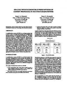
observer take the most work. Figure 4 shows workload associated to each of the observer locations in the MinePump example. Despite the number of reachable SUA locations per observer node, the workload is quite uneven and monopolized by some observer locations. The other examples exhibit a similar pattern. This phenomenon 8 in Section 5.2.1. will be revisited 6 Workload Metric 4 (log) 2 0 0
5
10
15
20
25
Iterations Location 0 Location 1 Location 2
Location 3 Location 4 Location 5
Location 6 Location 7 Location 8
Figure 4. Workload per observer location on MinePump.
The second observation means that the concept of fair distribution needs to be established relative to each iteration. Thus, this justifies the use of the mechanisms for migrating locations (and their future computational work) from one processor to another in each iteration trying to evenly distribute the workload during the whole verification. Unfortunately, efficiently distribute and manipulate zones associated to locations into several processing nodes (as the first observation suggests) seems hard to achieve in backwards verification settings. Indeed, region differentiation used in line 4 of Figure 3(b) (and shown in Figure 2) requires, in principle, performing a DBM operation between each pair of zones in the Cartesian product between Rs and the complement of P redT (recall Section 3). Therefore, it is worth trying to push forward the limit of the presented approach, at least in some common verification scenarios. That is, we would like to improve workload distribution and processor utilization as much as possible without splitting regions. Next section relies on the third observation and a migration strategy based on profiling previous verification sessions on similar models. Together, they improve the performance of the approach reaching reasonable results in the light of the findings presented here.
bos_fmsd-2005.tex; 12/09/2006; 17:36; p.11
30
12
Braberman, Olivero and Schapachnik
5. Redistribution, Workload-Profile Reuse and Observer-Induced Partitioning In order to make the most out of the current approach, we base our analysis on two important observations about how model checking is usually applied: − To reflect improved (faster) components, longer delays or stricter timing requirements it is usual to make small changes to some clock comparisons in the model. − In several verification scenarios, models are actually built from the composition of a SUA with an observer, as already mentioned in Section 1. The importance of these two assumption will become apparent in Section 5.2, after some specific background is presented. 5.1. Dynamic Zeus This section summarizes the results already presented in (Braberman et al., 2004c), about a dynamic version of Zeus. As already reported in (Braberman et al., 2004b) and also shown in Table III, there are important variations of the workload between iterations, even in the subset of the most heavy locations. These variations jeopardize the balance, thus incrementing %waste and consequently the verification times, in the general case. This is why the ability to migrate locations among processors was built into Zeus, in what we call the dynamic version. 5.1.1. Dynamic Location Redistribution Moving locations on-the-fly poses several challenges. This subsection focuses on the technical aspects of the process, postponing the consideration of what, when and where to migrate. Migration decisions are made by the coordinator at the end of each iteration and broadcasted to the capsules along with the clearance to exchange regions. Capsules receive a mapping of locations to their new capsule (at line 4 of Figure 3(a)) and reconfigure their interconnections accordingly. For each location migrated, the originating capsule needs to examine its successors, in order to detect which connectors should be kept active (even adding new ones). This is important because having received updates from every active connector is the trigger to declare the end of the exchange phase (line 6 of Figure 3(a)). To make things harder,
bos_fmsd-2005.tex; 12/09/2006; 17:36; p.12
Dealing with Practical Limitations of Distributed Timed Model Checking
13
some connectors must be flagged temporary active, meaning that they must be kept alive just to migrate locations, but need to be shutdown immediately afterwards. The connectors need to be reconfigured, so they know which locations they are actually serving. Because the topology and boundaries change, there could be connectors to some other capsules no longer needed, and new ones might have to be created. In the last two cases, besides reconfiguring connectors, new embassies might need to be instantiated, or old ones destroyed. More importantly, in many cases region’s data for the affected location needs to be exported by a capsule and imported by another. The corresponding locations are marked, and said regions are exchanged during the region exchange phase (line 5 of Figure 3(a)). Once finished, the migrations list is processed again, so clean up activities can take place, including the removal of former local regions. The result of the process must be that each capsule is reconfigured as if the current partition had never changed since the beginning. Although conceptually simple, implementation details make it a quite involved process. All this reconfiguration time must be added to the transmission delay, implying that migrations are not free, and should be minimized whenever possible. 5.1.2. Coordinator’s Decision Two problems has to be solved to make good migration policies: the workload for the next iteration has to be predicted, and based on that prediction a fair repartitioning has to be found. An important concern is minimizing migration time, because a “perfect” balance makes no sense if it requires a significant delay due to network transmission and, predominantly, the operations described in the previous section. The current version uses the ParMETIS library (Schloegel et al., 2000) which is based on heuristic methods to handle efficiently graph repartitioning problems. ParMETIS tries not only to balance weight while minimizing number of movements, but also to reach minimum cut. Although this would seem like a good idea because it minimizes communication, it is not such a pressing issue in a synchronous environment over a fast local area network. We are still looking for a method that will not aim at minimum cut, so an even better balance could be achieved4 . It should be pointed out that a number of good methods exist for rebalancing in the untimed scenario (see (Heyman et al., 2002, Nicol and Ciardo, 1997) among others). 4
Unluckily ParMETIS does not handle disconnected graphs, so the trick of disregarding the edges can’t be used.
bos_fmsd-2005.tex; 12/09/2006; 17:36; p.13
14
Braberman, Olivero and Schapachnik
Unfortunately they are not directly applicable as they usually don’t have to deal with locations having different (unsplittable) weights. However, prediction for the next iteration is still unaccounted for. 5.1.3. Workload Prediction In (Braberman et al., 2004b) we described an approach based on onthe-fly prediction of the most heavy operation performed by the Fixed Point Engine: region subtraction (line 4 of Figure 3(b)). The reader is referred to the aforementioned article for details as only an outline of the method will be given here. The subtraction operation has two parameters (P redT and Rs ), and its computational complexity depends on its sizes. Although the second is known for the next iteration, the size of P redT is not. In order to obtain reasonable values for it, the following mechanism was developed, based on the intuition that many calculi are usually repeated and some that are not have only slightly different inputs: each time the real operation was performed, the size of its parameters was rounded to its most significant digit, and was stored along with the size of the result. For example, if two regions of size 23456 and 337 were subtracted, obtaining a region of size 128, the tuple h20000, 300, 128i would have been stored. If a new operation has the same rounded parameters size, the old values are overwritten, on the assumption that recent values would predict better future results. When the real value needed to be estimated, its rounded estimated parameters sizes were looked up in the collected information. If no match was found, a default value was used. It should be noted that this is kind of a simplistic approach to best-fit matching, and more sophisticated algorithms could have been used, but it had the advantage of having a small overhead in terms of both space and time, and featured good results. Some case studies showed interesting speedups when using the prediction method. These include RCS6 and MinePump. There were others, however, where accurate predictions could not be made. In the cases where the number of heavy locations was very small and responsible for an important share of the total workload, a failure to predict those locations’ associated work immediately translates into a completely wrong migration set (cft. Section 4). In Section 5.2 a different approach is presented. 5.2. Working Around the Limitations Section 4 presents the problems we believe to be central to the distribution of the backwards model checking algorithm for timed automata, provided that regions are not splitted between processors. The next
bos_fmsd-2005.tex; 12/09/2006; 17:36; p.14
Dealing with Practical Limitations of Distributed Timed Model Checking
15
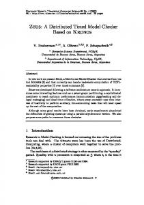
two sections present some observations that complement the technology presented in Section 5.1 to work around them, in the sense that improved results can be achieved in specific settings. 5.2.1. Observer-Based Partitioning An interesting observation can be made over models where the property to verify is expressed via an observer: their topology shares certain characteristics which we detail below. As was said, in several verification scenarios, models are actually built from the composition of a SUA with an observer. Observers can be built in a number of ways: by hand, automatically from formulae (Aceto et al., 1998) or automatically from graphical patterns using tools like VTS (Alfonso et al., 2004). In particular VTS-generated observers are almost a DAG (except for self loops)5 . Roughly speaking, the shape of the observer is like this: an initial location where most of the SUA actions take place, then a few locations meant to synchronize with the negative scenario to be matched, and then the error location. This shape is imposed on the composed system. As Zeus reachability calculus is backwards, the first global locations with some non-empty regions will be the ones corresponding to the last observer locations (typically ERROR labeled). Some iterations later, previous observer locations (i.e., those “closer” to the initial one) will start to accumulate non-empty regions; but because of the many different transitions guards and invariants that have “filtered” those target regions (the aforementioned ERROR regions), they will be more fragmented. That in turn means that the first locations will be heavier to compute in each successive iteration. As was advanced in Section 4, experiments seem to confirm the supposition (recall Figure 4). Taking this phenomenon into account, as well as the previously mentioned non-trivial cost of migrations, evenly distributing the most heavy observer locations among the capsules seems to make sense. Figure 5 shows the speedup of various case studies, for both the traditional round-robin partitioning as well as the new observer-induced distribution. The experiments were run on 9 machines with a 300 MHz R12000 processor, running Irix with 1 GB RAM each. As can be seen in Figure 5, some examples (e.g., RCS6 and RSBR) showed an erratic behavior on the round-robin distribution, but performed very well on the observer-induced. Others, while not close to the desired lineal speedup, were still better than their round-robin counterpart in the overall performance. 5 In this type of observers, reachability of a distinguished location implies the existence of a run of the SUA that matches a given event scenario and hence violates some safety property.
bos_fmsd-2005.tex; 12/09/2006; 17:36; p.15
16
Braberman, Olivero and Schapachnik
5.2.2. Taking Advantage of Common Usage Patterns In order to reflect improved (faster) components, longer delays, stricter timing requirements or some similar variations, it is common to make small changes to some clock comparisons in the model, as was advanced at the beginning of Section 5. Although these modifications can drastically change the output of the verification, in usual cases found in practice, they have little impact. In those verification scenarios, information from previous runs can be used to create an initial fair partitioning, and to migrate locations based on trustable workload data. The procedure is as follows: migrations are produced offline based on the workload data of the unmodified system –called original from now on– and using ParMETIS to calculate them. The tool is instructed to avoid migrations if the workload is below a configurable threshold. That typically means that the first iterations are migration free. To improve things a little bit, the initial partition is created as the previously mentioned observer-induced one, modified by the first non-empty migration. An interesting point to note is that this fast offline preparation can also compute a theoretical %waste metric and compare it to the %waste metric of the original run, on an iteration basis. Two purposes are served by this comparison: first, if the theoretical waste is more that the actual run, the migrations can be discarded for this iteration. More importantly, if during the run an important divergence between the theoretical and the real per-capsule metric is detected, the tool can conclude that the change in the model was indeed important, making the model (very) different from the original, and thus disregards the remaining migrations. In order to exercise these ideas all the models were modified as follows: − RCS6 : the controller was made two time units slower. − Conveyor4AB and Conveyor6A: the task that starts when an object is detected and ends when it is lifted from the conveyor belt was given a stricter deadline by ten time units. − RS-BR and RS-C : the WCCTs of the readers were relaxed and unequaled. − MinePump: the WCCT of the watchdog was strengthened. Analyzing preliminary performance of the modified models with observer-induced partitions vs. observer-induced partitions plus migrations based on the workload data of the original example, we noticed
bos_fmsd-2005.tex; 12/09/2006; 17:36; p.16
Dealing with Practical Limitations of Distributed Timed Model Checking
17
that na¨ıve migrations do not seem to add value, even decreasing performance on some cases. For instance, Conveyor4AB requires 3216 seconds on a monoprocessor and 1627 in two processors without migrations. If na¨ıve migrations are used, the two-processor verification requires 3859 seconds, i.e., more than the original. We found the explanation for that phenomenon again in Table II. Case studies where the number of heavy locations is small will suffer an important migration overhead. This is because ParMETIS needs to move many of locations to compensate for one of these, and as was said earlier, each migrated location requires non-trivial amounts of work, independently of its region’s size, thus increasing the total verification time. To counter this downside, we refined the migration strategy: let ParMETIS do its job, but then only migrate (as instructed by ParMETIS) the most heavy locations. This will of course produce a more unbalanced workload pattern, but the expected gain is to compensate that with a smaller migration overhead. Another heuristic idea is used: as Zeus checks for the presence of the initial (timed) state in the reached set in each iteration (that is, not only when the fixed point is reached), if the expected outcome is “true”, then it doesn’t make sense to move locations on the (expected) last iteration, because that would only delay the moment where the initial location is processed. Table IV shows the times for the case studies with migrations, versus only an observer-induced partition. In some cases –notably RS-BR and RS-C – a decrease in time is not followed by a decrease in %waste. This is caused by the difference in I/O times involved, consequence of different communication requirements due to changed partition boundaries (cft. %waste formula in Section 4). Figure 5 shows the speedup gained: the migration method improves performance on most of the cases. Based on the information summarized in Table II, we postulate that these speedups are almost as good as they can get without splitting the workload per location. This has to do with the fact that it is not reasonable to expect good performance on n processors if there are only m locations monopolizing most of the workload (with m < n). More precisely, Table II justifies why the quasi-linear speedup cannot go beyond a certain threshold. For example, Conveyor4AB has four locations taking approximately 20% of the work each one on its heaviest iteration. Considering that in many cases (such as Conveyor4AB ) the heaviest iteration conditions the total time, this means that there is no current way to achieve a speedup substantially greater than five, in this example. However, if in the future Zeus were run on a mixed network of workstations, some of them single processor, some of them multi-, it would make sense to use migrations to take heavy –nowadays unsplittable–
bos_fmsd-2005.tex; 12/09/2006; 17:36; p.17
18
Braberman, Olivero and Schapachnik
Table IV. Total time in kilo seconds and (%waste) obtained for different distributions. Example
Distrib.
MinePump
RR
Original
OI
MinePump
RR
Modified
OI
2
3
4
7
8
9
13.17
10.63 (41) 11.29 (44)
10.43 (60) 7.83 (47)
10.54 (70) 7.16 (57)
10.56 (77) 9.78 (74)
10.59 (80) 6.87 (70)
10.46 (83) 6.53 (73)
9.45 (84) 6.66 (77)
9.50 (85) 6.73 (80)
13.25
11.54 (45) 11.44 (44) 6.98 (30)
7.88 (47) 7.87 (46) 6.85 (42)
7.45 (59) 7.23 (57) 6.61 (55)
10.12 (80) 9.92 (74) 6.82 (65)
7.23 (75) 6.94 (70) 7.08 (70)
7.12 (75) 6.60 (73) 6.31 (74)
7.08 (78) 6.72 (77) 6.56 (78)
6.91 (82) 6.82 (80) 6.42 (79)
6.91
3.64 (07) 3.67 (08)
2.43 (08) 2.51 (11)
2.41 (31) 1.87 (10)
3.70 (64) 1.66 (19)
3.13 (65) 1.30 (13)
2.44 (61) 1.44 (33)
1.75 (53) 1.12 (25)
1.29 (43) 1.13 (34)
5.41
2.85 (07) 2.85 (08) 2.75 (04)
1.89 (08) 1.95 (11) 1.81 (04)
1.90 (31) 1.45 (10) 1.37 (05)
2.86 (64) 1.27 (18) 1.21 (12)
2.45 (65) 1.00 (13) 1.02 (15)
1.90 (61) 1.09 (31) 0.90 (13)
1.38 (53) 0.86 (24) 0.76 (11)
1.01 (43) 0.86 (32) 0.75 (21)
3.23
2.31 (31) 1.63 (02)
1.55 (31) 1.56 (31)
1.54 (48) 1.49 (45)
2.32 (73) 1.45 (54)
2.28 (77) 1.42 (61)
1.55 (71) 0.82 (43)
1.51 (74) 0.78 (48)
0.81 (56) 0.84 (56)
3.21
2.35 (31) 1.63 (02) 1.52 (02)
1.56 (31) 1.56 (31) 1.28 (28)
1.55 (48) 1.48 (44) 0.92 (10)
2.33 (73) 1.44 (55) 0.76 (14)
2.30 (77) 1.42 (61) 0.72 (24)
1.56 (70) 0.82 (43) 0.73 (36)
1.53 (74) 0.77 (47) 0.71 (43)
0.82 (56) 0.84 (57) 0.71 (49)
5.30
3.43 (26) 3.61 (29)
3.37 (49) 3.38 (50)
3.34 (62) 3.50 (64)
3.37 (70) 3.34 (70)
3.38 (75) 3.26 (74)
3.28 (78) 3.32 (79)
3.28 (81) 3.26 (81)
3.26 (83) 3.11 (82)
5.36
3.45 (26) 3.62 (29) 2.36 (28)
3.34 (49) 3.38 (50) 3.24 (49)
3.36 (62) 3.52 (64) 3.16 (61)
3.44 (70) 3.34 (70) 3.18 (68)
3.42 (75) 3.26 (74) 3.27 (74)
3.32 (79) 3.32 (79) 3.05 (78)
3.31 (81) 3.26 (81) 2.96 (79)
3.30 (83) 3.11 (82) 3.05 (82)
9.71
4.16 (19) 4.68 (10)
3.10 (14) 2.91 (17)
2.55 (34) 2.49 (27)
2.65 (68) 1.89 (40)
2.58 (66) 1.55 (32)
2.04 (63) 1.43 (36)
1.95 (60) 1.24 (37)
1.58 (53) 1.20 (44)
9.59
4.13 (20) 4.63 (10) 4.61 (10)
3.09 (16) 2.87 (17) 2.95 (11)
2.54 (35) 2.46 (27) 3.49 (29)
2.63 (68) 1.85 (40) 2.42 (27)
2.55 (66) 1.52 (32) 2.10 (20)
2.02 (63) 1.40 (37) 1.73 (29)
1.92 (61) 1.24 (38) 1.10 (39)
1.55 (54) 1.20 (44) 1.02 (36)
4.76
1.62 (40) 3.91 (39)
1.38 (53) 1.44 (54)
1.32 (64) 1.39 (64)
1.33 (75) 1.32 (71)
1.27 (75) 1.17 (75)
1.19 (78) 1.16 (78)
1.13 (80) 1.10 (80)
1.06 (82) 1.07 (82)
4.77
1.64 (40) 3.93 (40) 3.91 (39)
1.40 (53) 1.46 (54) 1.68 (51)
1.31 (63) 1.38 (65) 1.49 (63)
1.35 (75) 1.33 (70) 1.15 (71)
1.30 (75) 1.19 (75) 1.11 (75)
1.25 (78) 1.17 (78) 1.06 (77)
1.20 (80) 1.09 (80) 1.03 (80)
1.07 (82) 1.08 (82) 1.02 (82)
OI+migr
RCS6
RR
Original
OI
RCS6
RR
Modified
OI OI+migr
Conveyor4AB
RR
Original
OI
Conveyor4AB
RR
Modified
OI OI+migr
Conveyor6A
RR
Original
OI
Conveyor6A
RR
Modified
OI OI+migr
RS-BR
RR
Original
OI
RS-BR
RR
Modified
OI OI+migr
RS-C
RR
Original
OI
RS-C
RR
Modified
OI OI+migr
Processors 5 6
1
bos_fmsd-2005.tex; 12/09/2006; 17:36; p.18
9 9 8 8 7 7 6 6 5 Speedup5 Speedup 4 4 3 Timed Model Checking 3 Dealing with Practical Limitations of Distributed 19 2 2 1 1 90 90 17 28 39 410 5 6 7 1 2 3 4 5 8 06 8 0 7 7 Processors Processors 6 6 RR partitioning RR5partitioning Speedup Speedup5 OI partitioning OI partitioning 4 migrations 4 OI partitioning+restr. migrations OI partitioning+restr. 3 3 (b) RCS6 . (a) MinePump. 2 2 1 1 90 90 17 28 39 410 5 6 7 1 2 3 4 5 8 06 8 0 7 7 Processors Processors 6 6 RR partitioning RR5partitioning Speedup Speedup5 OI partitioning OI partitioning 4 migrations 4 OI partitioning+restr. migrations OI partitioning+restr. 3 3 (d) Conveyor6A. (c) Conveyor4AB . 2 2 1 1 0 0 06 17 28 39 410 5 6 7 0 1 2 3 4 5 Processors
Processors RR partitioning OI partitioning OI partitioning+restr. migrations (e) RS-BR.
RR partitioning OI partitioning OI partitioning+restr. migrations
(f) RS-C .
Figure 5. Speedups for observer-induced (OI) partitions with and without migrations for the constraint-modified case studies.
locations to a multiprocessor where various threads can work on it at the same time. It should be pointed out that the combined method is far superior to the na¨ıve round-robin distribution reported in a previous article (Braberman et al., 2004b). There is another interesting advantage to be gained in these kind of scenarios where a verification is run over a model slightly different from a previous one: from the data of Table II an estimation can be made on the number of processors to use. That is, intuition might suggest to use as many processors as available, but if the model is really similar
bos_fmsd-2005.tex; 12/09/2006; 17:36; p.19
8
9
8
9
8
9
20
Braberman, Olivero and Schapachnik
to the previous one, it might make sense to use only a subset of them, freeing the remaining ones for some other use. The aforementioned idea will become specially important once the next generation of multi-core processors becomes popular. It is common for engineers to make incremental changes to the model and leave the model checker in background while they continue working on other tasks. With this information at hand, the model checker can be prevented from consuming all the processing power of the workstation without degrading its own performance. 6. Conclusions and Future Work Zeus is a distributed model checker for timed automata models based on the classical technique –known as backwards calculus– of fixed point computation of the set of reachable states, using DBMs as main representation structure. Parallel computation is achieved by a location-based distribution (i.e., during a fixed point iteration, all DBMs associated to a discrete location are treated by the same processing node). Thus, the component and connector deployment architecture is automatically reconfigured according to the number of processors and the way that a discrete location graph is distributed among those processors. Though asynchronous computation of fixed point is theoretically sound, DBM-based data structures may be inefficient when the exploration order differs from that of the monoprocessor version. This justifies that, currently, iterations in each processing node are synchronized thus mimicking the sequential algorithm. Unfortunately, this also leads to wasted times because of processing nodes waiting for the signal that authorizes the next iteration, which is sent just after all processing nodes have finished the current fixed point iteration computation. Thus, load balance becomes the key factor to achieve speedups in practice. However, as Section 4 shows, some locations monopolize the total workload, meaning that close-to-linear speedups are not feasible without splitting locations among processors, which in turn seems impractical for the backwards calculus in a distributed environment (i.e., no shared-memory). Nevertheless, Zeus seems to get the most out of the availability of processors given this essential limitation of the location-based approach. Preliminary observations lead us to the supposition that this parameter seems to be related to the number of feasible simple paths in the analyzed design. For instance, the more parallel activity (represented by interleaving actions) the better suited for distribution using Zeus techniques and the more scalable its verification (that is linear
bos_fmsd-2005.tex; 12/09/2006; 17:36; p.20
Dealing with Practical Limitations of Distributed Timed Model Checking
21
speedups are achieved for larger clusters). This seems an interesting property since it suggests that the location-based approach may be useful for highly asynchronous designs. We plan to explore this idea deeper in the future. In this article we present new techniques to improve load balance in some verification settings in order to achieve better speedups. Firstly, we leverage on the fact that observer-based analysis of a design is a common practice in verification, and accordingly distribute locations evenly wrt. the accompanying observer location. Secondly, when the verification engineer analyzes a new version of the system where only deadlines and delays are modified, we explore how to reuse effort metrics collected for the original model. This technique achieves reuse by migrating locations among processing nodes trying to balance the likely effort in each iteration, without incurring in a high redistribution overhead. On one hand, experiments show that these heuristics have some positive impact on load balance and some interesting speedups are achieved for small sized clusters. On the other hand, as previously mentioned, the number of locations associated to most of the computation effort during each iteration (m) still sets a practical limit on the expectation to get linear speedups for a given number of processors (i.e., n processors would be of no help if m is less than n), without splitting regions. When the reuse technique is applied, that number may be useful to suggest to the verification engineer the number of processors that should be involved for an efficient model checking of a system variant. We consider this finding, and specially the possibility of estimating it a priori on the reuse scenario, a key one. Zeus is currently distributed, but with the next generation of multicore processors becoming popular and our founding that only a limited number of locations are responsible for most of the workload (recall Table II), it might make sense to develop a parallel-distributed hybrid version. It would work in a distributed cluster, but multi-processor nodes would be multi-threaded, parallelizing the work also on the location level. In that settings, migrations might play a key role, because heavy locations could be moved to dense-processor nodes in each iteration. Future work agenda also includes, on one hand, revisiting the asynchronous fixed point computation strategy while changing the underlying data structure to avoid the before-mentioned fragmentation phenomena. On the other hand, we plan to work at a finer level of distribution granularity in the current synchronous DBM-based version by splitting work of heavy-weighted discrete locations if they are few compared to the number of available processors, as well as trying to
bos_fmsd-2005.tex; 12/09/2006; 17:36; p.21
22
Braberman, Olivero and Schapachnik
find a way to predict a priori the maximum possible speedup, in order to assign only the needed resources to the model checker. References Aceto, L., A. Burgue˜ no, and K. G. Larsen: 1998, ‘Model Checking via Reachability Testing for Timed Automata’. In: Tools and Algorithms for Construction and Analysis of Systems (TACAS ’98). pp. 263–280. Alfonso, A., V. Braberman, N. Kicillof, and A. Olivero: 2004, ‘Visual Timed Event Scenarios’. In: Proc. of the 26th ACM/IEEE International Conference on Software Engineering. Altisen, K. and S. Tripakis: 2002, ‘Tools for Controller Synthesis of Timed Systems’. In: RT-TOOLs. Alur, R., C. Courcoubetis, D. Dill, N. Halbwachs, and H. Wong-Toi: 1992, ‘An Implementation of three algorithms for timing verification based on automata emptiness’. In: Proceedings of the 13th IEEE Real-time Systems Symposium. Phoenix, Arizona, pp. 157–166. Alur, R., C. Courcoubetis, and D. L. Dill: 1993, ‘Model-Checking in Dense Realtime’. Information and Computation 104(1), 2–34. Alur, R. and D. L. Dill: 1994, ‘A theory of timed automata’. Theoretical Computer Science 126(2), 183–235. Barnat, J., L. Brim, and J. Str´ıbˇrn´ a: 2001, ‘Distributed LTL Model-Checking in SPIN’. In: M. B. Dwyer (ed.): Proc. of the 8th International SPIN Workshop. Toronto, Canada, pp. 200–216. Behrmann, G.: 2005, ‘Distributed reachability analysis in timed automata’. International Journal of Software Tools for Technology Transfer 7(1), 19–30. Behrmann, G., T. Hune, and F. W. Vaandrager: 2000, ‘Distributing Timed Model Checking - How the Search Order Matters’. In: Computer Aided Verification, Vol. 1855 of LNCS. pp. 216–231. Ben-David, S., T. Heyman, O. Grumberg, and A. Schuster: 2000, ‘Scalable Distributed On-the-Fly Symbolic Model Checking’. In: Formal Methods in Computer-Aided Design. pp. 390–404. Bengtsson, J., K. G. Larsen, F. Larsson, P. Pettersson, and W. Yi: 1995, ‘UPPAAL - a Tool Suite for Automatic Verification of Real-Time Systems’. In: Hybrid Systems. pp. 232–243. Bollig, B., M. Leucker, and M. Weber: 2001, ‘Parallel Model Checking for the Alternation Free µ-Calculus’. In: 7th International Conference on Tools and Algorithms for the Construction and Analysis of Systems (TACAS ’01), Vol. 2031 of LNCS. pp. 543–558. Bozga, M., C. Daws, O. Maler, A. Olivero, S. Tripakis, and S. Yovine: 1998, ‘Kronos: A Model-Checking Tool for Real-Time Systems’. In: Proc. of the 10th Intl. Conf. CAV ’98, Vol. 1427 of LNCS. pp. 546–550. Braberman, V.: 2000, ‘Modeling and Checking Real-Time Systems Designs’. Ph d. thesis, Departamento de Computaci´ on, Facultad de Ciencias Exactas y Naturales, Universidad de Buenos Aires. Braberman, V., D. Garbervetsky, and A. Olivero: 2004a, ‘ObsSlice: A timed automata slicer based on Observers’. In: Proc. of the 16th Intl. Conf. CAV ’04. Braberman, V., A. Olivero, and F. Schapachnik: 2002, ‘Zeus: A Distributed Timed Model Checker Based on Kronos’. In: 1st Workshop on Parallel and Distributed
bos_fmsd-2005.tex; 12/09/2006; 17:36; p.22
Dealing with Practical Limitations of Distributed Timed Model Checking
23
Model Checking, affiliated to CONCUR 2002 (13th International Conference on Concurrency Theory), Vol. 68 of ENTCS. Brno, Czech Republic. Braberman, V., A. Olivero, and F. Schapachnik: 2004b, ‘Issues in Distributed ModelChecking of Timed Automata: building Zeus’. International Journal of Software Tools for Technology Transfer p. Online First. Braberman, V., A. Olivero, and F. Schapachnik: 2004c, ‘On-the-fly Workload Prediction and Redistribution in the Distributed Timed Model Checker Zeus’. In: 3rd International Workshop on Parallel and Distributed Methods in verifiCation, affiliated to CONCUR 2004 (15th International Conference on Concurrency Theory). London, UK. Cousot, P.: 1978, ‘Methodes Iteratives de Construction et D’Aproximation de Points Fixes D’Operateurs Monotones sur un Treillis, Analyse Semantique des Programmes’. Ph d. thesis, Universit´e Scientifique et M´edicale de Grenoble, Institut National Polytechnique de Grenoble. Daws, C. and S. Yovine: 1996, ‘Reducing the Number of clock Variables of Timed Automata’. Proceedings IEEE Real-Time Systems Symposium (RTSS ’96) pp. 73–81. Dill, D. L.: 1990, ‘Timing Assumptions and Verification of Finite-State Concurrent Systems.’. In: International Workshop of Automatic Verification Methods for Finite State Systems, Vol. 407 of LNCS. Grenoble, France, pp. 197–212. Garavel, H., R. Mateescu, and I. M. Smarandache: 2001, ‘Parallel State Space Construction for Model-Checking’. In: M. B. Dwyer (ed.): Proc. of the 8th International SPIN Workshop. Toronto, Canada, pp. 217–234. Grumberg, O., T. Heyman, and A. Schuster: 2001, ‘Distributed Symbolic Model Checking for µ-Calculus’. In: Computer Aided Verification. pp. 350–362. Heljanko, K., V. Khomenko, and M. Koutny: 2002, ‘Parallelisation of the Petri Net Unfolding Algorithm’. In: Tools and Algorithms for Construction and Analysis of Systems (TACAS ’02). pp. 371–385. Henzinger, T. A., X. Nicollin, J. Sifakis, and S. Yovine: 1994, ‘Symbolic Model Checking for Real-Time Systems’. Information and Computation 111(2), 193– 244. Heyman, T., D. Geist, O. Grumberg, and A. Schuster: 2002, ‘Achieving Scalability in Parallel Reachability Analysis of Very Large Circuits’. Formal Methods in System Design 21(2), 317–338. Krcal, P.: 2003, ‘Distributed Explicit Bounded LTL Model Checking’. In: L. Brim and O. Grumberg (eds.): Electronic Notes in Theoretical Computer Science, Vol. 89 of ENTCS. Lerda, F. and R. Sisto: 1999, ‘Distributed-memory Model Checking with SPIN’. In: Proc. of the 5th International SPIN Workshop, Vol. 1680 of LNCS. Nicol, D. M. and G. Ciardo: 1997, ‘Automated Parallelization of Discrete State-Space Generation’. Journal of Parallel and Distributed Computing 47(2), 153–167. Pnueli, A.: 2005, ‘Extracting Controllers for Timed Automata’. Technical report, Department of Computer Science, Weizmann Institute of Science. Ranjan, R., J. Sanghavi, R. Brayton, and A. Sangiovanni-Vincentelli: 1996, ‘Binary Decision Diagrams on Network of Workstations’. In: International Conference on Computer Design. pp. 358–364. Schapachnik, F.: 2002, ‘Distributed and Parallel Verification of Real-Time Systems’. Degree thesis, Departamento de Computaci´ on, Facultad de Ciencias Exactas y Naturales, Universidad de Buenos Aires. Schloegel, K., G. Karypis, and V. Kumar: 2000, ‘A Unified Algorithm for Loadbalancing Adaptive Scientific Simulations’. Technical report, University of
bos_fmsd-2005.tex; 12/09/2006; 17:36; p.23
24
Braberman, Olivero and Schapachnik
Minnesota, Department of Computer Science / US Army HPC Research Center. Minneapolis, USA. Stern, U. and D. L. Dill: 1997, ‘Parallelizing the Murϕ Verifier’. In: Computer Aided Verification, Vol. 1254 of LNCS. pp. 256–278.
bos_fmsd-2005.tex; 12/09/2006; 17:36; p.24