detection, recognition, etc. ... analysis, vehicle number plate detection and identification, etc. ..... can track these robots based on OpenCV Camshift tracker. The.
Decision-Theoretic Approach to Maximizing Observation of Multiple Targets in Multi-Camera Surveillance Prabhu Natarajan, Trong Nghia Hoang, Kian Hsiang Low, and Mohan Kankanhalli Department of Computer Science, National University of Singapore Computing 1, 13 Computing Drive, Singapore 117417, Republic of Singapore
{prabhu, nghiaht, lowkh, mohan}@comp.nus.edu.sg ABSTRACT This paper presents a novel decision-theoretic approach to control and coordinate multiple active cameras for observing a number of moving targets in a surveillance system. This approach offers the advantages of being able to (a) account for the stochasticity of targets’ motion via probabilistic modeling, and (b) address the tradeoff between maximizing the expected number of observed targets and the resolution of the observed targets through stochastic optimization. One of the key issues faced by existing approaches in multi-camera surveillance is that of scalability with increasing number of targets. We show how its scalability can be improved by exploiting the problem structure: as proven analytically, our decision-theoretic approach incurs time that is linear in the number of targets to be observed during surveillance. As demonstrated empirically through simulations, our proposed approach can achieve high-quality surveillance of up to 50 targets in real time and its surveillance performance degrades gracefully with increasing number of targets. We also demonstrate our proposed approach with real AXIS 214 PTZ cameras in maximizing the number of Lego robots observed at high resolution over a surveyed rectangular area. The results are promising and clearly show the feasibility of our decision-theoretic approach in controlling and coordinating the active cameras in real surveillance system.
Categories and Subject Descriptors I.4.8 [Scene Analysis]: Tracking; I.2.9 [Robotics]: Commercial robots and applications, Sensors
General Terms Algorithms, Performance, Experimentation, Security
Keywords Active camera networks, Smart camera networks, Multi-camera coordination and control, Surveillance and security
1.
INTRODUCTION
The use of active cameras in surveillance is becoming increasingly popular due to the recent advances in smart camera technologies [4]. These active cameras are endowed with pan, tilt, and zoom Appears in: Proceedings of the 11th International Conference on Autonomous Agents and Multiagent Systems – Innovative Applications Track (AAMAS 2012), Conitzer, Winikoff, Padgham, and van der Hoek (eds.), 4-8 June 2012, Valencia, Spain. c 2012, International Foundation for Autonomous Agents and Copyright Multiagent Systems (www.ifaamas.org). All rights reserved.
capabilities, which can be exploited to provide high-quality surveillance. In order to achieve effective, real-time surveillance, an efficient collaborative mechanism is needed to control and coordinate these cameras’ actions, which is the focus of our work in this paper. Monitoring a set of targets moving in an environment is a challenging and difficult task because (a) the motion of these targets is often stochastic in nature, (b) it needs to address the non-trivial trade-off between maximizing the expected number of observed targets and the resolution of the observed targets, and (c) a camera coordination framework should be scalable with an increasing number of targets. To elaborate, (a) the uncertainty in the targets’ motion makes it hard for the active cameras to know where to observe in order to keep these targets within their fields of view (fov) and they may consequently lose track of the observed targets, (b) increasing the resolution of observing some targets through panning, tilting, or zooming may result in the loss of other targets being tracked, and (c) when the number of targets increases, a camera coordination framework, if poorly designed, tends to incur exponentially increasing computational time, which degrades the performance of the entire system. These issues arise in many realworld surveillance applications such as target surveillance, observing a group of players in sports, industrial monitoring of protected sites, etc. Hence, we believe that, by addressing these practical issues, a more effective surveillance system can be realized and subsequently deployed in the real world. Note that our proposed surveillance task differs from the typical sensor coverage problem, the latter of which instead focuses on maximizing the spatial coverage of the cameras that are independent of targets’ motion. In our work, we try to maximize the coverage of the observed targets in the environment. This paper presents a novel principled decision-theoretic approach to control and coordinate the active cameras for the surveillance of multiple moving targets (Section 2). This approach is based on the Markov Decision Process (MDP) framework, which allows the surveillance task to be framed formally as a stochastic optimization problem (Sections 3 and 4). In particular, our MDP-based approach resolves the above-mentioned issues: (a) the motion of the targets can be modeled probabilistically (Section 4.2), and (b) to address the trade-off, the active cameras’ actions are coordinated to maximize the expected number of observed targets while guaranteeing a pre-defined resolution of these observed targets (Section 4.4), and (c) the scalability can be improved by exploiting the problem structure: as proven analytically (Section 4.5), our MDP-based approach incurs time that is linear in the number of targets to be observed during surveillance. One key problem faced by existing multi-camera multi-target surveillance approaches is that of scalability with increasing number of targets (Section 2). As demonstrated empirically through simulations (Section 5), our MDP-based approach
Table 1: Comparison of related work based on (a) camera:target ratio, (b) primary criterion, and (c) uncertainty in targets’ motion. Surveillance/tracking strategy Banerjee et al. [3] Costello et al. [5] Krahnstoever et al. [9] Qureshi et al. [13] Soto et al. [15] Sommerlade et al. [14] Huang et al. [8] Alfy et al. [6] Proposed MDP-based approach
n�m
n�m
n=m ×
× × × × × × ×
RELATED WORK
Our proposed work is compared and contrasted with existing approaches for active camera surveillance based on the following classification: (a) ratio of number n of cameras to number m of targets, (b) primary criterion - the main objective/goal of the surveillance system, and (c) uncertainty in targets’ motion - whether the targets’ motion uncertainty is considered in camera coordination and optimal decision making. This comparison is shown in Table 1. The camera:target ratio is further classified based on n � m, n � m, and n = m. The camera:target ratio plays an important role in the choice of primary criterion that is used in the existing works, as explained below. The primary criterion is classified into: (i) maximizing the number of observed targets with certain guaranteed resolution and (ii) minimizing the uncertainty of individual targets’ locations. The targets’ motion is stochastic in nature and hence needs to be predicted and subsequently exploited for coordinating the cameras in a typical surveillance system. The existing works are also classified based on whether they have accounted for the uncertainty in targets’ motion in their optimization framework. Table 1 shows that when the camera:target ratio is either n = m [3] or n � m [5, 6, 8, 9, 13, 14, 15], the primary criterion is to minimize the uncertainty of individual targets’ locations. By observing individual targets with more cameras, the uncertainty of targets’ locations is decreased. In contrast, when the camera:target ratio is n � m, the primary criterion is to maximize the number of observed targets in the environment. In either criterion, the targets’ motion is inherently non-deterministic. But, none of the previous works have accounted for the motion uncertainty in their optimization framework. The works of [2, 12] aim to maximize the coverage of static targets in omni-directional active sensors. Since the targets are static, there is no notion of stochasticity of targets’ motion. All the above-mentioned works use heuristic approaches to select the best actions for the active cameras. Such approaches are therefore tailored specifically to their own objectives and cannot be modified to achieve other objectives. In contrast, our approach is a general framework in which different surveillance goals can be modeled as formal objective functions. To summarize, our proposed work is different from the existing works in the following ways: (a) we use a formal, principled Markov Decision Process (MDP) framework to select the optimal actions for active cameras to maximize the expected number of ob-
Minimizing uncertainty of targets’ locations × × × × × × × ×
×
×
can achieve high-quality surveillance of up to 50 targets in real time and its surveillance performance degrades gracefully with an increasing number of targets. The real-world experiments (Section 5.3) show the practicality of our decision-theoretic approach to control and coordinate cameras in surveillance systems.
2.
Maximizing no. of observed targets
Uncertainty in targets’ motion
×
served targets; (b) we account for the uncertainty in targets’ motion by integrating a probabilistic motion model into our optimization framework; and (c) many previous works ([9, 13, 14, 16], etc.) face a serious scalability issue in terms of the number of targets to be observed. We shall show in later sections how the state space of the targets can be managed efficiently by exploiting the structure and properties that are inherent in the surveillance problem.
3.
SYSTEM ARCHITECTURE
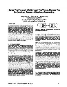
The proposed surveillance framework consists of a supervised surveillance environment and an MDP controller. The environment consists of targets, static cameras, and active cameras. The targets are the moving objects (e.g., people, vehicles, robots, etc.) in the surveillance environment whose motions are stochastic in nature. The static cameras are wide-view cameras that can only provide low-quality information of the surveillance environment. These cameras are assumed to be calibrated and can get the 3D location, direction, and velocity information of the targets. The active cameras are PTZ (pan/tilt/zoom) cameras that can get high-resolution images of the targets in the environment. The MDP controller models the interaction between the active cameras and the environment, and provides a platform to choose optimal actions for these cameras in order to achieve high-quality surveillance tasks. Fig. 1 shows the top view of a representative surveillance environment where the full fov’s of the active cameras are shown in dotted lines and the current active fov’s are shaded. For simplicity, the static cameras are not shown. The active cameras are placed such that they can observe the complete environment by pan/tilt/zoom operations but cannot observe all locations of the environment simultaneously. This makes the problem more practical and challenging, thus emphasizing the need to control these active cameras. The static cameras determine the location, direction, and velocity of targets and pass these information to the MDP controller. Based on these information, the MDP controller computes the optimal actions of active cameras such that the expected utility of the surveillance system is maximized. The utility of the surveillance system corresponds to the high-level application goal that can be defined formally using a real-valued objective function, as described in Section 4.4. Formally, the MDP controller is defined as a tuple (S, A, R, Tf ) consisting of a set S of discrete states of active cameras and targets, a set A of joint actions of active cameras, a reward function R : S → R representing the high-level surveillance goal, and a transition function Tf : S × A × S → [0, 1] denoting the probability P (S 0 |S, A) of switching from the current state S ∈ S to the next state S 0 ∈ S using the joint action A ∈ A. In the MDP framework, the policy function π : S → A maps from each state to
0o
MDP Controller
45o
target location
+45o
camera 7
camera 6
Door
Actions for each active camera
camera 5
camera 1
camera 4
Door
camera 8
90o
Wall
camera 2
camera 3
Figure 1: System architecture.
a joint action of the cameras. Solving the MDP involves choosing the policy that maximizes the expected reward for any given state. The optimal policy, denoted by π ∗ , maximizing the expected utility of the system in the next time step is given by X π ∗ (S) = arg max R(S 0 ) P (S 0 |S, A) . A∈A
S 0 ∈S
The main challenge in the MDP is managing the state space S and action space A. This is because the state space grows exponentially in the number of active cameras and targets. Hence, the policy computation time for our surveillance problem is exponential. In practice, the structure of the problem and environment can usually be exploited to reduce the number of states and the time required to compute the optimal policy. We will show in Section 4.5 how the state space can be managed for our surveillance problem, thus allowing the MDP to be solved more efficiently. The following assumptions are made in our surveillance task: • The targets are oblivious to the cameras, in particular, non-evasive (i.e., they do not try to escape from the cameras’ fields of view) and their motion cannot be controlled nor influenced; • The static cameras are calibrated accurately such that the 3D positioning errors of the targets are minimal. This can be achieved by placing the cameras at high altitude; • The total number of targets in the environment can be obtained from static cameras and/or motion sensors at the entry and exit.
4.
(0,0) (0,1) (0,2) (0,3) (0,4) (0,5)
PROBLEM FORMULATION
Given a set of cameras and targets in a surveillance system, the MDP controller determines the optimal actions for these cameras such that the expected utility of the surveillance system is maximized. In this section, we describe how an MDP framework can be applied to a generic active camera surveillance in order to maximize the expected utility of the surveillance system. We enumerate each component of the MDP framework and show how these components can be formulated for a typical surveillance system. In this work, the objective/reward function of the MDP modeling the high-level surveillance goal measures the total number of targets observed by active cameras with a guaranteed resolution. Maximizing the number of observed targets with a guaranteed resolution is a mandatory task in surveillance because we need to obtain the high-resolution images of targets for bio-metric tasks like target
ci = +45o
+90o
(1,0) (1,1) (1,2) (1,3) (1,4) (1,5)
Wall
(2,0) (2,1) (2,2) (2,3) (2,4) (2,5) (3,0) (3,1) (3,2) (3,3) (3,4) (3,5)
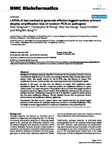
(a) (b) Figure 2: (a) Camera states and (b) target locations. detection, recognition, etc. In this work, we present a decisiontheoretic approach for maximizing the expected number of targets observed by the active cameras.
4.1
States and Actions
A state of the MDP comprises the states of active cameras and targets in the surveillance environment. The passive static cameras are first calibrated based on common ground plane coordinates and then used to obtain the targets’ approximate 3D location, velocity, and the direction information. Let n be the number of active cameras and m be the number of targets in the environment such that n � m. In this manner, the surveillance problem becomes more challenging and interesting since there are more targets to be monitored by fewer active cameras. Let the set of possible states of each active camera in the environment be denoted by C such that each state ci ∈ C corresponds to a discretized pan/tilt/zoom position of camera i. For example, in Fig. 2a, the set of possible states of camera i based on discretized pan angles is given by C = {+90 ◦ , +45 ◦ , 0 ◦ , −45 ◦ , −90 ◦ } and the current state ci is +45 ◦ . Let the state space of a target be represented by a set of tuples of location, direction and velocity, and denoted by T = Tl × Td × Tv where Tl denotes a set of all possible locations of the target in the environment, Td denotes a set of all possible discretized directions between all pairs of locations in Tl , and Tv denotes a set of discretized velocities of the target. The surveillance environment is discretized into grid cells such that the centers of the grid cells represent the possible locations of a target, as shown in Fig. 2b. The approximate 3D location of the target observed by static cameras will be mapped to the center of the nearest grid cell. The direction and velocity of the target are determined based on its current and previous locations. The static cameras detect the targets in their fov’s and report their locations, directions, and velocities to the MDP controller. By calibrating the active cameras, the possible target locations in the environment that lie within the fov of each active camera in its various states can be pre-computed. For each state ci ∈ C of active camera i, the subset of locations lying within its corresponding fov is denoted by f ov(ci ) ⊂ Tl . For example, Fig. 3 illustrates the fov (i.e., shaded polygon) of active camera 1 in its current state c1 ; the subset of locations that are observed by camera 1 is given by f ov(c1 ) = {(0, 1), (0, 2), . . . , (2, 3), (2, 4)}. To observe targets with a guaranteed resolution, the zoom parameter of an active camera can be adjusted to focus its fov so that imageries of the targets detected within its fov satisfy a pre-defined resolution. This requires limiting the depth of its fov, as depicted by the horizontal line in Fig. 3. As a result, if a target is located within f ov(ci ) of any camera i, then it is observed with a guaranteed resolution. For example, the minimum resolution of the human face should be 24 × 24 pixels, which is the base resolution for face detection [18]. The resolution of the targets should be higher than
camera 1 fov(c1) (0,0) (0,1) (0,2) (0,3) (0,4) (0,5) (1,0) (1,1) (1,2) (1,3) (1,4) (1,5)
(2,0) (2,1) (2,2) (2,3) (2,4) (2,5) (3,0) (3,1) (3,2) (3,3) (3,4) (3,5) (4,0) (4,1) (4,2) (4,3) (4,4) (4,5)
Figure 3: f ov(c1 ) of camera 1.
24 × 24 pixels for other tasks like face recognition and expression analysis, vehicle number plate detection and identification, etc. Let the vector C = (c1 , c2 , . . . , cn ) be the joint state of n active cameras in the environment and the vector T = (t1 , t2 , . . . , tm ) be the joint state of m targets in the environment where tk ∈ T is the state of target k. A state S ∈ S = T m × C n of the MDP is therefore of the form S = (T, C). The actions of an active camera are pan/tilt/zoom commands to move the camera to a specified state. Let ai be an action of camera i corresponding to a pan/tilt/zoom command. We assume that the delay in moving the camera to a specified state is negligible as the state-of-the-art cameras are capable of panning at a speed of 360◦ /sec [1]. The joint action of all cameras at any given time is a vector A = (a1 , a2 , . . . , an ) ∈ A. Since we assume that the targets’ motion cannot be controlled, no action can be specified by the MDP controller to influence their motion in the surveillance environment.
4.2
Transition Function Tf
Recall that the transition function Tf of the MDP denotes the probability P (S 0 |S, A) of moving from the current state S to the next state S 0 using the joint action A. In this subsection, we will show how this transition probability can be factored into transition probabilities of individual active cameras and targets using the conditional independence property, which is inherent in the state transition dynamics of the surveillance environment. As a result, the computation time of our optimal policy is significantly reduced (i.e., from exponential to linear in the number m of targets), hence alleviating the scalability issue (see Theorem 1). Firstly, the transition probability P (S 0 |S, A) can be factored into the transition probabilities of the active cameras and targets (i.e., respectively, P (C 0 |C, A) and P (T 0 |T )) due to conditional independence (see first equality of (1)). Specifically, the transition probability P (C 0 |C, A) of the active cameras is conditionally independent of the targets’ states. Since the targets are assumed to be oblivious to the cameras, the transition probability P (T 0 |T ) (i.e., motion model) of the targets is conditionally independent of the active cameras’ states and actions. Next, the transition probability P (C 0 |C, A) of the active cameras can also be factored into transition probabilities of individual active cameras due to conditional independence. The transition probability of an individual camera i is P (c0i |ci , ai ) where ci , c0i ∈ C are, respectively, its current and next states, and ai is its action. Since the transition probability of each active camera is conditionally independent of the other cameras given its current state and action, P (C 0 |C, A) can be factored into P (c0i |ci , ai )’s
for i = 1, . . . , n (see second equality of (1)). Modern active cameras are equipped with advanced functionalities that enable them to move to the desired pan/tilt/zoom positions accurately [1]. Hence, it is practical to assume the transition of camera i to be deterministic and consequently represented by a deterministic function c0i = execute(ci , ai ) since P (c0i |ci , ai ) evaluates to either 0 or 1. Similarly, the transition probability P (T 0 |T ) of the targets can be factored into transition probabilities (i.e., motion models) of individual targets by assuming conditional independence. The transition probability of target k is P (t0k |tk ) where tk , t0k ∈ T are, respectively, its current and next states. Since the transition probability of each target is conditionally independent of the other targets given its current state, P (T 0 |T ) can be factored into P (t0k |tk )’s for k = 1, . . . , m (see second equality of (1)). As discussed above, the transition probability P (S 0 |S, A) of the MDP can be factored into transition probabilities of individual active cameras and targets after repeatedly applying the conditional independence property: P (S 0 |S, A) = P (C 0 |C, A) P (T 0 |T ) n m Y Y P (c0i |ci , ai ) P (t0k |tk ) = i=1 k=1 m Y P (t0 |t ) if P (c0 |c , a ) = 1 for i = 1, . . . , n, i k k i i = k=1 0 otherwise.
4.3
(1)
Transition Probability P (t0k |tk ) of a Target
To calculate the transition probability of a target, we first predict a target’s movement in a surveillance environment using a general velocity-direction motion model. Specifically, this model comprises two Gaussian distributions for the velocity v and direction d of the target: v ∼ N (µv , σv ) and d ∼ N (µd , σd ) where the mean parameters µv and µd are obtained from the static cameras at every time step based on the previous location of the target, and the variance parameters σv and σd are learned from a dataset of targets’ trajectories in the given supervised surveillance environment. Then, in every time step t, we draw paired samples of velocity v and direction d of the target from the Gaussian distributions, compute its corresponding predicted location (xt , yt ) in the environment using xt = xt−1 + v × cos(d) × dt yt = yt−1 + v × sin(d) × dt
(2)
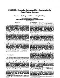
and determine the proportion of samples in each grid cell to produce the transition probability P (t0k |tk ) of the target. Fig. 4 shows the transition probability distribution of a target that is located at (xt−1 , yt−1 ) = (5, 5) with µv = 2 cells per time step and µd = 45◦ . The probability distribution of the neighboring locations that the target will move to in time step t is shown as black dots. Since the possible locations, directions, and velocities of the target are finite, we can pre-compute the transition probabilities of the target and store them off-line. This helps to reduce the on-line policy computation time, as discussed in Theorem 2.
4.4
Objective/Reward Function R
The advantage of using MDPs in surveillance systems is that any high-level surveillance goal can be defined formally using a real-valued objective/reward function. In this work, the goal of the surveillance system is to maximize the number of observed targets with a guaranteed resolution. Supposing the states of all targets are known, such a goal can be achieved by defining a reward function
T HEOREM 1. If (1) holds, then computing policy π ∗ (5) for a given state S incurs O(|A||T |m) time.
Y
Transition probability distribution for target
Target’s location at (5,5)
X
Figure 4: Transition probability distribution of a target. that measures the total number of targets lying within the fov of any of the active cameras: m X e k , C) R(S) = R((T, C)) = R(t (3)
To improve the real-time computation of policy π ∗ , the values of Ve (tk , C 0 ) (8) for all tk ∈ T and C 0 ∈ C n can be pre-computed and stored off-line. To do this, the values of P (t0k |tk ) for all tk , t0k ∈ T have to be pre-computed first, which incurs O(|T |2 ) time. The e 0k , C 0 ) for all t0k ∈ T and C 0 ∈ C n also have to be values of R(t pre-computed, which incurs O(|T ||C|n ) time. Consequently, the values of Ve (tk , C 0 ) (8) for all tk ∈ T and C 0 ∈ C n can be precomputed in O(|T |2 |C|n ) time. Hence, the total off-line computation time is O(|T |2 |C|n ). The on-line computation time to derive policy π ∗ can then be reduced to O(|A|m), which includes the time taken to look up the values of Ve (tk , C 0 ) for m targets (7) and over |A| possible joint actions (5). The result below summarizes the computation time incurred by the on-line and off-line processing steps: T HEOREM 2. If (1) holds, then computing policy π ∗ (5) for a given state S incurs off-line computation time of O(|T |2 |C|n ) and on-line computation time of O(|A|m).
k=1
�
1 if target k’s location lies in f ov(C), (4) 0 otherwise; Sn where f ov(C) = i=1 f ov(ci ) denotes a set of target locations in the environment, each of which lies within the fov of at least one active camera when the cameras are in state C. So, if the location of target k lies within f ov(C), then it is guaranteed to be observed at a predefined image resolution, as discussed in Section 4.1, and e k , C) = 1 results. R(t
e k , C) = R(t
4.5
Policy Computation
The states of the targets in the next time step are uncertain due to stochasticity of their motion. Therefore, the optimal policy π ∗ has to instead maximize the expected total number of targets that lie within the fov of any of the active cameras in the next time step: π ∗ (S) = π ∗ ((T, C)) = arg max V (T, C, A)
(5)
A∈A
X
V (T, C, A) =
R((T 0 , C 0 )) P (T 0 |T )
(6)
T 0 ∈T m
where T 0 and C 0 are, respectively, the joint states of the targets and active cameras in the next time step. The next joint state C 0 of the cameras can be determined deterministically from their current joint state C and action A using the function c0i = execute(ci , ai ) for i = 1, . . . , n (Section 4.2). Computing the policy π ∗ (5) for a given state S incurs O(|A||T |m ) time, which is exponential in the number m of targets. Its time complexity can be significantly reduced by exploiting the inherent structure of our surveillance problem, in particular, the conditional independence property in the transition model of the MDP (Section 4.3). As a result, the value function V (6) can be reduced to m X
Ve (tk , C 0 )
(7)
e 0k , C 0 ) P (t0k |tk ) . R(t
(8)
V (T, C, A) =
k=1
Ve (tk , C 0 ) =
X t0k ∈T
For a detailed derivation of (7), see Appendix A. Computing the policy π ∗ for a given state S consequently incurs linear time in the number m of targets, as shown in the result below:
5.
EXPERIMENTS AND DISCUSSIONS
In this section, we present empirical evaluation of our MDPbased approach for maximizing the number of targets observed by active cameras. Our proposed approach is simulated in Player/Stage simulator [7] to perform extensive experimentations and implemented using real AXIS 214 PTZ cameras to demonstrate its feasibility in real surveillance system. Before describing them, it is important to point out that there is no standard benchmark surveillance environments and datasets for active camera networks to compare our proposed approach with the other systems in the literature (e.g., [9, 13, 14]). While the primary criterion of these systems is to minimize the uncertainty of targets’ locations, our objective function is to maximize the number of targets observed in high-resolution images (see Table 1). These existing systems use heuristic approaches that can optimize only their respective objective function and cannot be used for other objective functions. These systems also suffer from scalability issue when the number of targets is increased. Furthermore, the optimization frameworks of these existing systems determine the cameras’ actions (or schedule the cameras) for the current time step based on the current locations of the targets. In contrast, our approach determines the cameras’ actions for the current time step based on the expected locations of the targets in the next time step (see (7) and (8)). This makes our approach perform better than the existing methods in maximizing the number of observed targets. Our MDP-based approach is empirically compared with the following existing heuristic methods: • Krahnstoever’s (Krahns) Approach: The work of [9] provided an optimization method to capture high-resolution images of a single target. It schedules the tasks for active cameras based on the location of the targets in the current time step and assumes that the targets will not move out of the fov within the short duration; • Systematic (Sys) Approach: The active cameras pan automatically in a round robin fashion such that every camera pans to each of its states for a finite duration; • Static (Stat) Approach: The active cameras are fixed at specific states such that they can cover maximum area to get high-resolution imageries of the targets. Our approach and the above heuristic methods are evaluated using the following performance metric: P ercentObs =
τ 100 X i Mobs τ Mtot i=1
camera 4 camera 2
camera 1
camera 3
camera 4
camera 3 camera 1
camera 2
Figure 5: Setups of corridor and hall environments.
where τ (i.e., set to 100 in simulations) is the total number of time i steps taken in our experiments, Mobs is the total number of targets observed by the active cameras at a given time step i, and Mtot is the total number of targets present in the environment. That is, the P ercentObs metric averages the percentage of targets being observed by the active cameras over the entire duration of τ time steps. We will first discuss the environmental setup for the simulated experiments and analyze the experimental results. Then, we will show the results of the real camera experiments. Interested readers can view our demo video1 .
5.1
Simulated Experiments: Setup
In Player/Stage simulator, we have designed an active camera model with functionalities to simulate real active cameras by configuring the number of states across pan angles, as discussed in Section 4.1. The targets’ motion are generated in Player/Stage simulator based on velocity-direction motion model (see (2)), which resembles real human motion in surveillance environment. The locations of the targets are determined by a static camera, which is the simulator itself. We have conducted our experiments for two environmental setups (Fig. 5): corridor and hall. The sizes of the corridor and hall environments are, respectively, 40 × 5 grid cells and 20 × 10 grid cells such that |Tl | = 200. The size of a grid cell in the simulator is approximately mapped to 1 m2 in real world. We have used up to n = 4 active cameras with |C| = 3, 5, and tested up to m = 50 targets. We have also conducted experiments for the camera resolutions |f ov(ci )| ≈ 25, 16 by reducing the size of the camera’s fov polygon in the simulator. The set f ov(ci ) of target locations that are observed by each active camera is determined by calibrating the active cameras in each of its state.
5.2
Simulated Experiments: Results
Figs. 6 and 7 show the performance of our MDP-based approach for corridor and hall setups with n = 4, |Tl | = 200, target’s velocity v = 3 cells per time step, and with varying m, |f ov(ci )|, |C|, and sizes of clusters of targets that follow the Poisson distribution (λ = 3). The rest of this subsection describes the observations from our experiments. Our MDP-based approach performs better for any of the target’s velocity v = 1, 2, 3 cells per time step. This is because the cameras are controlled based on the predicted locations of a target by matching its corresponding transition probabilities with respect to its observed state. It can be observed from the experiments that the performance of MDP is more superior than the other approaches when (a) the velocity of the targets is higher, (b) the targets move in clusters, and (c) when the resolution of the cameras is increased (i.e., |f ov(ci )| is decreased). This is because when the velocity of the targets is high (i.e., v = 2.5, 3 cells per time step), all the targets will almost certainly move out of the fov’s of the cameras in Krahns approach as the cameras are controlled based on 1
http://www.comp.nus.edu.sg/∼lowkh/camera.html
the current location of the targets, hence producing worse performance (see Figs. 6a and 7a). When the targets move in clusters, then the Krahns approach suffers even more performance degradation because it has high tendency to lose clusters of targets. On the other hand, since the MDP has the correct transition model, it gives superior performance even when the targets move in high velocity. By increasing the resolution of the active cameras (i.e., by reducing |f ov(ci )| ≈ 25 to 16), it can be observed that the MDP performs much better when compared to the Krahns approach (Figs. 6c, 6d, 7c, and 7d). This is because when the targets are moving at a velocity of v = 3 cells per time step and are observed at higher resolution (i.e., |f ov(ci )| is smaller), the chance of losing the targets is high when the cameras are controlled based on current observed locations of the targets. Since MDP has transition model that predicts the next locations of the targets, it outperforms the other approaches when the targets are clustered and the resolution of the cameras is high. The Sys and Stat approaches perform worse in almost all cases except when |f ov(ci )| ≈ 16 (Figs. 6c, 6d, 7c, and 7d) where the Sys approach performs better than Krahns approach. This is due to the fact that the cameras are controlled independently of the targets’ information in both Sys and Stat approaches. This shows that the targets’ information (e.g., location, direction, etc) play a vital role in achieving high-quality surveillance. But, when |f ov(ci )| ≈ 16, the Sys approach performs slightly better than Krahns because the chance of targets moving out of the fov is higher in Krahns approach if the velocity of the targets is v = 3 cells per time step and the fov is reduced to |f ov(ci )| ≈ 16. In all cases, the MDP outperforms the Sys and Stat approaches. When the number of states of each camera is increased from |C| = 3 (Figs. 6c and 7c) to |C| = 5 (Figs. 6d and 7d), the performance improves because more targets can be observed due to the additional camera states. The MDP-based approach performs better than the other approaches even when the transition model is inaccurate. This is tested by keeping the velocity of the targets moving at v = 3 cells per time step and matching the transition probabilities computed with velocities v = 2, 2.5, 3 cells per time step (Figs. 6c, 6d, 7c, and 7d). The performance of MDP computed with inaccurate transition probabilities is still much better than the other approaches. This is because the reward function is optimized with respect to the expected locations of the targets. When the number of cameras is increased from n = 2, 3 to 4, the increase in performance of MDP is much better than the other approaches for m < 10 targets and comparable to (if not better than) other approaches for m > 10. This is because the prediction capability of our approach outperforms the other approaches with every addition of a new camera. The graph with increasing number of cameras is not shown here due to space limitation. From these observations, we find that our MDP-based approach performs better than the other tested approaches in all the cases due to its prediction capability. Specifically, it outperforms Krahns approach when the velocity of the targets and the resolution of the cameras are high.
5.3
Real Experiments
We have conducted real experiments with n = 3 AXIS 214 PTZ cameras to monitor up to m = 6 Lego robots (targets) in an environment with the size of |Tl | = 11 × 9 grid cells. The size of each grid cell is 0.5 m2 . Each camera has |C| = 3 states. The states of the cameras are determined such that all the cells of the environment can be observed at high resolution by at least one camera. Given any joint state C of the cameras, only a subset of cells in the environment can be observed by these cameras, i.e., f ov(C) ⊂ Tl .
Krahns Sys Stat
PercentObs
75
85 80
PercentObs
80
70 65 60 55
75
MDP(v=3)
80
MDP(v=2)
Krahns Sys Stat
75
MDP(v=2.5)
70
MDP(v=3)
70 65 60 55
50
50
45
45
40
85
90
(a) 0
10
20
m
30
40
40
50
65
PercentObs
95
MDP(v=3)
85
PercentObs
90
Krahns Sys Stat
60 55 50 45 40 35 30
(b) 0
10
20
m
30
40
50
(c) 0
10
20
m
30
40
50
90 85 80 75 70 65 60 55 50 45 40 35 30 25 20 15
MDP(v=2) MDP(v=2.5) MDP(v=3) Krahns Sys Stat
(d) 0
10
20
m
30
40
50
Figure 6: Graphs of P ercentObs vs. number m of targets for corridor setup: (a) non-clustered targets with |f ov(ci )| ≈ 25 cells, |C| = 3 and clustered targets with (b) |f ov(ci )| ≈ 25 cells, |C| = 3, (c) |f ov(ci )| ≈ 16 , |C| = 3, (d) |f ov(ci )| ≈ 16 , |C| = 5.
75
PercentObs
PercentObs
80
70
70 65 60
65
MDP(v=3)
70
MDP(v=2)
70
MDP(v=2)
Krahns Sys Stat
65
MDP(v=2.5)
65
MDP(v=2.5)
60
MDP(v=3)
55
45 40 35
55 50
50 45
(a) 0
10
20
m
30
40
50
45
20
m
30
40
50
15
40 35
20
20
(b) 10
45
25
25
0
Krahns Sys Stat
50
30
30
55
MDP(v=3)
55
Krahns Sys Stat
50
60
60
PercentObs
Krahns Sys Stat
85
75
75
75
MDP(v=3)
90
PercentObs
95
(c) 0
10
20
m
15
30
40
50
10 0
(d) 10
20
m
30
40
50
Figure 7: Graphs of P ercentObs vs. number m of targets for hall setup: (a) non-clustered targets with |f ov(ci )| ≈ 25 cells, |C| = 3 and clustered targets with (b) |f ov(ci )| ≈ 25 cells, |C| = 3, (c) |f ov(ci )| ≈ 16 , |C| = 3, (d) |f ov(ci )| ≈ 16 , |C| = 5. This makes the problem challenging for the active cameras to maximize the number of observed robots. We have a static camera that can track these robots based on OpenCV Camshift tracker. The static camera is calibrated using [17] to obtain the approximate locations of the robots at every time step. The direction and velocity of the robots are determined based on their previous and current locations. The f ov(C) is determined by calibrating the active cameras in each of its state and determining the grid cells of the environment in which the robots can be observed at a high resolution. We guarantee the resolution of the robots that are observed by the active cameras to be approximately more than 40 × 40 pixels. We pre-computed the transition probabilities of an individual target for all possible locations, directions, and velocities v = 1, 2 cells per time step. The robots are moved based on the velocity-direction motion model and are programmed to turn back or stop when they hit the wall or cross other robots. Each robot is initialized with a Camshift tracker in the static camera and is tracked to get its approximate 3D location, direction, and velocity. We have tested our implementation up to m = 6 robots by making one of the robots static. It can be observed that cameras 2 and 3 coordinate to observe the brown static robot (Fig. 8). Camera 2 pans to another state (see bottom two rows of Fig. 8) only when camera 3 takes over the observation of the static target (see top two rows of Fig. 8). This static target can be replaced by a portion of the surveillance environment like the entrance/exit or reception where we need to pay more attention. Table 2 shows the P ercentObs performance for the real experiments over τ = 50 time steps. Our proposed approach has some limitations: (a) only when the observations from static cameras are near-deterministic (i.e., with the help of overhead static cameras), our proposed approach is expected to perform well; (b) MDP observes its targets less well when their motion is more uncertain. In our future work, we will include an observation model to handle location uncertainty due to static cameras, which results in a Partially Observable Markov Decision Process framework. We will also look into deploying active cameras with a team of mobile robots [10, 11] for tracking and surveillance of mobile targets.
Table 2: Performance for real experiments. m 1 2 3 4 5 6 P ercentObs 99.2 97 95.3 93.5 88 85.1
6.
CONCLUSION
This paper describes a novel decision-theoretic approach to control and coordinate multiple active cameras for observing a number of moving targets in a surveillance system. Specifically, it utilizes the Markov Decision Process framework, which accounts for the stochasticity of targets’ motion via a probabilistic motion model and addresses the trade-off by maximizing the expected number of observed targets with a guaranteed resolution via stochastic optimization. The conditional independence property, which is inherent in our surveillance problem, is exploited in the transition model of the MDP to reduce the exponential policy computation time to linear time. As shown in simulations, our approach can scale up to 50 targets in real time. We have also implemented our proposed decision-theoretic approach using real AXIS 214 PTZ cameras to demonstrate its feasibility in real surveillance system.
7.
REFERENCES
[1] AXIS 232D+ Network Dome Camera datasheet (http://www.axis.com). [2] J. Ai and A. A. Abouzeid. Coverage by directional sensors in randomly deployed wireless sensor networks. J. Comb. Optim., 11(1):21–41, 2006. [3] S. Banerjee, A. Chowdhury, and S. Ghosh. Video surveillance with PTZ cameras: The problem of maximizing effective monitoring time. In K. Kant, S. V. Pemmaraju, and K. M. Sivalingam, editors, ICDCN 2010, volume 5935 of LNCS, pages 341–352. Springer-Verlag, 2010. [4] A. N. Belbachir, editor. Smart Cameras. Springer, 2010. [5] C. Costello and I.-J. Wang. Surveillance camera coordination through distributed scheduling. In Proc. CDC, 2005.
camera 2
camera 3
static camera
at time = 58sec
at time = 40sec
at time = 20sec
camera 1
Figure 8: Results of real experiments: columns 1 to 3 show the high-resolution images of Lego robots captured by cameras 1, 2, and 3 while column 4 shows the targets’ trajectories tracked by the static camera. [6] H. El-Alfy, D. Jacobs, and L. Davis. Assigning cameras to subjects in video surveillance systems. In Proc. ICRA, 2009. [7] B. P. Gerkey, R. T. Vaughan, and A. Howard. The Player/Stage project: Tools for multi-robot and distributed sensor systems. In Proc. ICAR, pages 317–323, 2003. [8] C.-M. Huang and L.-C. Fu. Multitarget visual tracking based effective surveillance with cooperation of multiple active cameras. IEEE Trans. Syst., Man, Cybern. B, 41(1):234 –247, 2011. [9] N. Krahnstoever, T. Yu, S.-N. Lim, K. Patwardhan, and P. Tu. Collaborative Real-Time Control of Active Cameras in Large Scale Surveillance Systems. In Proc. M2SFA2, 2008. [10] K. H. Low, W. K. Leow, and M. H. Ang, Jr. Task allocation via self-organizing swarm coalitions in distributed mobile sensor network. In Proc. AAAI, pages 28–33, 2004. [11] K. H. Low, W. K. Leow, and M. H. Ang, Jr. Autonomic mobile sensor network with self-coordinated task allocation and execution. IEEE Trans. Syst., Man, Cybern. C, 36(3):315–327, 2006. [12] V. P. Munishwar and N. B. Abu-Ghazaleh. Scalable target coverage in smart camera networks. In Proc. ICDSC, 2010. [13] F. Qureshi and D. Terzopoulos. Planning ahead for PTZ camera assignment and handoff. In Proc. ICDSC, 2009. [14] E. Sommerlade and I. Reid. Probabilistic surveillance with multiple active cameras. In Proc. ICRA, 2010. [15] C. Soto, B. Song, and A. K. Roy-Chowdhury. Distributed multi-target tracking in a self-configuring camera network. In Proc. CVPR, pages 1486–1493, 2009. [16] M. T. J. Spaan and P. U. Lima. A decision-theoretic approach to dynamic sensor selection in camera networks. In Proc. ICAPS, pages 279–304, 2009. [17] R. Y. Tsai. An efficient and accurate camera calibration
technique for 3D machine vision. In Proc. CVPR, 1986. [18] P. Viola and M. J. Jones. Robust real-time face detection. IJCV, 57(2):137–154, 2004.
APPENDIX A.
PROOFS
Derivation of Equation 7 The value function V (6) is given by V (T, C, A) X = R((T 0 , C 0 )) P (T 0 |T ) T 0 ∈T m
=
= =
m X
X
=
R(t0k , C 0 )
t01 ∈T ,...,t0m ∈T k=1 m X X R(t0k , C 0 ) k=1 t0 ∈T k m X X
m Y
P (t0i |ti )
i=1
P (t0k |tk )
X
Y
0 ∈T m−1 T−k
i6=k
P (t0i |ti )
R(t0k , C 0 ) P (t0k |tk )
k=1 t0 ∈T k m X
Ve (tk , C 0 )
k=1 0 where T−k = (t01 , . . . , t0k−1 , t0k+1 , . . . , t0m ). The second equality is obtained using (1) and (3). The fourth equality follows from X Y X 0 P (t0i |ti ) = P (T−k |T−k ) = 1 . 0 ∈T m−1 i6=k T−k
0 ∈T m−1 T−k