Orthogonal En/Decoders for Truly Asynchronous Spectral Amplitude Encoded OCDMA B. Huiszoon, L. Bakker, H. de Waardt, G.D. Khoe, E.R. Fledderus and A.M.J. Koonen COBRA Inter-University Research Institute Eindhoven University of Technology, P.O. BOX 513, 5600 MB EINDHOVEN, The Netherlands Email:
[email protected]
Abstract— In this paper, theoretical results are presented on the modular construction of tree and cascade encoders/decoders of any size for truly asynchronous and orthogonal spectral amplitude encoded OCDMA. Three modular building blocks are proposed and described in detail. The tree structure is introduced that enables parallel code processing with a single device. The orthogonality of the code set is evaluated whereafter a revised construction method is proposed. Analysis and simulation confirm that a tree constructed via this method is orthogonal.
I. I NTRODUCTION Optical Code Division Multiple Access (OCDMA) has gained serious interest by researchers worldwide [1,2]. Attractive features of an OCDMA transmission system are high resilience against eave dropping and interference. Inherently it is a very secure technique of transmitting data. As research matures, multiple access by code increasingly becomes a third option next to time and wavelength. One of the applications of OCDMA is optical communication on Passive Optical Networks (PONs). OCDMA has a powerful natural fit on PON because both are based on broadcast-and-select. As such optimal sharing of optical medium and carrier is obtained. Optical fiber is expected to eventually replace the existing nonfiber based fixed access networks. A promising architecture herein is PON [3]. Using OCDMA on multiple wavelength channels in a PON offers huge bandwidths to a large number of subscribers for reduced infrastructure costs. Many flavors exist in optical CDMA which are generally distinguished by source (coherent/in-coherent) and domain (time/frequency) [4]. In most coherent systems short pulses are used which require expensive sources. We consider spectral amplitude coding of a low-cost incoherent source. This is therefore referred to as Spectral Amplitude Encoded OCDMA (SAE OCDMA). Previous work demonstrated SAE OCDMA in a free space, optical fiber or integrated optics setup [5-7]. The integration of optics is key for large-scale mass production to introduce optical technologies in the access network. A passive integrated component in [7] was used on a point-topoint SAE OCDMA transmission link. Point-to-multi point communication is made in a PON between a Central Office (CO) and multiple end users. Parallel processing of up and downstream data is required at the CO for truly asynchronous medium access. In this paper, a single integrated device, referred to as tree, is presented that has such functionality. Its cost-efficient design
only uses a single input to all-optically generate or process a multitude of spectral codes1 . The processing power, expressed in the number of codes it generates/processes, can be easily increased because of a modular construction. Next to the design and model of an essential building block of the tree, the manuscript elaborates on code orthogonality and in particular the orthogonality of the codes generated/processed by the tree structure. Based on the evaluation a modified generalized design of an orthogonal tree is proposed. Its correct operation is confirmed by analysis and simulation. Firstly previous work on spectral amplitude encoded OCDMA is reviewed in Section II with a focus on integrated solutions. Then three modular building blocks are introduced in Section IV. Easy construction of cascade and tree structures is discussed in the same section. Section IV focusses on code orthogonality. A revised design method is proposed to construct orthogonal trees. Section V analyses the transfer functions of various orthogonal trees. Section VI shows simulation results that confirm proper operation of the orthogonal tree. Finally, Section VII concludes the manuscript whereafter the acknowledgements and references are given. II. S PECTRAL A MPLITUDE E NCODED OCDMA Spectral amplitude encoding of incoherent optical sources was first proposed in [5]. In this work a spatially patterned amplitude mask filters an incoherent optical spectrum which is launched into free space. After the spectrum has passed through the mask, the fringe pattern, e.g. A(ω), is visible in the spectrum. The optical spectrum is then said to be encoded by the encoder and ready to represent a subscriber on an OCDMA network. Each subscriber is identified by its uniquely patterned amplitude mask. They all send their information asynchronously in the same wavelength band thus the properties of the mask have to ensure orthogonality between the user channels. Therefore each mask pattern is arranged according to a particular code, e.g. the well-known m or Hadamard codes. At the transmitter side an incoherent source, e.g. a Light Emitting Diode (LED), is directly modulated by an Amplitude Shift Keyed (ASK) data sequence. This modulated optical spectrum is then led through the mask. At the receiver side the optical signal is launched into a decoder which is constructed 1 NL
patent application 1031833 by Eindh. Univ. of Tech., 17th May 2006
by a spatially patterned mask, e.g. B(ω), and its complementary copy denoted as B(ω). A code match between encoder and decoder, A(ω) = B(ω), results in maximum optical power at the output of B(ω) and minimum optical power at the output of B(ω). No code match leads to average optical power. The outputs of the decoder masks are connected to a balanced receiver. The total detected current at the output of the balanced receiver is given by Ibal = Idiode,1 − Idiode,2 . As such, this dual filter setup plus the balanced receiver maximizes the auto-correlation for a code match and minimizes the crosscorrelation in case of no match. The original ASK data can then be retrieved. One way to enhance the use of the balanced receiver is to also have the complementary copy A(ω) available at the transmitter. In such a way, the binary data sequence can be represented by A(ω) and A(ω). If the proper mask is set at the decoder, the received optical power at the inputs of the balanced receiver varies between maximum and minimum value along with the transmitted sequence. The modulation format of such a system is generally referred to as Spectral Shift Keying (SSK). Polar signaling is achieved that has a 3 dB Signal-to-Noise Ratio (SNR) advantage over unipolar signaling [8]. Only with such an SSK setup full rejection of multiple user interference can be achieved [9]. However, a drawback of the system is its free space setup. It is bulky and expensive and, more importantly, difficult to miniaturize. A significant improvement to the setup was made in [7] where a low complexity integrated solution based on MachZehnder Interferometers (MZIs) was proposed. The MZI is a planar waveguide device that is easily constructed by 2 × 2 3 dB Multi Mode Interference (MMI) couplers and waveguides. The behavior of an MMI can be explained by the relation between its two inputs and two outputs (hence 2 × 2). A π/2 phase shift is applied to one of the output fields if the optical power is launched in one of the inputs. Thus a cascade of two MMIs results in a device that causes complete constructive interference at one output and complete destructive interference at the other output because of the accumulated π phase difference. If the input is changed, the complementary spectra swap position at the output. A periodic interference pattern is generated when a path length difference is applied between the two waveguides. This is referred to as the Free Spectral Range (FSR) of the MZI. As such, two complementary fringe patterns, e.g. C(ω) and C(ω), are available by only using a single device. A second orthogonal set of complementary spectra can be generated by applying an extra π/2 phase shift in one of the arms. By doing so the transfer function is transformed from cosine to sine. The orthogonal sets of complementary spectra are denoted as phase codes. The phase codes are binary identified by a 0 when the extra phase shift is absent and by a 1 when the extra phase is present. The resulting binary word is referred to as a Phase Code Identifier (PCI). The phase codes of an integrated MZI can be used asynchronously on a network with two subscribers. The same device is placed at the transmitter and receiver side as en-
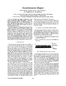
coder and decoder. At the transmitter side two configurations are possible to perform SSK, namely with a balanced transmitter placed in front of the inputs or with an electrooptical port switch placed behind the outputs. This reflects an SSK OCDMA network with integrated MZI-based encoding/decoding in its simplest form. It is clear that a single MZI can only generate two phase codes. A tunable (0, π/2) phase shifter allows a selection between the subscribers at a central office. The number of phase codes or cardinality of the MZI is increased by cascading another 3 dB MMI coupler. Similarly the waveguides that connect the third MMI to the MZI have a path length difference and a tunable phase shifter. Such a two-stage cascade is shown in Fig. 1.
Fig. 1.
Two-stage cascade structure
The device has a cardinality of four with the following PCIs: 00, 01, 10 and 11. For example, a subscriber communicates via PCI 01 if phase shifter φ1 and φ2 in Fig. 1 are set to 0 and π/2. III. M ODULAR C ONSTRUCTION OF C ASCADE AND T REE E NCODERS /D ECODERS The state-of-the-art has shown MZI-based cascade encoders/decoders which can address a single subscriber once a phase code is set. A different phase code has to be set to address another subscriber. Therefore a cascade structure only allows serial code processing. This implies that M cascade structures are required at, for example, the CO of a PON to have asynchronous communication with M end users. Using an M -stage tree enables to do this but then with a single device. Besides the application in a PON the tree can also be used to create multiple channels between two single subscribers to increase the total capacity similar to Multiple Input Multiple Output (MIMO) communication systems. In this section three building blocks are presented to modularly construct the cascade and tree encoder/decoder structures as discussed before. The modular blocks are defined as the 2 × 2 3 dB MMI coupler, a 2 × 2 Cascade Element (CE) and a 2 × 4 Crossed Tree Element (XTE). The transfer functions of all three building blocks are discussed whereafter an important characteristic of the XTE is explained in more detail. The schematic drawings of the MMI, CE and XTE are shown in Fig. 2. Equation (1) and (2) describe the transfer functions MMMI and MCE via the propagation matrix [10] · ¸ 1 1 j MMMI = √ (1) 2 j 1
input of the coupler section according to 0 0 1 0 Mi = 0 0 0 1
(4)
The coupler section matrix is then described by · ¸ MMMI 0mn Mm44 = 0mn MMMI
Fig. 2. Three modular blocks to construct SAE OCDMA encoders/decoders
MCE
= =
· ¸ hϕ (φ) MMMI · 1 · ¸ 1 hϕ (φ) j √ 2 jhϕ (φ) 1
(2)
with hϕ (φ) = e−j(ϕ+φ) , ϕ = 2πf · neff · ∆L/c, f the optical frequency, neff the effective refractive index of the waveguide, ∆L the path length difference, c the speed of light and j the imaginary unit (j 2 = −1). The phase shifter φ either set to 0 or π/2 according to the position of the CE in the cascade with respect to the PCI. Note the frequency dependency of the phase shift ϕ and the frequency independency of phase shift φ. A one-stage cascade is then constructed by an MMI and a CE with the propagation matrix MC1 as follows MC1
= =
MCE · MMMI · ¸ 1 hϕ − 1 jhϕ + j 2 jhϕ + j −hϕ + 1
where MMMI was defined in (1), and 0mn is a m × n zero matrix with m = 2 and n = 2. The optical fields in two of the four waveguides are then delayed by ∆L and are passed through either phase shifter φ1 or φ2 . The path length differences and phase shifters can be randomly positioned in the XTE. The only requirement is that a delayed and non-delayed optical field interfere at the final MMI. The specific interconnection scheme of the waveguides in Fig. 3 is given by hϕ (φ1 ) 0 0 0 0 0 1 0 Md = (6) 0 hϕ (φ2 ) 0 0 0 0 0 1 with hϕ (φ) as in (2) and the phase shifters φ1 or φ2 set to 0 or π/2 according to the position of the XTE in the tree with respect to the PCI. The propagation matrix of the XTE building block is calculated by MXTE
= =
(3)
The propagation matrix MC2 is then easily calculated by MC2 = MCE · MC1 , until MCN for an N -stage cascade. The derivation of the propagation matrix MXTE is more complicated than MCE . Therefore subsections have been defined which are shown in Fig. 3.
Mm44 · Md · Mm44 · Mi jhϕ (φ1 ) −1 1 −h j ϕ (φ1 ) . h (φ ) j 2 ϕ 2 jhϕ (φ2 ) 1
MT1
=
MXTE · M MMI jhϕ (φ1 ) − j µ ¶3 −hϕ (φ1 ) − 1 1 √ 2 hϕ (φ2 ) − 1 jhϕ (φ2 ) + j
−hϕ (φ1 ) − 1 −jhϕ (φ1 ) + j (8) jhϕ (φ2 ) + j −hϕ (φ2 ) + 1
The propagation matrix MT2 is given by · ¸ MXTE 0mn MT2 = · MT1 0mn MXTE
Subsections of the XTE building block
The interconnection matrix is defined to connect the two outputs of the preceding element to the second and fourth
(7)
A one-stage tree is then constructed by an MMI followed by an XTE which results in the propagation matrix MT1
=
Fig. 3.
(5)
(9)
with m = 4 and n = 2. Equation (9) can be easily expanded for N -stage trees. The crossover between the upper and lower branch of the XTE is mandatory to obtain the same functionality in a tree as in a cascade. Without crossover the XTE contains two individual MZIs. Such a building block can be used to construct a multi/demultiplexer and is therefore referred to as
Multi/Demultiplexer Element (MDE). The propagation matrix, MMDE , is as follows jhϕ (φ1 ) + j 0 1 −hϕ (φ1 ) + 1 0 (10) MMDE = 0 jhϕ (φ2 ) + j 2 0 −hϕ (φ2 ) + 1 As shown, the MDE modifies the input fields independently which is not the case for the XTE. This leads to an important difference between MDE and XTE if the injected optical power is not uniformly distributed over a particular spectral range, e.g. one FSR period. That situation occurs when a set of complementary spectra is injected. Crossing over the waveguides of the two arms in the XTE recovers optical components which are filtered or attenuated in the MDE. Cascading MDEs results in narrow filtering around parts of the original spectrum. Cascading XTEs results in fringe patterns at the outputs which remain to have the spectral width of the input signal. Thus if no interference history is present at the input the MDE and XTE give a similar response. The first stage of an N -stage tree can therefore be either of both. The frequency response of the MDE and XTE has been simulated. The power spectral density of the transmitter is constant for one FSR period but equals zero for all other frequencies. Then, the square of the absolute value is taken of the transfer function to derive the power transfer function. The results in Fig. 4 clearly show the difference between trees constructed by MDEs and XTEs already at the second stage. 0
Output power [dB]
−10
XTE
−20
MDE
NXTE = log2 (Cp ) ; NXTE ∈ N
−30
−40 0
0.2
0.4
with ω1 and ω2 as the boundaries of the encoded spectrum, sk and sl as the spectral intensity transfer function of encoder k and decoder l, and B as a power value greater than zero. Typically ω1 and ω2 are equal to one FSR period. Thus a match between encoder and decoder leads to maximum correlation whereas no match gives zero. Two factors determine the orthogonality of the phase codes namely the multiplication factors applied to the path length differences of each stage and the PCIs. In original work of [7], the cardinality increases by 2N with N the number of stages, and the path length difference of each stage is the double of the path length difference of the previous stage. The study in [11,12] mathematically proved that these two settings do not provide a full set of phase codes. Improved sets of multiplication factors and PCIs have been proposed which are easily implemented in an N -stage cascade or tree. However a strict design constraint has been derived which has significant implications on the construction of encoder/decoder structures. It has been shown that only an increase in even stages doubles the cardinality. Thus the length of the PCIs has to be even in order to have an orthogonal code set. For a cascade the design can be easily adopted but for a tree it is more complicated. As a result of the constraint, a tree built solely with XTEs is not efficient because it also generates non-orthogonal spectra. For example, a two-stage tree has a cardinality of four. The cardinality is doubled to eight only when the PCI has length four. If a tree is constructed only with XTEs, a PCI of length four leads to sixteen generated sets of spectra which can not be orthogonal. Therefore the trees have to be constructed by MMI, XTE and also CE blocks. The XTEs are used until the structure reaches the correct cardinality and the CEs are then used to extend the tree up to the correct length of the PCI. This is of course only true for trees larger than two stages. The amount of XTE stages of the modified trees is given by the number NXTE according to
0.6
0.8
1
Normalized Free Spectral Range
(12)
where Cp is the phase code cardinality. Following the design rules, the amount of CE stages is then simply calculated by NCE = NXTE − 2. The total number of stages N equals to NXTE + NCE . The modular construction of various trees up to a cardinality of eight is shown in Fig. 5, including the nonorthogonal three stage tree.
Fig. 4. Power transfer function of branch four of a two-stage XTE and MDE
IV. M ODULAR C ONSTRUCTION OF O RTHOGONAL T REE E NCODER /D ECODER A detailed study towards orthogonality in cascade structures has been made by [11,12]. The following expression has to be met for full orthogonality between phase codes Z ω2 0 if k 6= l sk (ω)sl (ω)dω = (11) ω1 B if k = l
V. E VALUATION OF O RTHOGONAL T REE E NCODER /D ECODER In this section, the propagation matrix is evaluated of trees which comply with the design rules given in the previous section. It is shown that these trees have a direct relationship with cascades which also comply with the revised construction method. As such both structures generate the same phase codes. It is then said that the trees constructed via the revised method are orthogonal. The following relationship between the
with i the branch counter which is element of [1, 2, . . . , Cp ]. The coefficient wB (i) is the sum of elements of the binary representation of the number w(i) given by w(i) = Cp − i
(20)
For example, the coefficients wB (i) are shown in Table I for tree with cardinality four. TABLE I C OEFFICIENTS wB (i) FOR CP = 4
Fig. 5.
Modular construction of trees up to cardinality of eight
propagation matrices in (3) and (8) is easily derived · ¸ 1 j · MC1 MT1 = √ MC1 2
(13)
which can be rewritten as MT1 = Θ1 ⊗ MC1
(14)
where ⊗ denotes the Kronecker or direct matrix product and Θ1 is given by · ¸ 1 j (15) Θ1 = √ 1 2 Equation (14) shows that compared with a cascade a tree gives a power loss for both branches and an extra π/2 phase shift for the upper branch. The vector Θ1 is clearly the effect of the extra 3 dB couplers in a one-stage tree with respect to a onestage cascade. The optical power is split equally over the upper and lower branch of the tree and the upper branch receives the extra phase shift because of the specific interconnection of the waveguides in Fig. 2. This phase shift however has no effect on the relative phase shift between the two outputs. The phase codes of a one-stage tree and cascade are therefore equal. For two stages MT2 similarly relates to MC2 by MT2 = Θ2 ⊗ MC2 with Θ2 given by
(16)
−1 1 j Θ2 = 2 j 1
(17)
where (17) represents the effect of two consecutive extra 3 dB coupler stages. It is then easily derived that the propagation matrix of an N -stage tree relates to the propagation matrix of an N -stage cascade by MTN = ΘN ⊗ MCN where the ith element of ΘN is given by ¯s ¯ ¯ 1 ¯ ¯ ¯ wB (i) ΘN,i = ¯ ¯·j ¯ Cp ¯
(18)
(19)
i
w(i)
wB (i)
1 2 3 4
3 2 1 0
1+1=2 1+0=1 0+1=1 0+0=0
As mentioned at the start of this section, the general relationship between an N -stage orthogonal tree and an N stage orthogonal cascade in (18) shows that both structures generate the same phase codes. Therefore the correct operation of an orthogonal tree is confirmed by analysis. VI. S IMULATION R ESULTS ON O RTHOGONALITY In this section, simulation results are given which support the conclusion of the previous section. The cascade and tree structures are simulated in two different environments.The first environment calculates the analytical model as previously discussed in this paper. The second environment is Graphical User Interface (GUI)-based and has large libraries of detailed models of different components. In order to compare the GUI-based model with the analytical model, the frequency response of a two-stage tree is evaluated. The results are shown in Fig. 6(a) and 6(b). The plots show a good resemblance between both models. Moreover they correspond with the ones shown for cascade structures in [11]. The setup shown in Fig. 7 is then modelled in the GUI-based environment to evaluate the orthogonality of two different tree and cascade structures. Both designed according to the ”original” design rules or both designed according to the ”orthogonal” design rules. Fig. 7 basically shows the SSK setup as described in section II. A summary of the results is shown in Fig. 8 where the transmitted phase code is plotted versus the received output power per decoder. The upper subplot shows that a nonorthogonal set of phase codes is generated for the original work. The lower subplot, however, clearly shows a orthogonal set of phase codes is generated for the tree constructed via the revised construction method. The correct operation of an orthogonal tree is therefore confirmed by simulation. Note that the influence of phase noise and an unbalanced splitting ratio on the orthogonality has not been taken into account in this analysis.
Output power [dBm]
10 0
−10 −20 1
2
3
4
5
6
7
8
7
8
(a) Branch one and two of two-stage tree (PCI 00 and 01)
Output power [dBm]
Transmitter phase code 10 0
RxP1 RxP2 RxP3 RxP4 RxP5 RxP6 RxP7 RxP8
−10 −20 1 Fig. 8.
2
3
4
5
6
Simulated response for Cp = 8: Orig. (up), Orth. (down)
through the NRC Photonics grant. Authors also acknowledge T.C.W. Schenk for valuable comments. R EFERENCES
(b) Branch three and four of two-stage tree (PCI 10 and 11)
Fig. 6.
Simulation in GUI-based (thick) and analytical (thin) environment
Fig. 7.
Simulation setup for evaluation of orthogonality
VII. C ONCLUSIONS We have shown the results of analysis and simulation on the modular construction of tree and cascade encoders/decoders of any size for truly asynchronous and orthogonal spectral amplitude encoded OCDMA. A tree encoder/decoder has been developed to perform parallel code processing with a single device. The orthogonality of the code set produced by the tree was evaluated. This resulted in a revised construction method for orthogonal trees. The improved performance of those trees was confirmed by analysis and simulation. ACKNOWLEDGEMENTS This research is carried out in the COBRA SWOOSHING project. The Netherlands Organization for Scientific Research (NWO) is gratefully acknowledged for funding
[1] X. Wang, N. Wada, T. Miyazaki, G. Cincotti and K. I. Kitayama, “Field Trial of 3-WDMx10-OCDMAx10.71 Gbps, Truly asynchronous, WDM/DPSK-OCDMA Using Hybrid E/D Without FEC and Optical Threshold,” in Proc. OFC’06, paper PDP44. [2] V. J. Hernandez, W. Cong, R. P. Scott, C. Yang, N. K. Fontaine, B. H. Kolner, J. P. Heritage and S. J. B. Yoo, “320-Gb/s Capacity (32 Users x 10 GB/s) SPECTS O-CDMA Local Area Network Testbed,” in Proc. OFC’06, paper PDP45. [3] A. M. J. Koonen, “Fiber to the Home/Fiber to the Premises: What, Where, and When?” Proceedings of the IEEE, vol. 94, no. 5, pp. 911– 934, May 2006. [4] K. I. Kitayama, X. Wang and H. Sotobayashi, “State of the Art of OCDMA, OCDM, and OC-label Switchings,” in Proc. ECOC’04, paper Tu4.6.1. [5] D. Zaccarin and M. Kavehrad, “An Optical CDMA System Based on Spectral Encoding of LED,” IEEE Photon. Technol. Lett., vol. 4, no. 4, pp. 479–482, April 1993. [6] S. Ayotte, M. Rochette, J. Magne, L. A. Rusch and S. LaRochelle, “Experimental Verification and Capacity Prediction of FE-OCDMA Using Superimposed FBG,” IEEE/OSA J. Lightw. Technol., vol. 23, no. 3, pp. 724–731, February 2005. [7] C. F. Lam, R. Vrijen, D. T. K. Tong, M. C. Wu and E. Yablonovitch, “Experimental demonstration of spectrally encoded optical CDMA systems using Mach Zehnder encoder chains,” in Proc. CLEO’98, paper CThU4. [8] L. W. Couch, Digital and Analog Communication Systems, 5th ed. Prentice Hall, 1997. [9] L. Nguyen, B. Aazhang and J. F. Young, “All-optical CDMA with bipolar codes,” Electron. Lett., vol. 31, no. 6, pp. 469–470, March 1995. [10] B. H. Verbeek, C. N. Henry, N. A. Olsson and K. J. Orlowsky, “Integrated Four-Channel Mach-Zehnder Multi/Demultiplexer Fabricated with Phosphorous Doped SiO2 Waveguides on Si,” IEEE/OSA J. Lightw. Technol., vol. 6, no. 6, pp. 1011–1015, June 1988. [11] I. Radovanovic, “Optical Local Area Networks: New Solutions for Fiber-To-The-Desk Applications,” Ph.D. dissertation, Twente University, December 2003. [12] I. Radovanovic, L. Bakker and W. van Etten, “Improvement in Design of Mach-Zehnder En/Decoder for Implementing New Orthogonal Codes in OCDMA Systems,” in Proc. IEEE CVT Benelux Conf. ’01, pp. 234-236.