Information and Software Technology 43 (2001) 401±412
www.elsevier.nl/locate/infsof
Decomposing legacy systems into objects: an eclectic approach G. Canfora a,*, A. Cimitile a, A. De Lucia a, G.A. Di Lucca b a
b
FacoltaÁ di Ingegneria, UniversitaÁ del Sannio, Palazzo Bosco Lucarelli, Piazza Roma, 82100 Benevento, Italy Dipartimento di Informatica e Sistemistica, UniversitaÁ di Napoli ªFederico IIº, Via Claudio, 21-80125 Napoli, Italy Received 25 November 1999; revised 4 January 2001; accepted 9 January 2001
Abstract The identi®cation of objects in procedural programs has long been recognised as a key to renewing legacy systems. As a consequence, several authors have proposed methods and tools that achieve, in general, some level of success, but do not always precisely identify a coherent set of objects. We show that using an eclectic approach, where a domain expert software engineer is encouraged to tailor and combine existing approaches, may overcome the limitation of the single approaches and helps to better address the particular goals of the project at hand and the unique aspects of the subject system. The eclectic approach is illustrated by reporting experiences from a case study of identifying coarse-grained, persistent objects to be used in the migration of a COBOL system to a distributed component system. q 2001 Elsevier Science B.V. All rights reserved. Keywords: Reverse engineering; Software migration; Legacy systems; Object identi®cation
1. Introduction There is a large consensus within the software maintenance community that identifying objects in existing procedural programs is desirable. In a seminal paper, Liu and Wilde [18] state that it can facilitate acquiring a precise knowledge of the data items in a program, the ways these items are created and modi®ed, and their relations. This is one of the greatest challenges in the maintenance of existing software. Livadas and Johnson [19] suggest a number of reasons for identifying objects. These include understanding system design, testing and debugging, re-engineering from a conventional programming language into an object-oriented language, avoiding degradation of the original design during maintenance and facilitating the reuse of existing operations contained in the system. Achee and Carver [1] suggest that identifying objects can help both to extend the bene®ts of recent programming innovations to most systems currently in use and to repair the damages of extensive maintenance. Similarly, McFall and Sleith [20] indicate an objectoriented representation as a desirable target for reverse engineering procedural code because of the advantages deriving from evolving the reverse-engineered programs in an * Corresponding author. Tel.: 139-824-305804; fax: 139-824-21866. E-mail addresses:
[email protected] (G. Canfora),
[email protected] (A. Cimitile),
[email protected] (A. De Lucia),
[email protected] (G.A. Di Lucca).
object-oriented domain. Sneed and Nyary [26,27] identify objects as a part of a process to downsize large application programs from the mainframe to distributed client±server type systems. Methods to identify objects have also proven helpful in the context of legacy system migration [8]. Siff and Reps [25] identify objects with the aim of transforming monolithic programs into functionally equivalent code that makes explicit use of modules. Yeh et al. [30] discuss object identi®cation in the broader context of recovering software architectural representations from source code and Dunn and Knight [10] and Canfora et al. [5] focus on software reuse by pursuing the extraction of reusable objects from existing software systems. As a consequence of this interest, many methods and tools to identify objects in procedural programs have been proposed in the literature. Some of the object identi®cation methods are based on de®ning a model of the subject system as a graph on which notable subgraphs and/or patterns are then identi®ed [5,10,18,19,30]. A very similar approach consists of applying cluster analysis [1,13,28,29]. Other methods apply a combination of knowledge-based systems and arti®cial neural networks to the problem of identifying the objects and interpreting them, i.e. mapping application domain meanings onto the identi®ed objects [20]. Cimitile et al. [8] found the identi®cation of objects on the optimisation of certain object-oriented design metrics. Breuer et al. [4] apply formal methods to identify objects in both program code and speci®cations and to express them in
0950-5849/01/$ - see front matter q 2001 Elsevier Science B.V. All rights reserved. PII: S 0950-584 9(01)00149-5
402
G. Canfora et al. / Information and Software Technology 43 (2001) 401±412
the Z11 notation, an object oriented extension of Z. Newcomb and Kotik [22] exploit a transformation programming system to transform procedural into object-oriented programs through a comprehensive set of intermediate structures and mappings. Several authors apply mathematical concept analysis [31], a branch of lattice theory, to the problem of identifying objects [17,25,28]. Gall and KloÈsch [12] propose a distinctive approach that is not only based on the information derivable from the source code, but also integrates domain and application-speci®c knowledge to achieve the identi®cation of application-semantic objects. Most of the methods and tools proposed to identify objects have been tested in some case studies and/or pilot projects and have shown promising results. However, by no means has a single approach been shown to be able to deal with the large variety of problems that arise in real-life large-scale processes of identifying objects in legacy systems. Each legacy system presents unique aspects that require to be handled with adequate methods and tools. This makes the process of identifying objects unlikely to be fully captured in a method and automated. Every method has its own merits, but no one should be claimed as the ultimate solution to the problem of identifying objects. More properly, an eclectic approach to object identi®cation should be adopted, where a domain expert software engineer is encouraged to build the object identi®cation method most suitable to the system at hand by selecting, tailoring, and combining existing approaches. The selection of the existing approaches to combine depends on both the structural characteristics of the systems and the characteristics of the objects desired. For example, methods that work ®ne to identify persistent, coarse-grained objects may be less effective in identifying volatile, ®negrained objects. Similarly, some methods may produce good results for programs coded in languages that offer routines, scope rules, parameter passing, and return types, such as C and Pascal, and be not applicable to languages like COBOL that do not have these features. Finally, the effectiveness of a method may depend on the design rationale and design decisions made in the original development, the coding style and conventions, and the level of degradation of the original, planned structure. This calls for a framework where the different approaches are coherently described and classi®ed. Lakhotia [14] presents a uni®ed framework for clustering-based approaches. Benedusi et al. [3] de®ne the Goals-Models-Tools paradigm for selecting and combining reverse engineering tools based on the goals of the reverse engineering process. Tortorella et al. [11] propose the REP methodology to characterise the components of a software process and apply it to object identi®cation methods and tools. This paper reports an experience of applying eclecticism to identify objects in legacy code. The study was carried out on a system coded in COBOL and was aimed at the identi®cation of coarse-grained, persistent objects to be used as a basis for migration to a distributed component architecture.
The study showed that combining several object identi®cation methods and tailoring them to the characteristics of the subject system may produce objects, which contain less spurious operations, are more strictly related to the application domain, and require less human effort to understand and unravel. The problem of wrapping the resulting components and incrementally migrating them to a target architecture is out of the scope of this paper. Aversano et al. [2] discuss the issue of wrapping legacy systems to make them accessible from the Web, while a strategy to incrementally migrate wrapped components of legacy systems to an objectoriented language is presented in Ref. [6]. The remainder of the paper is organised as follows: Section 2 reviews existing object recovery methods we have used in our study. Section 3 presents an eclectic approach to apply these methods on data-intensive legacy systems. Section 4 describes the application of these methods to a COBOL software system and discusses the results. Concluding remarks and lessons learned are outlined in Section 5. 2. Methods for identifying objects in legacy systems An object is a collection of operations that share a state; the operations determine the behaviours the object exhibits, while the shared state is hidden from the outside world and is accessible only to the object's operations. In practice, most methods for identifying objects in procedural programs intend an object as a collection of global data items, which de®ne the shared state, and procedural components, which implement the operations. Depending on the particular method, data items can be either permanent data stores, such as ®les and database tables, volatile variables, and user-de®ned data types; examples of procedural components include entire programs, routines (procedures, functions, sections, paragraphs), and chunks or slices of code. Moreover, object recovery methods may only concentrate on partitioning a legacy systems into objects or they may also support the abstraction of relations between these objects. This section discusses existing object identi®cation methods we have used in our study. The discussion is organised around three classes of methods: methods that de®ne a model of the subject system in the form of a graph on which notable subgraphs are then identi®ed; methods that apply mathematical concept analysis to identify similarities among procedural components based on the data-stores they access; and methods that found the identi®cation of objects on the optimisation of selected object-oriented design metrics. These methods are ®nally classi®ed according to two dimensions: 1. the ability to identify volatile ®ne-grained objects versus the ability to identify persistent coarse-grained objects; 2. the ability to simply partitioning a legacy system into
G. Canfora et al. / Information and Software Technology 43 (2001) 401±412
P2 P3 D1
P1 P5
D2
P6 P4 P11 P10 D3 P9 P7
D4
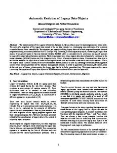
P8 Fig. 1. Strongly connected subgraphs.
objects versus the ability to abstract an architecture (i.e. relations between objects).
403
notion of coincidental and spurious connections, i.e. connections that are induced by procedural components that access the data structure of more than one object. These procedural components either implement more than one service, each service logically belonging to a different object (in this case, they induce coincidental connections), or implement system-speci®c operations (in this case, they induce spurious connections). The method proposed by Canfora et al. [5] identi®es these procedural components, by exploiting a measure of the internal connectivity of the strongly connected subgraphs and deletes them from the bipartite graph, thus allowing the decomposition of a strongly connected subgraph into more than one candidate object. For example, in Fig. 1, the procedural component P1 is likely to induce a coincidental or spurious connection; by deleting this component from the bipartite graph, the two candidate objects clustered around the data items D1 and D2 can be identi®ed. Strongly connected subgraph methods have been largely applied to programs written in languages such as Pascal, C, and FORTRAN that provide variable scope rules and routines exchanging data through parameters declared in their headings.
2.1. Notable subgraph methods
2.2. Concept analysis methods
A common approach to object identi®cation consists of de®ning a model of the subject system in the form of a (polypartite) graph that depicts some meaningful relations among procedural components and data items. Examples include the relation references between routines and global data items and the relation declares a formal parameter (or return value) of type between routines and user-de®ned data types [5,10,18,19,30]. Other approaches consider statement blocks rather than procedures as candidates for object operations [1,23]. Different cluster analysis algorithms can be used to identify groups of related components de®ning potential modules [29]. For example, some approaches use similarity measures induced by the graph and hierarchical algorithms to cluster together related procedural components [13] or data items [28]. Data mining techniques, useful for the extraction of notable patterns of information from large databases, have also been adapted to cluster together COBOL subsystems consisting of programs that use common ®les [21]. Other approaches use graph theoretical algorithms to partition the graph in notable subgraphs. A largely adopted method consists of identifying groups of procedural components and data items forming strongly connected subgraphs as the candidates for objects [10,18,19,30]. For example, Fig. 1 shows an example of bipartite graph: ellipses represent procedural components, while rectangles represent data items; two strongly connected subgraphs can be identi®ed (see the dashed rectangles in the ®gure). This method has been improved by Canfora et al. [5]: they introduce the
Recently, mathematical concept analysis [31] has been proposed as a method to identify objects and classes in existing code [17,25]. Concept analysis is more general than graph-based methods as it can capture the same kinds of relations depicted in graphs and presents several additional advantages. These include a ®ner control over the granularity of the obtained modularisation and an improved discriminatory power. Concept analysis de®nes a context as a triple C
E ; A; R; where E is a ®nite set of entities, 1 A a ®nite set of attributes, and R a binary relation on E and A. For object identi®cation, the entities are procedural components, while the attributes can be any of several properties relating procedural components to data items. Examples of attributes are: uses global variable v [17], return type is t, has arguments of type t, uses ®elds of structured type t [25]. For any set of entities E # E and attributes A # A; the common attributes of E and the common entities of A are denoted by ca(E) and ce(A), respectively. A concept is a maximal collection of entities sharing common attributes; it is de®ned as a pair C
E; A; where A ca
E and E ce
A: The set of entities is the extent of C (E ext
C), while the set of attributes is the intent of C (A int
C). In the context of object identi®cation, a concept corresponds to a possible object or class; the procedural components represent the operations while the set of data items involved in the attributes de®nes the state. The set of all concepts for a given context forms a 1
In Refs. [17,25,31], these are called objects.
404
G. Canfora et al. / Information and Software Technology 43 (2001) 401±412
0
1
2
4
C0 = ({P1, P2, P3, P4, P5, P6, P7, P8, P9, P10, P11}, ∅) C1 = ({P7, P9, P10, P11}, {D3}) C2 = ({P7, P8, P9, P10}, {D4}) C3 = ({P7, P9, P10}, {D3, D4}) C4 = ({P1, P4, P5, P6}, {D2}) C5 = ({P1, P2, P3}, {D1}) C6 = ({P1}, {D1, D2}) C7 = (∅, {D1, D2, D3. D4})
5
3
6
7 Fig. 2. A concept lattice.
complete lattice on the partial ordering relation: C
E; A if and only if ext
C1 # ext
C2 (or equivalently int
C1 $ int
C2 ). The smallest common super-concept or supremum (the largest common sub-concept or in®mum) of two concepts is obtained by intersecting their intents (their extents, respectively). Each concept in the lattice de®nes a potential object or class and relations between concepts can suggest cases of inheritance or associations between classes. For example, Fig. 2 shows the lattice derived from the context in Fig. 1. The method has given good results when applied to programs written in C [25] and Modula-2 [17]. Early applications of concept analysis to modularise COBOL programs were not successful [17]; in this study, procedural and data components consisted of COBOL sections and records, respectively. A more recent case study [28] showed that good results in decomposing large ®le records can be achieved by considering programs as entities and usage of ®le record ®elds as attributes. 2.3. Design metrics optimisation methods Cimitile et al. [8] propose a method for identifying coarse-grained objects whose state is implemented by persistent data stores. First, a static analysis of the source I
II Concept Analysis
Architecture
Design Metrics Optimisation
Objects III
Notable Subgraphs
Fine-grained Volatile
IV
Coarse-grained Persistent
Fig. 3. Classi®cation of object recovery methods.
code is performed to identify the persistent data stores used and their structure. The results are then re®ned through an analysis of the synonyms 2 and a concept assignment process. Synonymous ®les are grouped to form one object. The concept assignment process is performed to associate a concept of the application domain to each of the identi®ed objects and to aggregate data stores corresponding to the same element of the application domain. Object operations are searched for at the program level ®rst: object-oriented design metrics are used to assign programs as object operations. In particular, the assignment is made while trying to minimise the coupling between the objects. Measures of the coupling between programs and persistent data stores are computed based on the accesses that programs make to the data stores. The minimisation of the coupling between the potential objects is achieved by associating each program to the object it is most highly coupled. However, a program is assigned to an object only if it does not access other objects (exclusive coupling) or if the coupling between the program and the object is sensibly higher than the coupling between the program and any other object (predominant coupling). On the other hand, programs with a uniform distribution of coupling have to be decomposed into smaller components. The predominance of coupling is established by using a threshold value. For example, with reference to Fig. 1, the method will identify four objects, clustered around the four data items. Programs P2, P3, P4, P5, P6, P8, and P11 are exclusively coupled to one data item, while programs P1, P7, P9, and P10 access more than one data item. If the coupling measures between the program P10 and the data items D3 and D4 are 0.9 and 0.1, then the program P10 can be considered as predominantly coupled to the data item D3; on the other hand, if the coupling measures between the program P1 and the data items D1 and D2 are 0.6 and 0.4, respectively, then the program can be considered as uniformly coupled to the two data items. Experiments conducted on COBOL legacy systems have shown that the method can be successfully used to identify
G. Canfora et al. / Information and Software Technology 43 (2001) 401±412
application domain objects; the method gives few hints to discover relations between the identi®ed objects. 2.4. Classi®cation and selection of object recovery methods Fig. 3 shows the classi®cation of the object recovery methods discussed in the previous sections with respect to the dimensions of object form (horizontal axis) and object context (vertical axis). Notable subgraph methods partition the subsystem into a set of objects, but do not provide any automatic support to recovering the relations between them. On the other hand, these methods could be used for the identi®cation of both ®ne-grained and coarse-grained objects, although most of them have only been used to identify volatile ®ne-grained objects. Therefore, they span the quadrants III and IV in Fig. 3. Similarly, concept analysis can be used for the identi®cation of both ®ne-grained and coarse-grained methods, but unlike notable subgraph methods they support architecture recovery, thus spanning the quadrants I and II. Finally, design metrics optimisation methods are data centred and are suited for the identi®cation of persistent objects; moreover, these methods do not support architecture recovery, thus they fall into quadrant IV. The selection and eclectic combination of different object recovery methods based on their classi®cation with respect to the goals of the project can be seen as an iterative process: at the beginning, a leading method is selected that best meets the goals of the project; then, the results are iteratively re®ned by applying other methods that partially satisfy the goals until the results obtained are satisfactory. 3. Identifying objects and relations in data intensive legacy systems Depending on the goals of the project at hand, objects can be sought in code at different levels of granularity. In our case study, the goal was to migrate a COBOL legacy system to a distributed component system. More speci®cally, we aimed at breaking down the functionality provided by the existing system into a number of objects, each with wellde®ned interfaces, to be then connected through a CORBA Object Request Broker. Of course, the decomposition was to be such that programs would adopt a consistent approach to accessing and updating data, this in order to preserve performances and to ease future maintenance and evolution. Consistently, our general strategy was to look for coarsegrained, persistent objects built by aggregating programs around the data stores, either ®les or database tables, they access. A further goal of our case study was to gain a comprehension of the software system at the architectural level, i.e. to identify the relations between the recovered objects in order to produce a better distribution of the components in the migrated system. We initially decided to adopt the method based on concept analysis as the leading method as it ful®lled both
405
our goals (it spans quadrant II in Fig. 3). However, we quickly discovered that the results obtained by merely applying concept analysis were not satisfactory, as the quality of the identi®ed objects was poor and the lattice was too complex and dif®cult to understand. To simplify the lattice, we needed to reduce the context relation ( ®le usage table), by removing programs (rows) and ®les (columns) according to the criteria de®ned by other methods for the identi®cation of coarse-grained objects (quadrant IV in Fig. 3). In particular, to simplify the context relation we used the following four heuristics, two based on the coupling minimisation method [8] and two based on the notable subgraph method de®ned in Ref. [5]: 1. Delete attributes (columns) concerning ®les that do not implement application domain objects and group synonymous ®les into the same attribute. The rationale for this heuristic, taken from Ref. [8], derives from the goal of searching for coarse-grained persistent objects. Temporary ®les are examples of ®les discarded using this heuristics. 2. Delete entities (rows) concerning programs that access one data store (exclusively coupled to one data store). This heuristic also derives from the coupling minimisation method [8] and, in particular, from the observation that objects should be identi®ed by clustering programs around data stores and that only programs using more than one data store induce relations between objects and are therefore to be considered when applying concept analysis. It is worth noting that, unlike other approaches [21], we do not delete columns corresponding to data stores accessed by only one program. Indeed, such a program could use other data stores and then induce relations on the concept lattice between different data stores. 3. Delete rows and columns corresponding to programs and ®les forming isolated concepts. Isolated concepts can be 0
6 1 7
5 2
3
9
8
10
13
12
4
11
14
15 Fig. 4. A decomposable concept lattice.
406
G. Canfora et al. / Information and Software Technology 43 (2001) 401±412
Table 1 Original ®le usage table Program
Used ®les
Program
Used ®les
adjusth batch
history batch user master
listarc listb
booker
room master
listc
burn
bin_harris
listd
chrgrent
accounts charges master journal_f
liste
class_a
master
listf
class_d
master
listg
class_l
master
listh
clear con®g damage
login makerec missing
decorate delcanc delcout delexp
accounts master con®g damage room accounts master journal_f room master archive master master
archive inscr_t outscr_t sort_t conin_a conout_a room master accounts charges inscr_t outscr_t sort_t room master accounts charges inscr_t outscr_t sort_t conin_a conout_a room master accounts charges inscr_t outscr_t sort_t conin_a conout_a room master accounts charges inscr_t outscr_t sort_t conin_a conout_a room master accounts charges inscr_t outscr_t sort_t conin_a conout_a room master accounts charges inscr_t outscr_t sort_t room master accounts charges inscr_t outscr_t sort_t user master master
details
accounts
reports
diary
user diary_f
resident
duty error
duty user diary_f error_f
rhistory roomadm
errorgen ®nances
roominv rusage
getcitz getdept getfac harris hedit history indexer
error_f accounts charges master journal_f citizen depart faculty usage text_f history room master
iteminv items
iteminv iteminv roominv room
rsort setup
lettgen lista
text_f conin_a conout_a room master accounts charges inscr_t outscr_t sort_t
zcon®g
names receipt refund reoffer
save select special ssort sysadm validate audit
harris_l names_t receipt charges prefer process request room accounts master damage faculty history last room user accounts master cash noncash conin_a conout_a inscr_t outscr_t prefer room accounts charges master conin_a conout_a journal_f room master in_t out_t sort_t roominv room master iteminv in_t out_t u_sort_t iteminv roominv room master last backup_f select_t user archive archive_t select_t unsort_t sort_t user room master cash noncash ahistory_a charge_a deposit_a credit_a payment_a repay_a sort_t inscr_t outscr_t install_f con®g_f old_con®g_f start_f zlist_f
G. Canfora et al. / Information and Software Technology 43 (2001) 401±412
407
Fig. 5. Original concept lattice.
easily recognised because they are connected to the top and the bottom nodes of the concept lattice. Each of such concepts corresponds to a particular case of strongly connected subgraph in the bipartite graph depicted by the context relation: the particular property is that each program uses all the ®les in the subgraph and each ®le is used by all the programs in the subgraph. According to the notable subgraph method [5], isolated concepts should not include spurious relations and then can be considered as single objects. 4. Delete rows corresponding to programs that induce spurious relations. These programs generally access several ®les and do not contribute to implement operations of any particular object. According to the notable subgraph method [5], they are candidates to be decomposed (sliced) in smaller programs implementing operations of single objects; alternatively, they can be reimplemented. The re-engineering/re-implementation of these programs can be done in a later phase before migrating the legacy system to a distributed architecture. It is worth noting that rules 2 and 3 can be completely automated, whereas rules 1 and 4 require human interaction: a domain expert software engineer has to make decisions about grouping synonymous ®les, discarding ®les that do not implement application domain objects and programs that induce spurious relations. These four rules can be selectively and iteratively applied based on decisions of the software engineer; the process terminates when the re®ned concept lattice can be easily understood and decomposed into meaningful sub-components to be considered as basis for distribution. In the best case, the application of the simpli®cation rules produces a lattice composed of disjoint sub-lattices (see for
example, the three sublattices in Fig. 4 with top nodes 1, 5, and 6, respectively). In this case, the top nodes of the different sublattices represent a partition of the programs of the legacy systems and can be considered as a basis for the decomposition. In particular, node 5 represents an isolated concept. In other cases, the decomposition of the lattice cannot be achieved so easily; indeed, it is impossible to de®ne general rules to automatically decompose any lattice based only on its topology. The semantics of the included programs and data stores should also be considered in these cases to identify the more appropriate decomposition. Even for lattices that can be partitioned, as the lattice shown in Fig. 4, it may be hard to further decompose some large sub-lattice, as in the case of the sub-lattice in Fig. 4 with top node 6. A heuristic that can be used to identify the potential points of cut is looking at the smallest sub-concepts of the concepts at the higher level (just below the top concept) in the lattice (or sub-lattice) to be decomposed; an example is the node 10 in Fig. 4. Such a concept contains programs that are common to the subsystems identi®ed by the super-concepts (nodes 7 and 8 in Fig. 4) and then are likely to represent the interconnection points between the subsystems represented by the sub-lattices. The following section presents the application of our approach to a case study and discusses the results achieved. 4. A case study The approach described in the previous section was applied on a university's hall and residence information system written in COBOL. The system consists of 103 source programs and 90 copybooks describing ®le records and screen formats: the overall size of the system
408
G. Canfora et al. / Information and Software Technology 43 (2001) 401±412
is approximately 200 KLOC. The software system was designed with a function decomposition approach; different functions are implemented in different subsystems. All programs are well structured in routines implemented as COBOL paragraphs; the verb perform is mainly used to activate paragraphs. During the case study, we used several tools to support and, whenever possible, to automate analysis tasks. The most important are: 1. A commercial static analyser for COBOL programs that provides facilities for exporting different views from the proprietary repository. 2. Three tools implementing the object recovery methods. In particular, we used the concept analysis tool developed by Lindig at the University of Braunschweig [16], while the tools implementing the notable subgraph method and the coupling minimisation method were developed by the authors (these tools are discussed in Refs. [5,8], respectively). 3. A graph browser, VCG [15], that visualises graphs from a textual speci®cation and implements several heuristics to derive the layout.
Table 2 Objects identi®ed through re®nements Data stores
The case study started with the analysis of the source code to identify the ®les of the system and the programs using them. As result of this analysis, a ®le usage table containing 63 rows (programs) and 54 columns (®les) was built (see Table 1). Concept analysis was applied to this table and produced the concept lattice shown in Fig. 5. This lattice contained 63 concepts and was nearly impossible to analyse and understand because of a high number of interferences between concepts (depicted by edge intersections). It is worth noting that this situation is very common when analysing a large software system and in particular, a COBOL software system [17], developed with a function decomposition approach. Several steps of re®nement were needed to make the lattice easier to understand and analyse, using criteria discussed in Section 3. The re®nements are described below and consisted of simplifying the context relation by removing data stores, programs, or objects (data stores with associated programs). A summary of the objects identi®ed during the re®nement process is given in Table 2. 3
In our case most synonymous ®les were temporary ®les, such as archive_t, sort_t, unsort_t, inscr_t, outscr_t, in_t, out_t.
a
Concept
accounts archive bin_harris cash, noncash, ahistory_a, charge_a, deposit_a, credit_a, payment_a, repay_a charges
details listarc b burn a audit c
Residents' account balance ®le Historical archive of residents Con®guration ®le Administration auditing report production subsystem
refund a
citizen con®g depart error_f faculty harris_l, names_t history install_f, con®g_f, old_con®g_f, start_f iteminv last, backup_f master
getcitz a con®g a getdept a error a, errorgen a Getfac a Names d Adjusth a Setup d
File containing basic costs for different types of room occupancy Citizen ®le Con®guration subsystem Department ®le Error report production Faculty ®le User con®guration subsystem Statistics on room occupancy ®le Setup subsystem
receipt room room_id
Iteminv a Save d class_a a, class_d a, class_l a, delcanc a, delexp a, indexer a, makerec a, missing a, lista e, listb e, listc e, listd e, liste e, listf e, listg e, listh e Receipt a Decorate a Rsort
select_t
Select a, ssort c
text_f usage user zlist_f
Hedit a, lettgen a Harris a Login a, sysadm a Zcon®g a
We also implemented a number of bridging scripts to translate data from the output format of a tool to the expected input format of another tool. Whenever possible, we modelled the source format of the data to be translated by means of a grammar and used Lex and Yacc to implement the bridging script. 4.1. Applying concept analysis
Programs
Room item inventory ®le Backup syubsystem Resident ®le
Resident receipt ®le College room ®le The data store represents the room identi®er and was obtained by grouping synonymous ®les sort_t, inscr_t, outscr_t Programs and ®le used to select residents in different operations Text ®le production Statistics on system usage ®le System user ®le College con®guration subsystem
a
The program accesses exclusively the data store. The program accesses exclusively the data store after removing the synonymous ®les. c The program and the data stores form a strongly connected subgraph after removing the program reports. d The program and the data stores form a strongly connected subgraph. e The programs print different types of letters to the residents and are predominantly coupled to the ®le master. b
4.2. Re®ning the concept lattice The ®rst simpli®cation was driven by the ®rst heuristic: reduce the number of columns in the context relation by grouping synonymous ®les 3 and considering only data
G. Canfora et al. / Information and Software Technology 43 (2001) 401±412
409
Fig. 6. Intermediate concept lattice.
stores corresponding to application domain objects. This heuristic should generally be applied to produce a ®rst simpli®cation in any reverse engineering method aiming at identifying persistent coarse-grained application domain objects [8]. We did not apply these rules any longer in the remaining steps of the simpli®cation process. Before re-computing the concept lattice, we also applied the two automatic heuristics: we deleted the rows corresponding to programs exclusively coupled to one data store (heuristic 2) and rows and columns corresponding to programs and data stores of isolated concepts (heuristic 3). Most of the times isolated concepts grouped one or more data stores jointly used by only one program. The resulting ®le usage table contained 30 programs and 30 data stores and the corresponding lattice contained 36 concepts (see Fig. 6). The lattice obtained was still fairly complex to understand. We observed that most interferences were induced by the concept including the program reports: this program generates all reports and therefore uses a high number of system ®les, thus inducing spurious relations between them [5]. Also, although the programs lista to listg are predomi-
nantly coupled to the ®le master containing data about college residents, they use a high number of ®les thus inducing spurious relations. Reading the source code revealed that these programs just produce different types of letters to be sent to the residents. We decided that the lattice could be simpli®ed, without affecting the potential system understanding, by applying the heuristic 4 and deleting the rows corresponding to the programs inducing spurious relations. The new lattice resulting from this simpli®cation of the context relation contained new groups of programs and data stores forming isolated concepts. Therefore heuristic 3 could be applied again and the rows and columns of the ®le usage table corresponding to these isolated concepts could be deleted. The resulting ®le usage table contained 19 programs and 19 data stores and the corresponding lattice included 25 concepts (see Fig. 7). 4.3. Analysis of the concept lattice The lattice depicted in Fig. 7 is easier to analyse and comprehend. In addition to the objects identi®ed during the re®nements (a summary is given in Table 2), the lattice
410
G. Canfora et al. / Information and Software Technology 43 (2001) 401±412
Fig. 7. Final concept lattice.
suggests the presence of three major subsystems: ² room de®nition and management (left-hand side of the lattice Ð nodes 1, 7, 8, 9, and 18): this includes room inventory, room items inventory, room decoration, and room occupancy statistics; ² resident management (middle part of the lattice Ð nodes 2, 5, 10, 21, 11, 13, 12, 15, 14, 17, 16, 22): this includes resident reservation, accounting management, resident charging and invoicing, and resident historical information archival; ² system user administration (right-hand side of the lattice Ð nodes 4, 19, 20): this includes the assignment of access privileges to the user and the de®nition and management of users' agendas and duties. It is worth noting that these subsystems are clustered
around the data stores room, roominv, master, archive, and user included in the concepts at the higher level in the lattice (see Fig. 7); room and roominv are part of the room management subsystem, while master and archive belong to the resident management subsystem (in particular, the ®le archive stores historical information about residents). The interconnections between the different subsystems are con®ned to particular nodes of the lattice: for example, node 3 de®nes the association between the subsystems for room and resident managements, respectively: indeed, this node includes functions for room booking and reservation validation. Similarly nodes 23 and 6 de®ne associations between the subsystems for resident and user management, respectively; they include functions for listing resident information, clearing resident historical archive and setting/checking user privileges for resident information access. The fact that the interconnections are limited to a
G. Canfora et al. / Information and Software Technology 43 (2001) 401±412
few, well-identi®ed nodes suggests that the three subsystems can be assumed as a basis for distribution, as this would reduce the traf®c on the network at a minimum, thus preserving the system performances. 5. Conclusions The paper is a summary of an experience of applying an eclectic approach to identify objects in procedural programs. A premise of our research is that methods and tools proposed to identify objects achieve some level of success, but by no means a single approach can handle the large variety of problems that arise in real-life large-scale projects of identifying objects in legacy systems. We pursue an eclectic approach where a domain expert software engineer is encouraged to select, tailor, and combine existing object identi®cation methods to synthesise the method most suitable to the project and the system at hand. The study was carried out on a COBOL system and aimed at the identi®cation of coarse-grained, persistent objects to be used in the migration to a distributed component architecture. In our study, we used three methods for decomposing the system. Concept analysis was used as a leading method to construct a concept lattice and understand the system at the architectural level, while methods based on coupling minimisation and notable subgraph identi®cation served to re®ne the lattice. We can draw a number of conclusions from our experience, in particular with reference to the use of concept analysis for software modularisation: ² Concept analysis is a very useful tool for gaining an architectural comprehension of the subject system because it decomposes the system into groups of related programs and data stores and outlines the relations between different groups. Most other methods just produce a decomposition of the system into objects and give little support for identifying the relations between them. ² However, concept analysis cannot be used without using other methods to prune the lattice of the many interferences induced by speci®c decisions taken during the design and maintenance of the system. ² For a system well constructed with a function decomposition approach, it is possible to identify an object-based decomposition, where coherent sets of programs and data stores implement the objects. Connections depicting integrity constraints, whole-part relations or messages between objects can be discovered by analysing the programs that access different objects. However, it is highly unlikely to identify inheritance relations between the objects. In our case, the main objects around which the system was originally decomposed in subsystems are included in the concepts at the higher level in the lattice; a program inducing relations between objects is included in the in®mum concept of the largest concepts including the data stores, respectively. ² The choice of the tools to be used for the re®nements
411
depends on the subject system. For example, in our case, the data stores of the system were the results of a good data analysis and normalisation. Whenever ®le records are not well normalised, due to either lack in the original design or poor maintenance, other approaches such as cluster analysis (or even concept analysis) [28] can be required to decompose such records. Our study demonstrates that using an eclectic approach, where existing object recovery methods are tailored and combined to adapt to the requirements and characteristics of a particular project, tends to produce objects, which contain less spurious connections and require less human effort to comprehend. As a counterpart, it requires using different tools, which most probably have not been conceived to work together. We faced this problem by an extensive use of scripts. The main role of these scripts was to bridge the gap among the tools by converting data from one proprietary form to another. Our experience was that scripting may be costly and error prone when compared with an open approach based on a standard intermediate representation of code, off-the-shelf utilities to build and manipulate it, and an application programming interface and/or a domain language to construct custom analyses and answer speci®c requests for information (see, for example, Refs. [7,9,24]). Combining several monolithic tools by means of bridging scripts may also negatively affect the performance of users because of the lack of a consistent interface and a central point of control. References [1] B.L. Achee, D.L. Carver, A greedy approach to object identi®cation in imperative code, Proc. of 3rd Workshop on Program Comprehension, Washington, DC, IEEE CS Press, Silver Spring, MD, 1994 (pp. 4±11). [2] L. Aversano, G. Canfora, A. Cimitile, A. De Lucia, Migrating legacy systems to the Web: an experience report, Proceedings of European Conference on Software Maintenance and Reengineering, Lisbon, Portugal, IEEE CS Press, Silver Spring, MD, 2001 (in press). [3] P. Benedusi, A. Cimitile, U. De Carlini, Reverse engineering processes, design document production, and structure charts, The Journal of Systems and Software 19 (1992) 225±245. [4] P.T. Breuer, H. Haughton, K. Lano, Reverse-engineering COBOL via formal methods, Journal of Software Maintenance: Research and Practice 5 (1993) 13±35. [5] G. Canfora, A. Cimitile, M. Munro, An improved algorithm for identifying reusable objects in code, Software Ð Practice and Experiences 26 (1996) 24±48. [6] G. Canfora, A. De Lucia, G.A. Di Lucca, An incremental objectoriented migration strategy for RPG legacy systems, International Journal of Software Engineering and Knowledge Engineering 9 (1) (1999) 5±25. [7] G. Canfora, A. Cimitile, U. De Carlini, A. De Lucia, An extensible system for source code analysis, IEEE Transactions on Software Engineering 24 (9) (1998) 721±740. [8] A. Cimitile, A. De Lucia, G.A. Di Lucca, A.R. Fasolino, Identifying objects in legacy systems using design metrics, The Journal of Systems and Software 44 (1999) 199±211. [9] P.T. Devanbu, GENOA Ð a customizable, language- and front-end independent code analyzer, Proc. of 14th International Conference on
412
[10]
[11]
[12]
[13] [14] [15] [16] [17]
[18]
[19] [20]
G. Canfora et al. / Information and Software Technology 43 (2001) 401±412 Software Engineering, Melbourne, Australia, IEEE Computer Society Press, Silver Spring, MD, 1992 (pp. 307±319). M.F. Dunn, J.C. Knight, Automating the detection of reusable parts in existing software, Proc. of 15th International Conference on Software Engineering, Baltimore, MD, IEEE CS Press, Silver Spring, MD, 1993 (pp. 381±390). P. Fusaro, M. Tortorella, G. Visaggio, REP ± chaRacterising and Exploiting Process components: results of experimentation, Proc. of 5th IEEE Working Conference on Reverse Engineering, Honolulu, Hawaii, USA, IEEE CS Press, Silver Spring, MD, 1998 (pp. 20±29). H. Gall, R. KloÈsch, Finding objects in procedural programs: an alternative approach, Proc. of 2nd Working Conference on Reverse Engineering, Toronto, Canada, IEEE CS Press, Silver Spring, MD, 1995 (pp. 208±216). D. Hutchens, V. Basili, System structure analysis: clustering with data bindings, IEEE Transactions on Software Engineering SE-11 (8) (1985) 749±757. A. Lakothia, A uni®ed framework for expressing software subsystem classi®cation techniques, The Journal of Systems and Software 36 (1997) 211±231. I. Lemke, G. Sander, VCG: a visualization tool for Compiler Graphs, The COMPARE Consortium, 1993, available from: ftp.es.uni-se.de (134.96.254.254):/pub/graphics/cdg/. C. Lindig, The Concept Tool, available from http://www.cs.tu-bs.de/ softech/people/lindig/. C. Lindig, G. Snelting, Assessing modular structure of legacy code based on mathematical concept analysis, Proc. of 19th International Conference on Software Engineering, Boston, MA, ACM Press, New York, 1997 (pp. 349±359). S. Liu, N. Wilde, Identifying objects in a conventional procedural language: an example of data design recovery, Proc. of Conference on Software Maintenance, San Diego, CA, IEEE CS Press, Silver Spring, MD, 1990 (pp. 266±271). P.E. Livadas, T. Johnson, A new approach to ®nding objects in programs, Journal of Software Maintenance: Research and Practice 6 (1994) 249±260. D. McFall, G. Sleith, Reverse engineering structured code to an object oriented representation, Proc. of 5th International Conference on Soft-
[21]
[22]
[23] [24] [25] [26] [27]
[28]
[29]
[30]
[31]
ware Engineering and Knowledge Engineering, San Francisco, CA, 1993, pp. 86±93. C. Montes de Oca, D. Carver, Identi®cation of data cohesive subsystems using data mining techniques, Proc. of International Conference on Software Maintenance, Bethesda, MD, IEEE CS Press, Silver Spring, MD, 1998 (pp. 16±23). P. Newcomb, G. Kotik, Reengineering procedural into objectoriented systems, Proc. of 2nd Working Conference on Reverse Engineering, Toronto, Canada, IEEE CS Press, Silver Spring, MD, 1995 (pp. 237±249). C.L. Ong, W.T. Tsai, Class and object extraction from imperative code, Journal of Object Oriented Programming March±April (1993) 58±68. Reasoning Systems, Inc., REFINEe User's Guide, version 3.0, Palo Alto, CA, 1990. M. Siff, T. Reps, Identifying modules via concept analysis, IEEE Transactions on Software Engineering 25 (6) (1999) 749±768. H.M. Sneed, E. Nyary, Downsizing large application programs, Journal of Software Maintenance: Research and Practice 6 (1994) 105±116. H.M. Sneed, E. Nyary, Extracting object-oriented speci®cation from procedurally oriented programs, Proc. of 2nd Working Conference on Reverse Engineering, Toronto, Canada, IEEE CS Press, Silver Spring, MD, 1995 (pp. 217±226). A. van Deursen, T. Kuipers, Identifying objects using cluster and concept analysis, Proc. of 21st International Conference on Software Engineering, Los Angeles, CA, ACM Press, New York, 1999 (pp. 246±255). T.A. Wiggerts, Using clustering algorithms in legacy system remodularization, Proc. of 4th Working Conference on Reverse Engineering, Amsterdam, The Netherlands, IEEE CS Press, Silver Spring, MD, 1997 (pp. 33±43). A.S. Yeh, D.R. Harris, H.B. Rubenstein, Recovering abstract data types and object instances from a conventional procedural language, Proc. of 2nd Working Conference on Reverse Engineering, Toronto, Canada, IEEE CS Press, Silver Spring, MD, 1995 (pp. 227±236). R. Wille, Restructuring lattice theory: an approach based on hierarchies of concepts, in: I. Rival (Ed.), Ordered Sets, NATO Advanced Study Institute, 1981 (pp. 445±470).