444
IEEE TRANSACTIONS ON MULTIMEDIA, VOL. 8, NO. 3, JUNE 2006
Deep Compression of Remotely Rendered Views Paul Bao, Senior Member, IEEE, Douglas Gourlay, and Youfu Li, Senior Member, IEEE Abstract—Three-dimensional (3-D) models are information-rich and provide compelling visualization effects. However downloading and viewing 3-D scenes over the network may be excessive. In addition low-end devices typically have insufficient power and/or memory to render the scene interactively in real-time. Alternatively, 3-D image warping, an image-based-rendering technique that renders a two-dimensional (2-D) depth view to form new views intended from different viewpoints and/or orientations, may be employed on a limited device. In a networked 3-D environment, the warped views may be further compensated by the graphically rendered views and transmitted to clients at times. Depth views can be considered as a compact model of 3-D scenes enabling the remote rendering of complex 3-D environment on relatively low-end devices. The major overhead of the 3-D image warping environment is the transmission of the depth views of the initial and subsequent references. This paper addresses the issue by presenting an effective remote rendering environment based on the deep compression of depth views utilizing the context statistics structure present in depth views. The warped image quality is also explored by reducing the resolution of the depth map. It is shown that proposed deep compression of the remote rendered view significantly outperforms the JPEG2000 and enables the realtime rendering of remote 3-D scene while the degradation of warped image quality is visually imperceptible for the benchmark scenes. Index Terms—Context modeling, epipolar geometry, imagebased-rendering, image compression and streaming, virtual reality, 3-D image warping.
I. INTRODUCTION RADITIONAL three-dimensional (3-D) graphics modeling operates on a polygonal representation, usually small triangles, of the 3-D scene. A polygonal representation describes the scene completely but generally requires significant storage requirements and processing power for effective rendering. Depth views (also referred to as depth image [1]; we adopt depth view throughout the paper to differentiate it from the reference image and depth map), comprised of information describing both pixel color, or intensity, and pixel depth as seen from a single viewpoint, can be regarded as limited but compact representations of 3-D scenes [2]. The depth of an image pixel is a representation of the distance from the viewpoint to the corresponding point on an object in 3-D space. The depth map for a given view is readily available in the 3-D graphics model.
T
Manuscript received October 15, 2004; revised May 17, 2005. The associate editor coordinating the review of this manuscript and approving it for publication was Dr. Pascal Frossard. P. Bao is with the Department of Information Technology, University of South Florida, Tampa, FL 33260 USA, and also with the School of Computing, Chongqing University, Chongqing, China (e-mail:
[email protected];
[email protected]). D. Gourley is with the Chinese University of Hong Kong, Hong Kong, China (email:
[email protected]). Y. Li is with the Department of Manufacture Engineering and Engineering Management, City University of Hong Kong, Hong Kong (e-mail:
[email protected]). Digital Object Identifier 10.1109/TMM.2006.870746
Several depth views from several viewpoints can be combined to create a graphical primitive that approximately describes a 3-D scene [3]. Depth views usually are used in conjunction with image-based-rendering (IBR) techniques such as 3-D image warping to create new views of a 3-D scene. IBR methods comprise a group of algorithms that operate on two-dimensional (2-D) images, instead of polygonal models, to render 3-D scenes from new viewpoints [4]. The computational complexity of IBR techniques is proportional to the image size but not the number of polygons in the 3-D scene. Three-dimensional image warping is a conceptually simple, and relatively fast, IBR technique that operates on depth views [5]. It is especially suited to the application of 3-D graphics on relatively low-end mobile devices such as personal digital assistants (PDAs) since the processing and storage requirements are minimized. Possible applications include museum or architectural walkthroughs, e-commerce and product visualization. Additionally scientific applications are feasible. Depth view transmission over the Internet would allow the viewing of the extremely dense meshes such as the Digital Michelangelo project [6]. We are using depth views as part of a networked based 3-D rendering system [5]. This involves the transmission of an initial depth view followed by a series of sparse view compensations from a remote server. A 3-D image warper resides on both the client and server. The 3-D model and traditional polygon renderer also reside on the server. The view compensation is calculated as the difference between an image created by the 3-D warper and one created by the polygon renderer. The client, which is typically a low-end device such as a PDA, simply applies a 3-D warp to the reference image and adds the sparse view compensation, if demanded, from the server to create the final image for display. This system significantly reduces the client’s dependency on the network and provides a feasible framework for rendering the complex 3-D models. This paper focuses on the context modeling based compression of the initial reference depth view and the subsequent view compensations. There is little published research specifically focused on the compressionofdepthviews.Krishnamurthyetal.[2]notethattraditional image compression algorithms such as JPEG2000 focus on maintaining the perceived visual image quality and are therefore not necessarily optimal for data that is not directly viewed such as depth map [2]. They propose implementing modifications to the JPEG 2000 coder. First they identify regions of interest using an edge detector since the accurate coding of depth is most important at edges. They then use features of the JPEG 2000 coder that efficiently compress regions of interest. Then the dynamic range of the depth map is recalculated. Magnor and Girod [7] presented a hierarchical compression scheme for the light-field depth images based entirely on disparity-compensated image prediction. But the scheme, while achieving an impressive compression ratios for some synthetic and real-world scenes but was focused
1520-9210/$20.00 © 2006 IEEE
BAO et al.: DEEP COMPRESSION OF REMOTELY RENDERED VIEWS
on light-field image structures. Cohen-Or et al. [8] proposed a deep compression scheme for texture intensive scenes based on prerendered view-dependent textures and the frame-to-frame coherency. The scheme can greatly compress the textures and geometry of the scene and thus significantly reduce the bandwidth requirement for the networked rendering environment. However, the scheme was designed for the synthetic texture intensive scenes did not address the compression issues for the generic 3-D scenes. We note that in the depth view, pixel intensities are strongly correlated within the surrounding context inside an object boundary and thus can be effectively modeled by the context for an optimal entropy coding. The boundary of an object in the scene can be readily described by the edges in the corresponding depth map. In the depth map the depths depicting an object or background are also strongly coherent, subject to the similar context modeling. This paper is organized as follows. Section II surveys the previous work in the remote 3-D rendering. Section III briefs the 3-D image warping and reconstruction. Section IV depicts the networked 3-D environment based on 3-D image warping. Section V is devoted to the context modeling and weighted finite automata (WFA) compression of the depth views. Section VI gives the performance analysis on the context modeling based compression and the depth map resolution reduction, respectively. The paper is concluded in Section VII. II. RELATED WORK This section summarizes research directly related to the system we are implementing. Levoy suggests improvements to image streaming systems [10]. The main motivation is to address relatively poor results of standard image compression techniques such as JPEG which were designed for natural scenes, and perform poorly on synthetic images particularly for smoothly shaded areas and object edges. In Levoy’s system, a partitioning strategy splits the rendering process between a high-end server and a remote, low-end client. The partitioning strategy involves two geometric models, one high-quality for the server and one low-quality for the client. The server renders both the high-quality and low-quality model, calculates and compresses the difference image, and transmits this residual to the client. The client renders a low-quality image and adds the residual from the server to create a high-quality image. Compared to simple image streaming, results indicate this method not only requires less bandwidth but also improves the quality of the client’s final image since there is no degradation of edges and smoothly shaded areas. A legitimate concern is the requirement for the client to download a complex 3-D model. For example, the 3-D model of the Michelangelo’s David, comprised of 2 billion polygons and 7000 color textures with a compressed dataset sized at 256 Gigabits [6] would require a download time of 73 hours on a 1 Mbs network. A system by Cohen-Or [11] streams residual images in a method similar to Levoy. However this system also addresses the network latency issue. The client extrapolates intermediate frames from an initial reference image using inverse warping [12]. This method involves searching a line of pixels in the reference image and using depth comparisons to find the color of
445
the derived image pixel. The procedure is relatively expensive computationally. The client has available a textureless model which is used as a compact representation of range data. The predicted intermediate frames are not exact and the server transmits residual images that allow the client to create new reference images, thereby preventing an accumulation of errors. A major overhead is the requirement for the server to transmit model(s) to the client depending on the current contents of the viewing frustum. Results show the effectiveness of the system. File sizes were recorded for a walkthrough of a virtual museum containing several textures representing paintings. For 241 separate bitmaps (200 200 pixels) the file size was 29 MB, for an MPEG movie the file size was 956 K and for Cohen-Or’s system the total size of the transmitted data was 42 K. This was due to the requirement to send only one residual frame for every ten predicted frames, so a total of only around 25 residuals were required. The results do not appear to take into account the file size of the model transmitted to the client and clearly this system cant handle dense meshes. It appears best suited to low polygon count models that are heavily textured. Another work by Mann and Cohen-Or suggests a method whereby the size of the transmitted data is decreased further [13]. Only a small number of pixels that perform corrections at the most significant locations are transmitted. These pixels are used to fill holes in the predicted frame caused by occlusion errors and under-sampling. This compares with the previous method where the entire difference image was sent. This is typically significantly less sparse due to re-sampling errors and slight differences in pixel intensities caused by changes in the viewing direction. The compressed file size is significantly less than for the previous method [11]. However less information is sent to the client and therefore the resulting final image is bound to be less precise. Yoon and Neumann’s solution is similar [14]. The client has either a copy or a simplified version of the model available. A backward projection technique is used to create intermediate frames similar to Cohen-Or. The client searches the reference image to find the required pixel. High confidence pixels have color and depth interpolated from the reference image whereas low confidence pixels are calculated by the renderer on the server. Hudson and Mark’s system uses multiple depth images (color and depth information) rendered from different viewpoints to allow the client to produce better quality intermediate images [15]. Artifacts caused by occlusion can be reduced or eliminated entirely. The system uses McMillan’s forward 3-D image warping algorithm [12] and composites the results of warping twelve reference images. Variable sized splatting is used for image reconstruction. Residual image data is not used. Instead multiple reference depth images are streamed to the client. This method is only cost-effective for very complex scenes. This is a high-end system requiring a powerful server and a relatively high-end client. III. THE 3-D IMAGE WARPING BASED REMOTE RENDERED ENVIRONMENT The 3-D image warping technique enables the efficient 3-D walkthrough on client by creating intermediate frames while waiting on compensation views from the server. This section
446
IEEE TRANSACTIONS ON MULTIMEDIA, VOL. 8, NO. 3, JUNE 2006
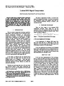
Fig. 1. Visual representation of a depth view showing (left) intensity and (right) depth map.
briefs this forward warping procedure and also the related algorithm that ensures correct visibility processing without involving 3-D polygonal rendering. A. Three-dimensional Image Warping Three-dimensional image warping is an IBR technique that involves extrapolating one reference depth view (the reference image and the associated depth map) in order to create a new image as seen from a nearby viewpoint. A representation of a complete depth view is shown in Fig. 1. The pixel intensity information is shown in Fig. 1(a). A visual approximation of the depth data is shown in the grey-scale image in Fig. 1(b). The white pixels represent those closest to the viewpoint. An extension of the depth view is the layered depth image (LDI) [16]–[18]. The LDI model contains depth and intensity information for all possible pixels along the line of sight. Occlusion errors evident when a simple depth view is warped are addressed where an LDI is employed instead. Using depth views or LDIs instead of a polygonal model can really only be justified if the 3-D scene is complex containing many polygons and/or textures. B. Image Reconstruction A digital image comprises pixels that are positioned on an integer lattice, a sampling grid. However when these discrete samples are warped to a new image plane, or grid, the values are very unlikely to exactly map to an integer position (a grid pixel). Inaccuracies are introduced that result in holes in the new image. The reference image is defined only at sampled locations and therefore needs to be reconstructed into a continuous signal. This is called image reconstruction. Reconstruction is an interpolation procedure applied to sampled data. Now this continuous signal can be sampled onto the regularly spaced output grid. Image reconstruction followed by sampling is called image resampling. The problem with this process is that data may be lost if the interpolation (reconstruction) stage cannot accurately recreate the continuous signal. This results in an undersampled signal and subsequent reconstruction results in aliasing. In order to avoid
Fig. 2. Magnified view on the right shows holes in undersampled foreground objects.
aliasing effects during resampling, the source image must first be filtered. Image reconstruction is a well researched area and the reader is referred to Wolberg’s bible for a comprehensive overview [19]. The most basic form of image reconstruction is to simply map one reference image pixel to a pixel position on the desired image plane. However this will often result in artifacts in the derived image due to undersampling. Fig. 2 shows the kind of artifacts that may arise. Pixels from background objects show through pinholes in foreground objects. Splatting is a simple technique to cope with these artifacts. The name splat is derived from the analogy of throwing a snowball against a wall. Instead of a one-to-one mapping between pixels of the reference image and derived image, splatting involves a one-to-many mapping. A noninteger splat is implemented by filling all derived image pixels whose centers lie pixel axis-aligned rectangle around the centre within a of the reference image pixel after warping, where is the splat size. It is agreed that the fixed size splat, and specifically of size 1.1 pixels, is an appropriate choice for a software based image warping system because of its simplicity and speed [1]. There are however drawbacks with the fixed size splat. If many reference pixels map to one derived pixel then the splat size must be large, perhaps two times two or greater. This results in a derived image that looks blocky. Variations include calculating splat size as dependent on the direction of the normal vector of the reference image pixel. This approach works better than
BAO et al.: DEEP COMPRESSION OF REMOTELY RENDERED VIEWS
447
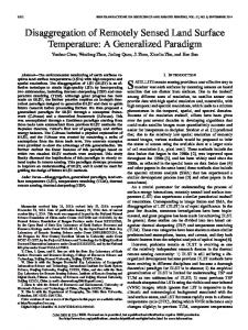
Fig. 3. The 3-D warper creates three consecutive intermediate frames while waiting for the residual image from the server to compensate the view (3,0,0).
the fixed-size splat for planar surfaces. However variable sized splats involve more calculation. A detailed description for various splatting methods is given in [5]. C. Remote Rendered Environment Based on Warping and View Compensations Fig. 3 shows the basic framework of the remote rendered environment. It is similar to the one described by Mann and Cohen-Or [13]. As an illustration of the framework we consider a mobile client connecting to a remote server and requesting to view a 3-D model. The server transmits an initial depth view image comprising color and pixel depth map, referred as an I-frame as in MPEG. The client then requests to view the model from a position relatively close to the current viewpoint. The desired viewing coordinates and the reference viewing coordinates are sent to the server. The client uses 3-D image warping to predict intermediate frames, or P-frames. These frames are reconstructed using fixed size splatting and Mark’s hole-filling algorithm. When the server receives the viewing parameters from the client it executes identical image warping and reconstruction. It also renders the 3-D model to obtain a rendered image. From the warped and rendered images the server calculates a view compensation (residual image), which tends to be sparse and correlated in context facilitating an efficient context modeling based compression. The server also compresses and transmits the depth map to the client. The client then compensates client’s warped frame and incorporates the corresponding depth map into the depth buffer using the compensated depth view (view compensation and depth map). The client now has a new reference frame for warp new P-frames. This environment can significantly increase the perceived frame rate when compared to a system that uses image streaming system alone. For example assume the client sends a request to the server to view the scene from a position three units to the right. The client’s 3-D image warper can create three consecutive predicted frames by repeatedly warping the reference image. By the time the third predicted frame has been created, the residual image has been received from the server and the I-frame can be displayed (see Fig. 3). If a viewpoint change is too significant (in viewing position or orientation or both) then clearly the warping algorithm will fail. There would not be enough information to warp a new view. In this case an entire depth view would be requested and transmitted from the server in a networked environment.
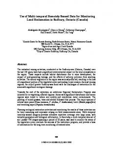
IV. CONTEXT MODELING AND COMPRESSION FOR DEPTH VIEW View compensations between the rendered view and the warped frame usually occur as a few isolated holes, often called artifacts, in the warped image due to under-sampling and occlusion, illustrated as the black areas in Fig. 4. Mark’s Ph.D. dissertation provides an excellent overview of this subject [1]. Due to the presence of the strong context correlation in the depth view, a context modeling based predictive coding [23], [24] is proposed to efficiently compress the depth view. Furthermore, since the client knows the exact coordinates of the holes in the warped image, the predicted hole residual can be packed to remove the redundant coordinate information thus further improve the compression. This motivates that a context based predictive and residual coding scheme be applied for the depth view.
A. Context Modeling and Residue Packing for Depth View The hole residual image or depth map in a depth view can be represented as a 2-D array of integers, respectively. In predictive coding, the encoder makes a prediction of the and then encodes the prediction residue next pixel value
The residue values in the nonhole areas would be mostly zero since their context are most all zero and thus the residue in the holes can be packed to give a compact residue . sequence as follows. The decoder can approximate • Recover the coordinated residue values from , , and the warped view. the quantization of sequence . • Calculate Since
the distortion of the partially compressed image is equivalent to the distortion of residue quantization. Therefore, to bound by the magnitude of a single error in compressed image
448
IEEE TRANSACTIONS ON MULTIMEDIA, VOL. 8, NO. 3, JUNE 2006
Fig. 4. Warped images for (a) original bitmap (225 Kb), (b) JPEG at compression ratio 20:1 (11.1 Kb), (c) JPEG at compression ratio 30:1 (7.2 Kb), and (d) context modeling at compression ratio of 55:1 (4.1 Kb).
Fig. 5. Context pattern for inner pixel P .
an integer , we simply aim at . A uniform residue quantizer, defined by, can achieve this bound
To accurately make a prediction of the next pixel value , we would like to design a context where pixel values
approxwould have a distribution whose mean imates well. For the reference image, we first classify the pixels into three categories and then define a pixel-adaptive context for each of the categories. For the depth map, we simply define the raster-scan context shown in Fig. 6 as the universal context for all the pixels. In the reference image, the boundaries of objects are usually depicted by the edges in the corresponding depth map and thus are readily available through edge detections in the depth map. The object boundaries in the reference image can help design a context adaptive to the classifications of pixels for a more accurate prediction. A pixel in the reference image is classified as a boundary pixel if it is on the boundary of an object, or classified as an inner pixel, if it is inside an object. Otherwise, the pixel is classified as a background pixel assuming that the pixels on the boundaries are four-connected, i.e. they are neighbored vertically or horizontally but not diagonally.
BAO et al.: DEEP COMPRESSION OF REMOTELY RENDERED VIEWS
449
Fig. 6. Context patterns for boundary pixel P .
Fig. 7. (a) Reference image, (b) rendered image, and (c) warped image with 1.1 splat. (d) View , (e) context modeling at compression ratio 65.4, and (f) compensated view.
For an inner pixel , its raster-scan context contains either boundary pixel or inner pixel (Fig. 5) and thus they are on the . In this case, the entire context surface of the same object as can serve as the prediction context for . For a boundary pixel , the possible patterns in the stand for the raster-scan context are shown in Fig. 6, where background pixel. is designed as the collection of The prediction context the black pixels in the raster-scan context. For a background , prediction context is designed as the collection of pixel all the background pixels in the raster-scan context. Since most pixels are inner pixels, the raster-scan context will serve as the
prediction context which fully utilizes the a priori information for the context modeling. B. WFA Representation of Quantized Residue Image can be encoded The quantized packed residue sequence using a lossy/lossless entropy coding scheme. Note that the , viewed as an image, is highly structured with sequence fractals, a WFA representation of the image would generally have small number of states and sparse transition matrices, which suggests that the WFA coding of the quantized residual image would yield a high compression ratio [23]. We briefly
450
IEEE TRANSACTIONS ON MULTIMEDIA, VOL. 8, NO. 3, JUNE 2006
Fig. 8. Warping images (zooming) and the view compensation.
Fig. 9. (a) Reference image, (b) warped image, (c) difference image, (d) quantized difference image with threshold = 20, (e) hole residual image, and (f) hole image with splat-size of 1.4.
describe the weighted finite automata coding of image as follows. For a detailed description of WFA coding, please refer to [23]. A multiresolution image is a collection of compatible resolution images, . Each pixel at resolution is assigned a word of length over the alphabet . We define as the address of the root of the quadtree
representing an image. Thus, each letter of is the address of of the length is a child of the root and every word in then an address of a unique node of the quadtree at the depth . Therefore in this formalism, a multiresolution image is a real function on . An -state WFA over alphabet is defined by a row vector , a column vector and weight matrices
BAO et al.: DEEP COMPRESSION OF REMOTELY RENDERED VIEWS
451
TABLE I
COMPRESSION RESULTS (KB) FOR A 320
tion
over
for all by
2 240, 24-bit COLOR IMAGE FOR VIEWPOINT ZOOMING
. It defines a multiresolution func-
At the extreme case lossless.
, the encoding will become
V. VIEW COMPRESSION OF PRIMITIVE RENDERING
for each and We may apply the WFA inference algorithm described in [24] of to minimize on the quantized residue
where is the approximation image computed by the WFA A, recursively until
where is a user-specified integer for bounding the WFA encoding error magnitude. Since an average-preserving WFA obtained by assigning a different state at level and higher will perfectly define the original finite resolution image, any integer , the WFA bound is achievable. At the extreme case encoding will become lossless. Decoding is the reverse of the process: the decoding of the WFA and then the reverse of the adaptive context modeling. Combining the WFA recursive encoding with the adaptive context modeling discussed in Section V-A, we obtain an efficient compression scheme for the depth view. Denoting by the WFA-coded residue image of and note that the distortion on the context modeling is , we have
We performed experiment on three classes of viewing movements, namely translation, rotation and zooming, dubbed primitive rendering operations, with various distances, angles and scaling factors, respectively and averaged the view compression of the primitive rendering to serve as the benchmark performance for other 3-D residual compression environment and the purely 3-D geometry rendering environment. Firstly, we experiment zooming on a 3-D model of a human face. The model, shown in Fig. 7, contains 3186 polygons and 1683 points. The size of the polygonal model is only 77 K with the texture of 900 K. The viewpoint is zoomed in toward the , illustrated face with the scaling factor in Fig. 8. This is a common viewpoint movement in interactive 3-D applications. The reference viewpoint is shown in Fig. 7(a) and the exact, zoomed image is shown in Fig. 7(b). The screen resolution 320 240 pixels. We experimented with a variety of noninteger splat sizes and the resultant graph is shown in Fig. 9. The file sizes have been compressed using the context modeling. Fig. 7(c) shows the warped image for a splat of size 1.1 pixels. Fig. 7(d) shows the resulting quantized difference image for a threshold value of five. Fig. 7(e) shows the hole residual image, formed simply by searching for holes in the derived image. For comparison, Fig. 7(f) is a screenshot showing the warped image for a splat size of 1.4 pixels. As can be seen all holes have been eliminated although a slight “blocky” effect is evident. However for a small screen size where detail is less noticeable we believe a fixed size splat of 1.4 pixels produces acceptable results. Importantly the size of hole residual image is decreased significantly. Table I shows the compression results for each of zooming operations as well as the average for the splat of size 1.4. Using a 1.4 splat we experimented compression results for both a translational (north, south, west, and east translations) and projective (rotation only) warp of a textured room scene. This model, shown in Fig. 10(a), contains three textures, the wall on the left, the floor and the bridge visible through the window.
452
IEEE TRANSACTIONS ON MULTIMEDIA, VOL. 8, NO. 3, JUNE 2006
TABLE II
COMPRESSION RESULTS (KB) FOR A 320
2 240, 24-bit COLOR IMAGE FOR VIEWPOINT TRANSLATIONS
TABLE III
COMPRESSION RESULTS (KB) FOR A 320
2 240, 24-bit COLOR IMAGE FOR VIEWPOINT ROTATIONS
Fig. 10. Splat size versus compressed image size for the average view movement for 320 240, 24-bit color image.
2
The total size of the textures is 3.35 MB, the number of vertices 9298 and the number of polygons is 17 980. The scene therefore is not particularly complex but the presence of textures increases the rendering load considerably. There are 26 separate 3-D objects that comprise the scene. The room scene is lit with ambient light and one spotlight. The spotlight adds view-dependent specular lighting. This means that pixel intensity changes
when the viewpoint is transformed. For small changes in viewpoint the intensity difference is very subtle and in fact is often unnoticeable. Table II and Fig. 9 show results of the translational warp experiment with the relative viewpoint translation 1, 3, 5, 7, 9, etc. where in our experiment, represented by the relative translation unit is 10 pixels on a 320 240 view screen. For comparison purposes an uncompressed bitmap has a file size of 126.5 K and a five-frame MPEG movie has file size of 60.7 K. The MPEG movie shows noticeable degradation in quality as a result of the compression. A JPEG2000 file with a high quality factor has a file size of approximately 30 K. This gives an indication of file sizes for a strictly image streaming system. Table III give similar results for a projective warp with 2, 4, 6, 8, 10 radius degrees. relative rotation angle We adopt a splat size of 1.4 pixels in the primitive rendering for benchmark as it achieves optimal tradeoff between the compression ratio and the visual quality. This splat size eliminated most pinholes for moderate viewpoint transformations with limited impact on image quality. Fig. 10 shows the compression ratios verse different splat sizes for the average primitive rendering. The major download is clearly the initial reference image and the corresponding depth map with an average size of 65 K for the
BAO et al.: DEEP COMPRESSION OF REMOTELY RENDERED VIEWS
453
TABLE IV INTEGRATED FRAME RATES FOR 24-Bit COLOR DISPLAY ASSUMING v = 5 (NOTE THE NUMBERS ARE IN KBITS), IN COMPARISON WITH THE STORAGE AND BANDWIDTH REQUIREMENT AT THE SAME FRAME RATE FOR 3-D RENDERING
320 240 resolution. However subsequent view compensations will be very small in size at the range of 5 K every 5–10 frames for an average viewing rendering. Also note that the compressed file sizes are likely to be significantly less than those in the tables since low-end mobile devices are likely to be equipped with 16-bit RGB color instead of 24-bit color and the view compensations with reduced color resolution would be better compressed. VI. EXPERIMENT ON COMPRESSION A. Depth View Compression In this section, we apply the context modeling compression for the view compensations, which are periodically requested by the client, to give an integrated performance of the rendering frame rates, view transmission and storage in a remote rendering environment. We apply the scheme for the reference image and the depth map, separately, since they possess largely different prediction context models. This would not affect the efficiency of the 3-D warping since the intensity and depth information are referred separately during the process. The compression could be jointly designed for depth views if depth views are represented as a joint data structure similar to the representation of LDIs. We apply the lossy JPEG 2000 on depth view sequence, aimed at presenting a benchmarked evaluation with the context modeling scheme. A sophisticated lossless compression scheme, Wu’s CALIC [26], are applied on the references and the depth view sequence aimed at yielding a better compression ratio for comparison with the context modeling scheme. The reference image shown in Fig. 1(a) is compressed using several JPEG2000 compression ratios and the depth map was compressed losslessly using Lempel-Ziv-Welch [25] algorithm since JPEG2000, as a statistics based transform coder, would usually yield poor compression for the synthetic images such as depth maps. Then a 3-D image warp is applied for a lateral viewpoint translation to the right. (Fig. 12). Note that each image comprises 320 240 pixels and with 24-bit RGB color. Fig. 4(a) shows the results of warping (rotation) the original bitmap. In the experiment, the integrated frame rates (warping-rates and transmission and decompression of the view compensations) and storage requirement were measured on a remote environment configured as follows. The client is a mobile device with a 400 MHz processor, a 320 240 pixel display and 16-bit color, connected to Internet through a wireless LAN, where the average bandwidth is 250 Kbps and the round-trip latency is 50
Fig. 11. Compressed file size versus depth map resolution for rotations in Fig. 12.
ms, approximating a typical 2.5 G mobile network. The server is an SGI Octane-2 Dual MIPS workstation with V6 Graphics, capable of instant 3-D graphics rendering, and supports HTTP/1.2 protocol with the persistent connections, enabling and ensuring the transmission of multiple requests and responses (residuals), which leads to assumption that the rendering and warping rates on the server are superior to the warping rates on clients. The remote environment is capable of increasing the perceived frame rate when compared to a system that uses image streaming to mobile clients alone. In the environment, given the bandwidth and the roundtrip latency , the achievable integrated frame rate is a function of the size of the compressed depth image , the client processing time , the client warping rate and the expected view compensation rate (the number of view compensations over the total number of frames) derivable as follows. On the client, the total warping and processing time and the total transmission time is . Thus (1) Thus to achieve an increased frame rate, either the client is expected to warp more frames and/or the network bandwidth should be increased proportionally as in (1) (a decrease of the depth image size and the client processing time would also be of help). The client is expected to send the requests in advance to synchronize the client rendering and the server response. In our experimental environand is 3–4 frames. Assuming ment, , in order to achieve a frame rate, the client is exframes pected to warp at least
454
IEEE TRANSACTIONS ON MULTIMEDIA, VOL. 8, NO. 3, JUNE 2006
Fig. 12. Lateral viewpoint warp for 9 bit resolution depth (left) and 8 bit resolution (right).
Fig. 13. PSNR for compressed reference image for zooming in Fig. 7.
per second. Table IV gives the warping rates, the corresponding compressed views and bandwidth requirement, and the integrated frame rates achievable in comparison with the JPEG2000 based remote environment and the purely remote 3-D rendering environment (i.e. without client warping). It is observed that the compressions ratios achieved by the context modeling scheme almost doubles those by JPEG2000. Note that the compression ratios for the natural scene (ART GALLERY) are much higher than those for the synthetic scene (SHAPES) in Fig. 15. For both scenes, the compressed depth views are at 37–58 Kb, at which a REALTIME transmission over the Internet is expected. Fig. 7 shows another example of warping (zooming) the original bitmap. Fig. 7(a) and (b) are original reference and rendered view; Fig. 7(c) and (d) give the warped image and its view compensation. Fig. 7(e) shows the view compensation compressed at 65.4:1 using the context modeling; Fig. 7(f) gives the warped view compensated by the view in (e). Figs. 13 and 14 shows the peak signal to noise ratio (PSNR) of warping the reference image compressed by the context modeling as compared to warping the JPEG2000 compressed reference image. We also tried both the JPEG 2000 and context modeling on a more synthetic scene. Fig. 11(a) is a screenshot of a 3-D scene,
Fig. 14. PSNR for compressed reference image for rotation in Fig. 10.
Shapes, comprising a collection of complex, shaded 3-D shapes. The average compression ratio for this example is at 16:1 for JPEG2000 and 36:1 for the context modeling. Fig. 4(b) and (4c) show the visual results of warping a reference image that has been compressed at 20:1 and 30:1 using JPEG 2000 respectively and Fig. 4(d) show the result of warping the reference image compressed at 55:1 using the context modeling. It is observed that JPEG2000 compression at a ratio greater than 40:1 would produce an unacceptably poor quality image but the context modeling will still yield a perceptually acceptable warped image even at a ratio up to 60:1. A compression ratio at 20:1 using the context modeling resulted in a visually lossless image. B. Reduction of Depth View Resolution We also examined the effect of reducing the resolution of the depth data from a starting resolution at 16 bpp. The visual effect of warping the depth map for 9 bits and 8 bits of depth resolution, compressed using the context modeling is shown in Fig. 12(a) and (b). The images are almost identical. However in Fig. 12(b) there is no black pixels shown behind the second more distant pedestal. This is the effect of less depth precision.
BAO et al.: DEEP COMPRESSION OF REMOTELY RENDERED VIEWS
455
Fig. 15. (a) Reference image, (b) depth map, (c) warp for 8-bit depth resolution, (d) warp for 9-bit depth resolution, (e) warp for 10-bit depth resolution, and (f) warp for 16-bit depth resolution.
Fig. 11 shows that the compressed file sizes for 8-, 9-, and 10-bit depth maps using lossless JPEG2000 and the lossy/loss-
less context modeling, respectively. Note that the context modeling can achieve a compression ratio 20–25% better that
456
IEEE TRANSACTIONS ON MULTIMEDIA, VOL. 8, NO. 3, JUNE 2006
the lossless JPEG2000 for the various depth maps. Fig. 15(c) shows a warped image for 8 bits of depth resolution for the Shapes 3-D scene. The viewpoint transformation consists of a forward movement followed by a small anti-clockwise rotation around the y-axis. Fig. 15(d) and (e) show the improvements obtained using 9-and 10-bit depth maps. The difference between an image warped from a 10-bit map and a 16-bit depth map is negligible as shown in Fig. 15(f). VII. CONCLUSION The paper presents an efficient remote rendering environment based on 3-D image warping and a deep compression of view compensations using a pixel-adaptive context modeling. The context modeling based view compression offers a significantly high compression ratio with almost no loss in perceptual quality between the rendered image and the warped images where the pixel-adaptive context is readily available from the depth map. The proposed scheme can achieve a ratio up to 100:1 for the view compensation images compared to a ratio at 50:1 by JPEG2000 at a similar PSNR level thus enabling efficient remote rendering of complex 3-D scene over a network at an average bandwidth as low as 110 Kbps. We also experimented the 3-D warping using the resolution reduced depth map knowing that the resolution reduction would only indirectly affect the warping of the reference image. The experiment shows that a resolution of only 10 bits provides an almost imperceptible loss of warped image quality for the benchmark scenes. REFERENCES [1] W. Mark, “Post rendering 3D image warping: Visibility, reconstruction and performance for depth image warping,” Ph.D. dissertation, Univ. North Carolina, Chapel Hill, 1999. [2] R. Krishnamurthy, B.-B. Chai, H. Tao, and S. Sethuraman, “Compression and transmission of depth maps for image-based rendering,” in Proc. IEEE Int. Conf. Image Processing (ICIP’01), 2001, vol. 3, pp. 828–831. [3] Y. Bayakovski, L. Levkovich-Maslyuk, A. Ignatenko, A. Konushin, D. Timasov, A. Zhirkov, M. Han, and I. K. Park, “Depth image-based representations for static and animated 3D objects,” in Proc. ICIP’02, 2002, vol. 3, pp. 25–28. [4] M. Zwicker, M. Gross, and H. Pfister, A Survey and Classification of Real Time Rendering Methods, Mitsubishi Electric Research Laboratories Tech. Rep. 2000-09, Mar. 29, 2000. [5] P. Bao and D. Gourley, “Real-time Rendering of 3-D scenes using subband 3-D warping,” IEEE Trans. Multimedia, vol. 6, no. 6, pp. 786–790, Dec. 2004. [6] M. Levoy et al., “The digital michelangelo project: 3D scanning of large statues,” in SIGGRAPH 2000, 2000, pp. 131–144. [7] M. Magnor and B. Girod, “Data compression for light-field rendering,” IEEE Trans. Circuits Syst. Video Technol., vol. 10, no. 3, pp. 338–343, Apr. 2000. [8] D. Cohen-Or, Y. Mann, and S. Fleishman, “Deep compression for streaming texture intensive animations,” in SIGGRAPH ’99, 1999, pp. 261–267. [9] D. Koller, M. Turitzin, M. Levoy, M. Tarini, G. Croccia, P. Cignoni, and R. Scopigno, “Capture from images: protected interactive 3D graphics via remote rendering,” ACM Trans. Graph., vol. 23, no. 3, pp. 695–703, Aug. 2004. [10] M. Levoy, “Polygon-assisted JPEG and MPEG compression of synthetic images,” in Proc. SIGGRAPH’95, 1995, pp. 21–28. [11] D. Cohen-Or, “Model-based view-extrapolation for interactive VR web systems,” in Proc. Computer Graphics Int.’97, Kinepolis, Belgium, Jun. 23–27, 1997, pp. 104–112. [12] L. McMillan, “An image-based approach to three-dimensional computer graphics,” Ph.D. dissertation, Univ. North Carolina, Chapel Hill, 1997.
[13] Y. Mann and D. Cohen-Or, “Selective pixel transmission for navigating in remote virtual environments,” Comput. Graph. Forums, vol. 16, no. 3, pp. 201–206, Sep. 1997. [14] I. Yoon and U. Neumann, “Compression of computer graphics images with image-based rendering,” in Proc. IEEE SPIE ’99 Multimedia Computing and Networking, San Jose, CA, Jan. 24–29, 1999, pp. 66–75. [15] T. Hudson and B. Mark, Multiple Image Warping for Remote Display of Rendered Images Univ. North Carolina, Chapel Hill, Comput. Sci. Tech. Rep. TR99-024, 1999. [16] L. Shade, S. Gortler, L. He, and R. Szeliski, “Layered depth images,” in Proc. SIGGRAPH’98, 1998, pp. 231–242. [17] J. Duan and J. Li, “Compression of layered depth image,” in IEEE Data Compression Conference, Snowbird, UT, Mar. 2001, pp. 331–340. [18] V. Popescu, A. Lastra, D. G. Aliaga, and M. O. Neto, “Efficient warping for architectural walkthroughs using layered depth images,” Proc. IEEE Visualization, pp. 211–215, 1998. [19] G. Wolberg, Digital Image Warping. Los Alamitos, CA: IEEE Comput. Soc. Press, 1990. [20] V. Popescu, “Forward rasterization: A reconstruction algorithm for image-based rendering,” Ph.D. dissertation, Univ. North Carolina, Chapel Hill, Jan. 17, 2001. [21] J. Shade, S. Gortler, L.-W. He, and R. Szeliski, “Layered depth images,” in Proc. SIGGRAPH ’98, 1998, pp. 231–242. [22] W. R. Mark and G. Bishop, Efficient Reconstruction Techniques for Post-Rendering 3D Image Warping Univ. North Carolina, Chapel Hill, Comput. Sci. Tech. Rep. TR98-011, Mar. 21, 1998. [23] X. Wu and P. Bao, “L -constrained high-fidelity image compression via adaptive context modeling,” IEEE Trans. Image Process., vol. 9, no. 4, pp. 536–542, Apr. 2000. [24] P. Bao and X. Wu, “Near-lossless L -constrained image compression using weighted finite automata encoding,” Comput. Graph., vol. 22, no. 2–3, pp. 217–223, Jun. 1998, T.A.. [25] Welch, “A technique for high performance data compression,” IEEE Computer, vol. 17, no. 6, pp. 8–19, Jun. 1984. [26] X. Wu and N. Memon, “Context-based, adaptive, lossless image codec,” IEEE Trans. Commun., vol. 45, no. 4, pp. 437–444, Apr. 1997. Paul Bao (SM’02) received the Ph.D. degree from the University of Calgary, Calgary, AB, Canada in 1988. He served on the faculty of Computer Science Department, University of Calgary, from 1988 to 1990, and then proceeded to work at IBM Canada as a Staff Analyst. He was an Associate Professor in the Computing Department at The Hong Kong Polytechnic University, the Department of Information Engineering at The Chinese University of Hong Kong, and at School of Computer Engineering, Nanyang Technological University, during 1995–2005. He is currently a Professor in Department of Information Technology, University of South Florida, Tampa. His research interests are in computer graphics and image processing, image-based rendering, distributed graphics and rendering, image/video coding, etc. He has published over 130 research papers in those areas. Douglas Gourlay graduated from the University of Strathclyde, U.K., in 1989 Since his graduation, he has performed research work in the areas of interactive 3-D environment and applications at Yarrow Shipbuilders, Glasgow, U.K., Strathclyde University, U.K., the National University of Singapore, the Hong Kong Polytechnic University, and the Chinese University of Hong Kong. He has published over 12 papers in these areas. Youfu Li (SM’01) received the B.Sc. and M.Sc. degrees in electrical engineering from Harbin Institute of Technology (HIT), China, in 1982 and 1986, respectively. He receievd the Ph.D. degree in robotics from the Department of Engineering Science, Oxford University, U.K., in 1993. From 1993 to 1995, he was a post-doctoral researcher in the Department of Computer Science, University of Wales, Aberystwyth, U.K. He joined the City University of Hong Kong in 1995. His research interests include robot vision, robot sensing and sensor based control, robotics, interface devices for VR. In these areas, he has published over 100 papers in refereed international journals and conferences. Dr. Li has served as program committee member of different international conferences.