Siemens Automotive and Detroit Diesel Corporation. ..... requirements patterns can be used in an untimed model of an automotive embedded ...... Technician.
DEFINING AND USING REQUIREMENTS PATTERNS FOR EMBEDDED SYSTEMS By SASCHA J. KONRAD
AN ABSTRACT OF A THESIS Submitted to Michigan State University in partial fulfillment of the requirements for the degree of MASTER OF SCIENCE Department of Computer Science 2003 Advisor: Dr. Betty H.C. Cheng
ABSTRACT DEFINING AND USING REQUIREMENTS PATTERNS FOR EMBEDDED SYSTEMS By SASCHA J. KONRAD
It is well-known that requirements modeling and analysis is one of the most difficult tasks in the software development process, but this problem is greatly exacerbated for embedded systems given the hardware constraints and the potentially complex control logic. This research investigates how an approach similar to design patterns by the Gang of Four can be applied to requirements specifications, termed requirements patterns. Specifically, our research explores how object-oriented modeling notations, such as the Unified Modeling Language (UML), can be used to represent structural and behavioral information as part of commonly occurring requirements patterns. In order to maximize reuse, we focus on requirements patterns for embedded systems. This work also investigates how the UML diagrams, based on the requirements patterns, can be automatically analyzed, using the SPIN model checker, for adherence to constraints specified in LTL (linear time temporal logic) using a previously developed formalization framework by McUmber et al.. In addition, we extended the formalization framework to support rigorous analysis of UML models containing timing information. Subsequently, we can analyze embedded systems requirements involving timing constraints specified in MTL (metric temporal logic). We also describe the application of the requirements patterns and formal analysis of timed and untimed properties to three embedded systems from the automotive industry.
DEFINING AND USING REQUIREMENTS PATTERNS FOR EMBEDDED SYSTEMS By SASCHA J. KONRAD
A THESIS Submitted to Michigan State University in partial fulfillment of the requirements for the degree of MASTER OF SCIENCE Department of Computer Science 2003
ABSTRACT DEFINING AND USING REQUIREMENTS PATTERNS FOR EMBEDDED SYSTEMS By SASCHA J. KONRAD
It is well-known that requirements modeling and analysis is one of the most difficult tasks in the software development process, but this problem is greatly exacerbated for embedded systems given the hardware constraints and the potentially complex control logic. This research investigates how an approach similar to design patterns by the Gang of Four can be applied to requirements specifications, termed requirements patterns. Specifically, our research explores how object-oriented modeling notations, such as the Unified Modeling Language (UML), can be used to represent structural and behavioral information as part of commonly occurring requirements patterns. In order to maximize reuse, we focus on requirements patterns for embedded systems. This work also investigates how the UML diagrams, based on the requirements patterns, can be automatically analyzed, using the SPIN model checker, for adherence to constraints specified in LTL (linear time temporal logic) using a previously developed formalization framework by McUmber et al.. In addition, we extended the formalization framework to support rigorous analysis of UML models containing timing information. Subsequently, we can analyze embedded systems requirements involving timing constraints specified in MTL (metric temporal logic). We also describe the application of the requirements patterns and formal analysis of timed and untimed properties to three embedded systems from the automotive industry.
Copyright by SASCHA J. KONRAD 2003
To my family in Germany. Without their support and encouragement this thesis would not have occurred.
iv
Acknowledgements
I am grateful to all the students and faculty of the Software Engineering and Networking Systems (SENS) Laboratory at Michigan State University. I especially wish to thank my advisor Dr. Betty Cheng for her advice, patience, support, and excellent editing skills that made writing this thesis possible. Furthermore, I wish to thank Laura Anne Campbell for spending numerous hours with me working on papers and Min Deng for assisting me with extending and altering the formalization framework originally developed by Dr. Bill McUmber, which is used extensively in this work. I greatly appreciate the opportunity provided by the International Student Exchange program between Michigan State University and University of Kaiserslautern that enabled me to initiate my graduate studies at Michigan State University, which has since evolved into the completion of my MS thesis from MSU. Additionally, I would like to thank Dr. Gerard Holzmann and Dr. Dragan Bosnacki for their helpful comments on the timing extensions applied to the formalization framework using the Spin model checker. This work has been supported in part by NSF grants EIA-0000433, EIA-0130724, CDA-9700732, CCR-9901017, Department of the Navy, Office of Naval Research under Grant No. N00014-01-1-0744, Eaton Corporation, and in cooperation with Siemens Automotive and Detroit Diesel Corporation.
v
Table of Contents LIST OF TABLES
ix
LIST OF FIGURES
x
1 Introduction
1
2 Background 2.1 Design Patterns . . . . . . . . . . . . . . . . . . . . . 2.1.1 Pattern Basics . . . . . . . . . . . . . . . . . . 2.1.2 Capturing and Classifying Design Patterns . . 2.1.3 Design Pattern Application . . . . . . . . . . 2.2 Unified Modeling Language (UML) . . . . . . . . . . 2.3 Formal Specifications and Specification Patterns . . . 2.4 Formal Specification Languages and Model Checking 2.4.1 Linear Time Temporal Logic (LTL) . . . . . . 2.4.2 Metric Temporal Logic (MTL) . . . . . . . . . 2.4.3 Spin and Promela . . . . . . . . . . . . . . . . 2.5 Definition of Terms . . . . . . . . . . . . . . . . . . .
. . . . . . . . . . .
3 Describing Requirements Patterns 3.1 Requirements Pattern Template . . . . . . . . . . . . . 3.2 Requirements Patterns Catalogue Overview . . . . . . 3.3 Classifying Requirements Patterns . . . . . . . . . . . . 3.4 Requirements Pattern Repository . . . . . . . . . . . . 3.4.1 Controller Decompose (29): Structural Pattern . 3.4.2 Actuator-Sensor (38): Structural Pattern . . . . 3.4.3 Watchdog (48): Behavioral Pattern . . . . . . . 3.4.4 Examiner (56): Behavioral Pattern . . . . . . . 3.4.5 Fault Handler (63): Behavioral Pattern . . . . . 3.4.6 Mask (73): Structural Pattern . . . . . . . . . . 3.4.7 Moderator (78): Structural Pattern . . . . . . . 3.4.8 User Interface (82): Strcutural Pattern . . . . . 3.4.9 Communication (91): Behavioral Pattern . . . . 3.4.10 Actuation-Monitor (98): Structural Pattern . .
. . . . . . . . . . . . . . . . . . . . . . . . .
4 Requirements Patterns-Based Modeling and Analysis 4.1 Formalized UML . . . . . . . . . . . . . . . . . . . . . . 4.2 General Modeling and Analysis Process . . . . . . . . . . 4.3 Model Checking an Untimed Anti-lock Brake System . . 4.3.1 Simulation and Model Checking . . . . . . . . . . 4.3.2 Process for Using Requirements Patterns . . . . . 4.3.3 Construction of UML Models . . . . . . . . . . . 4.3.4 FaultHandler Requirements Pattern Specifications 4.3.5 System Abstraction . . . . . . . . . . . . . . . . . vi
. . . . . . . . . . . . . . . . . . . . . . . . . . . . . . . . .
. . . . . . . . . . . . . . . . . . . . . . . . . . . . . . . . .
. . . . . . . . . . . . . . . . . . . . . . . . . . . . . . . . .
. . . . . . . . . . . . . . . . . . . . . . . . . . . . . . . . .
. . . . . . . . . . . . . . . . . . . . . . . . . . . . . . . . .
. . . . . . . . . . . . . . . . . . . . . . . . . . . . . . . . .
. . . . . . . . . . .
5 6 6 6 8 9 14 15 15 15 16 17
. . . . . . . . . . . . . .
21 21 24 25 29 29 38 48 56 63 73 78 82 91 98
. . . . . . . .
104 104 105 107 107 108 109 110 112
4.3.6 4.3.7
Scenario Definition . . . . . . . . . . . . . . . . . . . . . . . . 115 Verification Results . . . . . . . . . . . . . . . . . . . . . . . . 116
5 Model Checking with Timing 5.1 Background on Timing . . . . . . . . . . . . . . . . . . . . . . . . . . 5.1.1 B¨ uchi Automata and Timed Automata with Discrete Time Semantics . . . . . . . . . . . . . . . . . . . . . . . . . . . . . . 5.1.2 Digital-Clock Model . . . . . . . . . . . . . . . . . . . . . . . 5.1.3 How to Instantiate Timed Claims . . . . . . . . . . . . . . . . 5.2 Adding Timing Information to UML . . . . . . . . . . . . . . . . . . 5.2.1 Timing Syntax in UML Class and State Diagrams . . . . . . . 5.2.2 Timing Semantics for Embedded Systems . . . . . . . . . . . . 5.2.3 Approach Overview . . . . . . . . . . . . . . . . . . . . . . . . 5.3 Discrete Time Rules Extensions in Hydra . . . . . . . . . . . . . . . . 5.3.1 Original Promela Rule Modifications/Extensions . . . . . . . . 5.3.2 Additional Promela Rules . . . . . . . . . . . . . . . . . . . . 5.3.3 Validation of Formalization Rules . . . . . . . . . . . . . . . . 5.3.4 Related Work in Timed Model Checking with Spin . . . . . . 5.4 Model Checking a Timed Electronically Controlled Steering System . 5.4.1 Process . . . . . . . . . . . . . . . . . . . . . . . . . . . . . . 5.4.2 Application Overview . . . . . . . . . . . . . . . . . . . . . . . 5.4.3 Abstraction, Equivalence Classes, Timing Granularity, and Scenarios . . . . . . . . . . . . . . . . . . . . . . . . . . . . . . . 5.4.4 Modeling the Electronically Controlled Steering System . . . . 5.4.5 Analysis of Coarse-Grained View . . . . . . . . . . . . . . . . 5.4.6 Analysis of Fine-Grained View . . . . . . . . . . . . . . . . . .
121 121 122 123 124 126 126 127 128 129 130 132 133 138 139 139 141 142 145 146 148
6 Related Work 153 6.1 Analysis Patterns . . . . . . . . . . . . . . . . . . . . . . . . . . . . . 153 6.2 Problem Frames . . . . . . . . . . . . . . . . . . . . . . . . . . . . . . 155 6.3 Requirements Patterns Via Events/Use-Cases . . . . . . . . . . . . . 156 6.4 Goal-Driven Requirements Engineering . . . . . . . . . . . . . . . . . 156 6.4.1 KAOS . . . . . . . . . . . . . . . . . . . . . . . . . . . . . . . 157 6.4.2 From Non-Functional Requirements to Design through Patterns 158 6.5 Scenario-based Requirements Engineering . . . . . . . . . . . . . . . . 159 6.6 Architectural Patterns . . . . . . . . . . . . . . . . . . . . . . . . . . 160 6.7 Embedded System Design Patterns . . . . . . . . . . . . . . . . . . . 161 6.8 Real-Time Design Patterns . . . . . . . . . . . . . . . . . . . . . . . . 162 6.9 Formal Methods for Requirements Engineering . . . . . . . . . . . . . 162 6.9.1 SCR . . . . . . . . . . . . . . . . . . . . . . . . . . . . . . . . 163 6.9.2 RSML . . . . . . . . . . . . . . . . . . . . . . . . . . . . . . . 164 6.9.3 Reuse of a Formal Model for Requirements Validation . . . . . 164 7 Conclusions
166
vii
APPENDICES
169
A Additional Case Study A.1 Modeling the Diesel Filter System . . . . . . . . . . . . . . A.1.1 Application Overview . . . . . . . . . . . . . . . . . A.1.2 Requirements Patterns for the Diesel Filter System A.1.3 Abstraction and Equivalence Classes . . . . . . . . A.1.4 UML Modeling for the Diesel Filter System . . . . A.2 Analysis Using Requirements and Specification Patterns . A.2.1 Requirement 1 . . . . . . . . . . . . . . . . . . . . . A.2.2 Requirement 2 . . . . . . . . . . . . . . . . . . . . . A.2.3 Requirement 3 . . . . . . . . . . . . . . . . . . . . .
170 170 170 171 173 174 178 178 180 183
. . . . . . . . .
. . . . . . . . .
. . . . . . . . .
. . . . . . . . .
. . . . . . . . .
. . . . . . . . .
B Example Promela Specification
186
LIST OF REFERENCES
189
viii
List of Tables 3.1 3.2 3.3 3.4
Requirements pattern template . . . . . . . . . . . . . . . . . Current list of requirements patterns for embedded systems . . Pattern classification according to purpose . . . . . . . . . . . Pattern classification according to non-functional requirements
4.1 4.2
Results of the verification for the first property of the ABS . . . . . . 119 Results of the verification for the second property of the ABS . . . . 120
5.1
The definition of the homomorphic mapping of classes from the UML metamodel to the Promela metamodel. . . . . . . . . . . . . . . . . . Coarse- and fine-granularity views of the ECS system . . . . . . . . . Analysis results for the coarse-grained ECS system . . . . . . . . . . Analysis results for the fine-grained ECS system . . . . . . . . . . . .
5.2 5.3 5.4
ix
. . . .
. . . .
. . . .
. . . .
23 24 26 27
130 144 149 152
List of Figures 2.1 2.2 2.3 2.4 2.5
UML use-case diagram example . . . . . . . . . . UML class diagram example . . . . . . . . . . . . UML state diagram example . . . . . . . . . . . . UML sequence diagram example . . . . . . . . . . Our view on the structure of an embedded system
3.1 3.2 3.3 3.4 3.5 3.6 3.7 3.8 3.9 3.10 3.11 3.12 3.13 3.14 3.15 3.16 3.17 3.18 3.19 3.20 3.21 3.22 3.23 3.24 3.25 3.26 3.27 3.28 3.29 3.30 3.31 3.32 3.33
Requirements patterns relationships . . . . . . . . . . . . . . . . . . . UML use-case diagram of the Controller Decompose (29) Pattern . . UML package diagram of the Controller Decompose (29) Pattern . . . UML use-case diagram of the Actuator-Sensor (38) Pattern . . . . . Four-variable model [60] . . . . . . . . . . . . . . . . . . . . . . . . . UML class diagram of the Actuator-Sensor (38) Pattern . . . . . . . UML sequence diagram example of the Actuator-Sensor (38) Pattern UML use-case diagram of the Watchdog (48) Pattern . . . . . . . . . UML class diagram of the Watchdog (48) Pattern . . . . . . . . . . . UML state diagram of the Watchdog (48) Pattern (1) . . . . . . . . . UML state diagram of the Watchdog (48) Pattern (2) . . . . . . . . . UML sequence diagram example of the Watchdog (48) Pattern . . . . UML use-case diagram of the Examiner (56) Pattern . . . . . . . . . UML class diagram of the Examiner (56) Pattern . . . . . . . . . . . UML state diagram of the Examiner (56) Pattern (1) . . . . . . . . . UML state diagram of the Examiner (56) Pattern (2) . . . . . . . . . UML sequence diagram example of the Examiner (56) Pattern . . . . UML use-case diagram for the Fault Handler (63) Pattern . . . . . . Structural Diagram for the Fault Handler (63) Pattern . . . . . . . . UML state diagram of the ComputingComponent in the Fault Handler (63) Pattern . . . . . . . . . . . . . . . . . . . . . . . . . . . . . . . . UML class diagram of the Mask (73) Pattern . . . . . . . . . . . . . UML sequence diagram of the Mask (73) Pattern . . . . . . . . . . . UML class diagram of the Moderator (78) Pattern . . . . . . . . . . . UML sequence diagram of the Moderator (78) Pattern . . . . . . . . UML use-case diagram of the User Interface (82) Pattern . . . . . . . UML class diagram of the User Interface (82) Pattern . . . . . . . . UML sequence diagram example of the User Interface (82) Pattern . Structure of the Communication (91) Pattern . . . . . . . . . . . . . UML sequence diagram describing behavior in case of a bus failure [21] UML sequence diagram for multi-channel voting . . . . . . . . . . . . UML use-case diagram of the Actuation-Monitor (98) Pattern . . . . UML class diagram of the Actuation-Monitor (98) Pattern . . . . . . UML sequence diagram of the Actuation-Monitor (98) Pattern . . . .
4.1 4.2
Overview of our approach . . . . . . . . . . . . . . . . . . . . . . . . 106 Abstracted UML class diagram of the model . . . . . . . . . . . . . . 110
x
. . . . .
. . . . .
. . . . .
. . . . .
. . . . .
. . . . .
. . . . .
. . . . .
. . . . .
. . . . .
. . . . .
10 11 12 13 20 28 30 32 39 40 41 43 49 50 51 52 53 57 58 59 59 60 65 67 69 74 77 78 79 83 85 86 96 97 97 98 100 101
4.3 4.4 4.5 4.6 4.7
Abstracted UML state diagram for the FaultHandler . . . . . Abstracted UML state diagram for the ComputingComponent Equivalence classes for system conditions . . . . . . . . . . . UML state diagram of the environment class . . . . . . . . . Promela code of the non-deterministic scenario selection . .
5.1 5.2 5.3 5.4 5.5 5.6 5.7 5.8 5.9 5.10 5.11 5.12 5.13 5.14
Time invariant: Discrete time interpretation . . . . . . . . Example event sequence with respective time slices . . . . Example UML model with timing information . . . . . . . Timer definitions in the Timer struct . . . . . . . . . . . . Promela code of the Timer process . . . . . . . . . . . . . . Promela code of a transition with time invariant . . . . . . Altered process for an LTL response property . . . . . . . Composite state Composite1 from Figure 5.3(b) in Promela Model checking process . . . . . . . . . . . . . . . . . . . . Time-sensitive requirements of the ECS system . . . . . . Equivalence classes for system conditions . . . . . . . . . . ECS UML object diagram . . . . . . . . . . . . . . . . . . Faulty Ramp UML state diagram (Elided) . . . . . . . . . Faulty Watchdog UML state diagram (Elided) . . . . . . .
. . . . .
. . . . .
. . . . .
. . . . .
. . . . .
113 114 115 117 118
. . . . . . . . . . . . . . . . . . . . . code . . . . . . . . . . . . . . . . . .
. . . . . . . . . . . . . .
. . . . . . . . . . . . . .
. . . . . . . . . . . . . .
123 124 127 134 135 136 136 137 140 142 143 146 148 151
A.1 Requirements-pattern-guided UML class diagram of the Diesel Filter System . . . . . . . . . . . . . . . . . . . . . . . . . . . . . . . . . . . A.2 Equivalence classes for system conditions . . . . . . . . . . . . . . . . A.3 UML object diagram of the abstracted Diesel Filter System . . . . . . A.4 UML state diagram of the ComputingComponent (elided) . . . . . . . A.5 Animation trace of the ComputingComponent state diagram (Requirement 1) . . . . . . . . . . . . . . . . . . . . . . . . . . . . . . . . . . A.6 Elided UML sequence diagram (Requirement 2) . . . . . . . . . . . . A.7 Animation trace of UserInterface state diagram (Requirement 3) . . .
xi
172 174 176 177 180 182 185
Chapter 1 Introduction It is well-known that requirements modeling and analysis is one of the most difficult tasks in the software development process [75], but this problem is greatly exacerbated for embedded systems given the hardware constraints and the potentially complex control logic. To address this problem, we identified and specified requirements patterns for the elicitation and specification of requirements and high-level design of embedded systems [49]. We constructed a requirements pattern template, much in the spirit of the template used by Gamma et al. [28] for design patterns. This thesis describes the requirements patterns and how they are used in combination with a previously developed formalization framework [57] and the Unified Modeling Language (UML) to address the special challenges found in embedded systems development already on the level of requirements engineering. This process is demonstrated in case studies of three systems from the automotive industry. Given the safety-critical nature of many embedded systems, methods for modeling and developing embedded systems and rigorously verifying behavior before committing to code are increasingly important. Currently, much of the embedded systems industry uses ad hoc development approaches [21]. The embedded systems community appears, however, to be interested in exploring how object-oriented modeling,
1
specifically UML [7], can be used for embedded systems [21, 22]. Our requirements patterns use UML to model structural and behavioral information, using class diagrams, and sequence and state diagrams, respectively. Additionally, we extended the syntax and semantics of the UML models in the formalization framework to support the modeling of information relevant to timing. The modeling tool, Minerva [14], and formal specification generation tool, Hydra [57], enable developers to model their systems and check the models for adherence to critical properties. In addition, the visualization utilities in Minerva depict errors detected by the analysis tools in terms of the original diagrams, thereby greatly accelerating the development and refinement process. The alternative for evaluating the UML models is to use visual inspection. Our requirements patterns focus on the late requirements and early design stages, while other types of patterns have been identified to facilitate requirements-related activities. For example, Fowler [27] identified high-level analysis patterns that might be used to represent conceptual models of business processes, such as abstractions from accounting, trading, and organizational relationships. Geyer-Schulz and Hahsler [29] add more structure to their descriptions of analysis patterns and focus on the domain of cooperative work and collaborative applications. Gross and Yu [32] discuss the relationship between non-functional requirements and design patterns. And Robertson [67] discusses the use of event/use-case modeling to identify, define, and access requirements process patterns. Sutcliffe et al. [76] describe how scenarios of use-cases can be investigated to identify generic requirements for different application classes. Others have attempted to identify software architecture patterns [72], database access patterns [45], fault-tolerant telecommunication system patterns [1], patterns for distributed systems [74], design patterns for avionics control systems [50], real-time design patterns [22, 25], security patterns [17], etc. But none of these patterns provides the collective capabilities that we achieve when combining the use of requirements pattern with the analysis enabled by the UML formalization.
2
Our timing extensions to UML have been designed to be amenable to analysis using the same tool support as that used for untimed properties. In contrast, several tools provide access to Spin-like analysis capabilities, including graphical front-ends for Spin [51, 53], where UML diagrams contain Promela-specific constructs and there is no support for timing, non-graphical tools for analyzing timing using modified versions of Spin [9, 81], approaches that use different analysis tools for timed versus untimed properties [70], and timing-analysis tools not tied to UML or Spin [11, 39, 62]. Finally, commercial UML-driven approaches to embedded systems software development [42, 65] rely on simulation and testing rather than formal analysis. We applied the requirements patterns to several embedded systems to validate their utility [46, 48], including systems with timing properties [47]. The requirements pattern template includes fields that describe motivation, consequences, high-level goals, context information, constraints, and diagrams depicting templates for structure and behavior. The Constraints field of the template includes formal specifications of properties that should be satisfied in the context of using a given pattern [46]. The constraints are described in prose and specified in LTL (Linear Time Temporal Logic) or MTL (Metric Temporal Logic) according to specification patterns developed by Dwyer et al. [23]. Feedback from industrial collaborators indicates that the requirements patterns enable new embedded system developers, guided by the structure and behavior diagrams in the templates, to quickly construct models of their systems. Also, the requirements patterns prompt developers to consider aspects of a system that might otherwise be overlooked until much later in the development process, such as fault tolerance and safety considerations. Furthermore, the tools to support the graphical modeling of requirements (Minerva [14]), the translation of these models into formal specifications (Hydra [16, 56]) that can then be analyzed using the appropriate tools, such as the SPIN simulator and model checker [41], and the visualization of errors captured in terms of the original graphical models (Minerva)
3
help to rigorously verify the high-level description of an embedded system. Requirements patterns can provide both guidance to new developers of embedded systems for determining the key elements of many embedded systems, and examples of how to model these elements with a commonly accepted diagramming notation, UML. With the formalization capability, we are able to validate (using simulation) the behavior of the requirements as captured by the state diagrams [14] within the structural context imposed by the class diagrams. Furthermore, constraints from the requirements patterns can guide new developers of embedded systems in the construction of formal properties to check against their UML models. The result is that developers can accelerate the initial development of requirements models through the use of requirements patterns, and then using the formalization work and tools, they have a means to rigorously check the requirements using simulation and model checking techniques. The remainder of this thesis is organized as follows: Chapter 2 describes the background to this work, including design patterns, UML, and model checking. Chapter 3 gives a classification scheme for our requirements patterns, overviews the requirements patterns discovered thus far, and contains the complete requirements patterns repository. Chapter 4 describes our modeling and analysis approach and shows how the requirements patterns can be used in an untimed model of an automotive embedded system. Chapter 5 introduces the changes to the formalization approach to support timing semantics and demonstrates the application of requirements patterns in a timed context. Chapter 6 overviews related work. Finally, conclusions and future work are discussed in Chapter 7.
4
Chapter 2 Background This section describes the foundations of patterns and briefly overviews the UML notation that we use to represent structural and behavioral information of a requirements pattern. Additional background on formal specifications and model checking is given and terms commonly used throughout this thesis are defined. In order to maximize reuse potential, we focus explicitly on patterns for embedded systems. The number of computers world-wide has exploded in the last 30 years and is still growing rapidly. The most visible artifact of this revolution is the personal computer (PC), but there are numerous other computing devices embedded in a wide variety of systems, such as automotive systems. Those systems all need software to carry out their responsibilities and have to achieve a high-level of assurance. Therefore, the development process poses a challenge to developers and it is important that “good” solutions to problems are applied in the early development stages. We describe patterns for software that were identified by analyzing several embedded systems and their relations between hardware and software. To enhance the development process, the patterns denote structural and behavioral information about models for real embedded systems to convey structural and behavioral information to embedded system developers.
5
2.1
Design Patterns
During the past decade, design patterns have developed into an important topic in the object-oriented community and considerable effort has been expended on developing patterns [26]. One continuing challenge in the development of software is learning how to effectively transfer knowledge about a project, as it evolves, in a form that is easily understood and can be used for future systems.
2.1.1
Pattern Basics
The difficulties of designing object-oriented and reusable software proved troublesome until expert designers reused solutions helpful to them in the past to adequately address problems. These solutions were then used several times, allowing for recurring patterns of design to be discovered. The term pattern was established by Alexander [3] in his book A Pattern Language: “ Each pattern describes a problem which occurs over and over again in our environment and then describes the core of the solution to that problem, in such a way that you can use this solution a million times over, without ever doing it in the same way twice. ” Christopher Alexander, 1977 [3] Although he was describing patterns in buildings and towns, his assessment also applied to object-oriented design patterns.
2.1.2
Capturing and Classifying Design Patterns
In general, a pattern consists of four major elements [28]: • Pattern Name: Words used for the description of the problem along with its resolutions and effects. 6
• Problem: Information used to determine when the application of patterns should be considered, along with a clarification of their objectives and its context. • Solution: Description of the elements of the pattern, how they relate, tasks and collaborations. • Consequences: Results of the application of the pattern, the outcomes and the trade-offs. It is important to find a representative name for a pattern as the name enhances the design vocabulary, thus making it possible for developers to communicate at a higher level of abstraction. The pattern consists of a description that enables the reader to understand the context in which the pattern may be applied. Since design patterns are used for a particular problem, they cannot be encoded and reused directly because they are not concrete designs, such as linked lists or complex domain-specific designs used for an entire application or subsystem. The implementation of design patterns is generally done in object-oriented programming languages (e.g. C++), instead of procedural languages (e.g. PASCAL or C). A clear and concise description is needed to add complementary information to what is captured by the graphical representation of classes, objects, and messages. For reuse purposes, decision alternatives and trade-offs are as important as concrete examples. These are the reasons that a typical template-based description contains a variety of views that illustrate the context of the pattern, along with the details of the implementation. Example design patterns can be found in [28]. For example, the Observer Design Pattern describes a technique to maintain consistency between related objects. The key objects in the pattern are subject and observer ; observers depend on a subject to send a notification when the state of the subject changes.
7
Observers register with subjects in order to receive such notifications. Once the process of writing down design patterns is developed, it is necessary to locate a means to register the patterns in a repository. Purpose and scope are the two criteria commonly used to classify design patterns. Purpose provides a description of what a pattern does and determines if the pattern is of creational, structural, or behavioral nature. Creational patterns describe patterns for object creation, structural patterns relate to the composition of classes and objects, and behavioral patterns depict the method of interaction and distribute responsibility of classes or objects. In contrast, scope specifies if the pattern applies mostly to classes or objects [28].
2.1.3
Design Pattern Application
Design patterns can be used to resolve a variety of problems encountered by a software designer. System decomposition into objects is a big challenge in software development. Design patterns facilitate the identification of abstractions and suggest candidate objects to capture these abstractions. In addition, they provide a description of the appropriate object granularity along with specifying the appropriate interfaces for objects. Some design pattern catalogues have been published in books [28, 21, 22], while other pattern catalogues can be found on the Internet [77, 25]. A candidate pattern must be examined thoroughly if the pattern is to be applied in a productive manner. If a design pattern is used without being fully understood, then it will not be of productive use and may potentially increase the complexity of the system as well as having negative impact on the performance. Therefore, design patterns should only be used when the flexibility the pattern provides is really needed. The Consequences field in a pattern further evaluates a pattern’s benefits and liabilities by describing in detail what changes to expect when a pattern is applied.
8
2.2
Unified Modeling Language (UML)
The Unified Modeling Language (UML) [7] is a graphical language to specify, construct, visualize, and document the artifacts of software systems. The complete specification of UML by the Object Management Group can be found elsewhere [59]. Only a brief overview of UML diagram types actually used for the description of requirements patterns is given. We use diagrams to identify high-level goals (usecases), capture major entities of a system (class diagrams), and depict the behavior of a system (sequence and state diagrams). Each of these types are briefly described.
1. Use-Case Diagrams: Use-case diagrams are primarily used to describe high-level goals and services of a system or subsystem without specifying the internal structure. External elements that interact with the system are referred to as actors and represented by stick figures. In an embedded system these actors are usually users, actuators, and sensors. Actions or processes that take place in a system are called use-cases and are represented by ovals. If an actor plays a role in the action or process, then this involvement is indicated by a line between the actor and the use-case. These lines can also be drawn between use-cases to indicate that the use-case is a special instance of another use-case (hh extends ii) or that the use-case includes the functionality of another use-case (hh includes ii). Figure 2.1 shows an example of a use-case diagram that describes high-level goals of a banking system. A bank customer can withdraw money from an account using an ATM. A bank employee can also withdraw money and create a new account. Additionally, the bank manager can check the credit of the customer.
9
UML_Use_Case_Example.dom
create_ new_ account
Bank Employee withdraw_ money_ from_ account Bank Customer
ATM check_ credit
Bank Manager
Figure 2.1: UML use-case diagram example 2. Class Diagrams: Class diagrams are the foundation for other UML models, they comprise static modeling elements that describe the properties and relationships of the entities in the system. A class diagram shows the classes and few, if any, objects that exist in a system, their internal structure (variables and methods), and their relationships to each other. Classes with their attributes and operations are represented by boxes, and associations between these classes are represented by lines. These associations can have a direction and arity, and can be named. Figure 2.2 shows a commonly used example of a class diagram: One professor teaches zero or more courses and one or more students take between four and six courses. Every professor can also be the head of at most one department. Each course is taught by exactly one professor and every department is also headed by exactly one professor. In addition to simple associations there are three other forms of interactions between objects: aggregation, composition, and inheritance. Aggregation is represented by a line with a hollow diamond on the object that is composed of 10
the other objects. Composition is represented in the same manner except using a filled diamond, meaning in addition to aggregation that there is a dependence between the existence of the whole on its parts. And inheritance is represented by a triangle pointing to the superclass. Figure 2.2 shows that a department consists of professors, courses, and students. The existence of professors and courses depends on the existence of the department. UML_Class_Diagram_Example.dom Professor
1
Department
heads 0..1
1
1..*
teaches 0..*
0..* Course
1..*
4..6
Student
studies 1..*
Figure 2.2: UML class diagram example
3. State Diagrams: This diagram type is particularly important for embedded systems. A state diagram shows the sequence of states in which an object can be found during its lifetime in response to events, together with its sequence of responses and actions. These states are represented by rectangles with rounded corners. The connecting arrows between states are labelled by an event and a boolean guard (enclosed in brackets []) that must be met for a transition to take place. The initial state is represented by a circle and a start transition pointing from the circle to the state. Figure 2.3 shows a high-level state diagram of a system that 11
checks a customer for sufficient credit to open a new bank account. In case of insufficient credit, the customer is refused. Otherwise, a new account is opened. In both cases, the customer is notified about the decision of the system. State diagrams can become complex quickly. Using concurrent and nested states may help minimize this complexity. Concurrent states are represented with dashed rectangles, hierarchy can be modeled by expanding states into more detailed lower-level diagrams [34]. UML_State_Diagram_Example.dom
Open new account
Check credit do/check customer credit
[credit sufficient]/
do/open new customer account do/notify customer of approval
[credit insufficient]/
Refuse customer do/notify customer of refusal
Figure 2.3: UML state diagram example
4. Sequence Diagrams: Sequence diagrams show specific interaction scenarios of a system, arranged by time sequence, with the objects from the class diagrams participating in the interaction by their timelines, and the messages they exchange arranged in time sequence. An example sequence diagram in Figure 2.4 shows how an ATM and the main system of a bank interact to make a withdrawal. 12
In some sequence diagrams, the relevant hardware components associated with a class are also shown. They are labelled explicitly, and the message between them does not represent a message sent between classes, but a specific action taken by the hardware device. For example, when a value is set at an actuator, a “Set value” message sent to the hardware device is shown, meaning that the actuator class sets the physical component to the appropriate value. The number of possible sequence diagrams in a system is usually numerous. Therefore, only a representative set of the possible diagrams is usually shown in the system documentation. It should be possible to validate a sequence diagram against the state diagrams. ATM
System withdrawal_request amount_request amount_transfer permission
Figure 2.4: UML sequence diagram example
13
2.3
Formal Specifications and Specification Patterns
Many efforts in software engineering in recent years have focused on formal specifications, but their industrial use is still limited. Given the prevalence of software in numerous aspects of every day life, it is anticipated that formal specifications will become more important to assure high quality software [82]. The most successful and visible uses of formal specifications have been languages, techniques, and tools surrounding the use of model checking [58, 36, 69, 85, 18] (described in the next section). Dwyer et al. [23] describe several patterns applicable to software properties for specifications written in several formalisms, such as CTL (Computation Tree Logic), LTL (Linear Time Temporal Logic), and QRE (Quantified Regular Expressions). The complete pattern repository can be found on the Internet [2]. We use these patterns to generate syntactically and semantically correct LTL claims that we verify using the SPIN model checker. An example specification pattern is the Absence Specification Pattern. This pattern can be used to describe that a portion of a system execution is free of certain events. For example, the fact that an event p globally never happens can be specified in LTL as ¤(!(p)). Specification patterns can be categorized in two groups: Occurrence Patterns and Order Patterns. Each of the two groups can be decomposed into four subgroups. Subgroups for Occurrence Patterns are Absence, Universality, Existence, and Bounded Existence. Order Patterns can be categorized in Precedence, Response, Chain Precedence, and Chain Response. In this thesis, the Constraints field of the patterns makes extensive use of the Universality/Absence and the Response Patterns. In our research, we discovered that it was useful to be able to check the system for
14
specification adherence to specific constraints, or properties. We use LTL to specify these constraints; they can be found in the Constraints field of the requirements patterns template.
2.4
Formal Specification Languages and Model Checking
This section overviews the formal specification languages used, LTL and MTL, and the model checker Spin.
2.4.1
Linear Time Temporal Logic (LTL)
Linear time temporal logic (LTL) [24] extends propositional logic with temporal operators that apply to a sequence of states: always (¤), eventually (♦), next (◦), until (U), and weak until (W). ¤ means that the operand is true at every state in the sequence, while ♦ means that the operand is true eventually at some state in the sequence. ◦ denotes that the operand should be true in the next state and U denotes that the operand is true until some other condition applies. W denotes the weak until operator: In p U q, q has to be come true eventually for the claim to be satisfied, while the property p W q is already satisfied when p is always true.
2.4.2
Metric Temporal Logic (MTL)
Metric temporal logic (MTL) [64] is used to specify requirements-based properties involving timing constraints. MTL is an extension to LTL that is interpreted over timed state sequences and is well-suited for specifying properties in the digital-clock model (described in Section 5.1.2). We use MTL without past temporal operators. (Past temporal operators do not add expressive power to MTL or LTL, but they make
15
the specification of some behavior more convenient [52].) A formula φ of MTL is inductively defined as follows [38]: φ := p | ¬φ | φ1 ∧ φ2 | φ1 UI φ2 where p ∈ P is an atomic proposition and I is an interval of N with non-negative integer constants as endpoints. Intervals may be open, half-open, or closed as well as empty, bounded, or unbounded. The interval subscript [0, ∞) is usually suppressed. Pseudo-arithmetic expressions (such as ≤ c for [0; c]) can also be used to denote intervals. Using MTL, it is possible to specify properties that depend on timing. Liveness properties specified with a deadline are termed discrete-time liveness properties, similar to the definition of real-time liveness in [31]. For example, the property “It is always the case that after an event p, an event q should follow at most 2 time ticks later” can be specified as: ¤(p → ♦≤2 (q)).
2.4.3
Spin and Promela
Spin [41] is a model checker that we use to simulate and verify behavior depicted in UML diagrams. The high-level language used to model system descriptions for Spin is called Process Meta Language (Promela). System components are modeled as processes (i.e., proctypes) that communicate synchronously or asynchronously over channels or shared memory (global variables). The execution of statements is non-deterministic, asynchronous, and interleaved. Spin makes no assumptions about the relative speed of process execution. Spin offers three modes of analysis: simulation, exhaustive verification, and proof approximation. Simulation is useful for giving a high-level validation of the model behavior, while exhaustive verification and proof approximation can be used to check a model for adherence to certain properties by traversing the state space. In doing 16
so, exhaustive verification covers the complete state space, while proof approximation tries to use special techniques to cover as much of the state space as possible if an exhaustive verification is not feasible. Spin can check safety properties, such as invalid end states or assertions, as well as liveness properties, such as acceptance or non-progress cycles. Furthermore, properties can be expressed as linear temporal logic (LTL) claims in a so-called never claim process. This process is executed synchronously with the remaining processes and in the case where a violation is detected, a counterexample trace is provided so that the error can be located.
2.5
Definition of Terms
This section contains definitions for terms commonly used in this thesis. • Safety: “Freedom from accident or losses.” [22] • Reliability: “The probability that a system will function for a specific period of time.” [22] • Fault: “A fault is a condition that causes the software to fail to perform its required function.” [44] • Error: “Mistake made at either design or build time.” [22] Also known as “design fault” or “systematic fault”.
17
• Failure: “Occurs because something that once worked is now broken.” [22] Also known as “random fault”. • Hazard: “A state or set of conditions of a system (or an object) that, together with other conditions in the environment of the system (or object), will inevitably lead to an accident (loss event).” [21] • Safety Measure: “A safety measure is a behavior added to a system to handle a hazard.” [21] • Safety Policy: A safety policy ”...describes safety algorithms and services.“ [21] • Built-In Test (BIT): A BIT is a test that enables a system to discover hazards; for example, a CRC (cyclic redundancy check) of the system RAM reveals faulty memory [21]. • Operation State: Operation State determines the operational state of a device, determining if a device is working correctly. Usually, this value is boolean, where true means that the component is working properly and false means that the component failed. The device determines this state by self-validation, such as by CRC or validity checks of values, or it is set by another component.
18
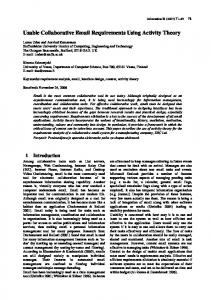
• Structure of an Embedded System: Figure 2.5 depicts our view of the structure of an embedded system. The software part of an embedded system contains, among other things, the computing component and the software representations of the sensors and actuators. Hardware actuators and sensors interact with the corresponding software representations using some communication techniques, such as a Controller Area Network (CAN) bus [66] and they might contain software themselves for various purposes, such as entering a fail-safe state if communication with other system parts fails. The software representations are responsible for processing incoming and outgoing data of the hardware sensors and actuators. The computing component computes the system actions based on the values provided by the software representations. The user interface is responsible for communication with the user via controls and indicators. A communication link, if present, provides an interface to the outside world.
19
Hardware Software
Controls
Software Controls
Software Indicators
UserInterface
Indicators
Computing Component
Sensor 1
Software Actuator 1
Software Sensor x
Software Actuator y
Communication Link
External System
Figure 2.5: Our view on the structure of an embedded system
20
Actuator 1
...
...
...
... Sensor x
Software Sensor 1
Actuator y
Chapter 3 Describing Requirements Patterns This section gives the template used to describe requirements patterns, enumerates the list of patterns, and presents a set of criteria for organizing and classifying the patterns. Additionally, it contains the complete description of all requirements patterns identified thus far.
3.1
Requirements Pattern Template
In contrast to other informal presentation styles for patterns, this paper uses a template similar in style to that used by Gamma et al. [28] in order to facilitate its understanding and application. UML diagrams are used to give structural and behavioral information. As suggested by Ryan [68], we use natural language to supplement diagrams in order to describe important aspects of the patterns as a mean for facilitating the understanding of the requirements from different viewpoints. We modified the original design pattern template in several aspects to address the needs of requirements engineering. Table 3.1 overviews the requirements pattern template. Specifically, the design pattern template has been extended with “Constraints”, “Behavior”, and “Design Patterns” sections. (The sections “Implementation” and “Sample Code” have been removed because they were too specific 21
to software design and implementation.) The “Behavior” section contains sequence and state diagrams that illustrate sample behavior and the “Design Patterns” section contains related design patterns that can be used to further refine the requirements pattern. In contrast, the “Constraints” section contains specification-pattern-based representations of properties of interest. Thus far, our constraints have included representations of two of Dwyer et al.’s [23] most commonly used general specification pattern categories, universality/absence (to capture invariant properties) and response (to capture cause/effect relationships in system behavior). Those constraints provide a template for instantiating properties specific to a UML-modeled system.
22
Pattern Name and Classification:
The pattern name consists of a description of the pattern; the classification provides the purpose of the pattern. Intent: A brief description of the problem(s) that the pattern addresses. Motivation: A description of sample goals and objectives of a system that motivate the use of the pattern. Use-cases and use-case-diagrams describe goals of the pattern application. Applicability: Describe the conditions in which the pattern may be applied. Structure: A representation of the classes and their relationships depicted in terms of UML class diagrams. Behavior: Provides an illustrative representation of scenarios for class and object interaction. Also gives a description of the behavior of the pattern by using sample or highlevel, abstract UML state and sequence diagrams. Participants: Itemizes the classes/objects that are included in the requirements pattern and their responsibilities. Collaborations: Describes how objects and classes interact to carry out the responsibilities given in the “Participants” section. Consequences: Describes how objectives are supported by a given pattern and gives the trade-offs and outcomes of the pattern application. Constraints: This section contains LTL templates and a prose description of these constraints. Thus far, our constraints have included representations of two of Dwyer et al.’s [23] most commonly used general specification pattern categories, universality/absence (to capture invariant properties) and response (to capture cause/effect relationships in system behavior). Design Patterns: Applicable design patterns that can be used to refine the requirements patterns. Also Known As: Lists alternative names for the requirements pattern. Known Uses: Examples of the pattern found in real systems. Related Requirements Lists related requirements patterns and advantages Patterns: /shortcomings that would result from pattern combination. Table 3.1: Requirements pattern template
23
3.2
Requirements Patterns Catalogue Overview
Table 3.2 gives an enumeration of the current requirements patterns in the repository and their respective intentions that have been identified from analyzing several embedded systems. Some of the patterns are applicable to the majority of embedded systems, while other patterns are more specific to individual systems. To determine the applicability of a pattern, the “Intent” section is helpful. More detailed information is provided in the respective complete pattern description. Actuation-Monitor (98): Actuator-Sensor (38):
Communication (91): Controller Decompose (29):
Examiner (56): Fault Handler (63): Mask (73):
Moderator (78): User Interface (82): Watchdog (48):
Increase safety by monitoring actuator behavior for errors. Specify various kinds of sensors and actuators and their relationships to the computing component in an embedded system. Arrange communication between components. Decompose an embedded system into different components according to their responsibilities. Monitor a device and store occurring errors. Specify a fault handler for an embedded system. Reduce the burden on the computing component if many sensors and actuators are present and provide an interface for components accessing the actuators and sensors. Provide an interface to support decoupling of complex subsystems. Specify a user interface that is extensible and reusable. Monitor a device or system conditions and initiate corrective action(s) if a violation is found.
Table 3.2: Current list of requirements patterns for embedded systems
24
3.3
Classifying Requirements Patterns
It is important to classify the patterns in order to facilitate the discovery of related families of patterns. Furthermore, classification enables navigation through the patterns and provides a means for finding a pattern to describe a specific problem. Figure 3.1 gives an overview of how the patterns relate to each other in an informal way similar to the style used by Gamma et al. [28]. The Controller Decompose (29) Pattern is a very general pattern that refers to other patterns for refinement. The Actuator-Sensor (38) and the Fault Handler (63) Patterns point to patterns that can be used to add additional functionality. We offer two orthogonal classification schemes. One possibility is to classify the patterns according to their purposes: creational, structural, or behavioral [28]. • Creational: Patterns for the process object creation. • Structural: Patterns that describe the composition of classes or objects. • Behavioral: Pattern to depict the method of interaction and distribute responsibility of classes or objects. Because most classes in an embedded system application involve physical entities, there is little use for object creation capabilities and therefore, we have not yet identified any creational patterns. Thus, all patterns are either structural or behavioral. Table 3.3 shows a classification of the patterns according to their purpose. The patterns can also be classified according to the following non-functional requirements that they address. • Response Time: “The time within which a system must detect an internal or external event and respond with an action.” [63] • Reliability: “The ability of an item to perform a required function under stated conditions for a stated period of time.” [73] 25
ral v io
al tur
Be
ha
uc Str
Controller Decompose Pattern Actuator-Sensor Pattern Watchdog Pattern Examiner Pattern Fault Handler Pattern Mask Pattern Moderator Pattern User Interface Pattern Communication Pattern Actuation-Monitor Pattern
X X X X X X X X X X
Table 3.3: Pattern classification according to purpose • Fault Tolerance: “The built-in capability of a system to provide correct execution in the presence of a limited number of hardware and software faults.” [73] • Reusability: “The extent to which a module can be used in multiple applications.” [73] • Safety: Minimize the risk to persons or equipment. [21]. • Portability: “Application system reuse where a whole application system is reused by implementing it across a range of different computers and operating systems.” [75] • Extensibility: Maximize flexibility in making changes to the requirements, while minimizing costs for the changes. • Maintainability: “The ease in which the maintenance of a functional unit can be performed in accordance with prescribed requirements.” [73] • User Friendliness: Ease of use and efficiency of the interaction with the user. [30, 73]
This list represents some of the more obvious non-functional requirements that 26
the patterns address; there are potentially many more. See Table 3.4 for a concise summary of this classification of patterns. Positive correlation is denoted with a ‘+’, negative with a ‘-’, and a blank indicates little or no correlations. Due to the nature of non-functional requirements, this classification is subjective. Thus, others may have a different view as to whether a pattern’s impact on the non-functional requirements is considerable enough to be labeled positive or negative. The application of most patterns has a negative effect on the performance of a system due to the added complexity. For example, the Actuator-Sensor (38) Pattern prohibits direct access to member variables of classes; access is only possible through messages. But other properties are usually not negatively affected. Therefore, it is necessary to understand the consequences of applying a pattern so that negative effects of the application do
+ +
+ +
+
+
-
+ +
+ +
+ +
+ +
+
+ + +
+ + + +
+ +
us a
o le ra n ce b il Sa ity fet y Po rta b il it Ex ten y s ib Ma ilit y int a in ab Us ilit er y Fr ie n d li ne ss
+ -
Re
Fa
ult T
it y
b il
lia
Re
Controller Decompose Pattern Actuator-Sensor Pattern Watchdog Pattern Examiner Pattern Fault Handler Pattern Mask Pattern Moderator Pattern User Interface Pattern Communication Pattern Actuation-Monitor Pattern
Re
sp o
ns
eT
im
e
not outweigh the positive effects.
+ + + + +
+ +
Table 3.4: Pattern classification according to non-functional requirements
27
$ # " !
Figure 3.1: Requirements patterns relationships
28
3.4
Requirements Pattern Repository
This section gives a detailed description of the requirements patterns discovered thus far in embedded systems. The names of the requirements patterns are denoted in italics, and the elements of a requirements pattern are given in a san serif font, including class, state, and variable names. Method names and messages are denoted in italics.
3.4.1
Controller Decompose (29): Structural Pattern
Intent: Decompose an embedded system into different components according to their responsibilities. Motivation: This pattern describes important components of an embedded system and should be used early in the system development process. All components presented in this pattern should be addressed by the developer. Leaving out one component might make the system difficult and expensive to extend in future, or even require a total redesign. Figure 3.2 shows a use-case diagram of the Controller Decompose (29) Pattern. Use-Case:
System running
Actors:
None
Description: This use-case represents the system when it is functioning. Includes:
Receive input values, Interact with user, Set output values, Communicate with external entities
29
Figure 3.2: UML use-case diagram of the Controller Decompose (29) Pattern
30
Sensor
Receive input values
Controller_Decompose - use case.dom
External entity
Communicate with external entities
Use in safe mode
System running
Interact with user
System Boundary
User
Set output values Actuator
Use-Case:
Receive input values
Actors:
Sensor
Description: The system receives values from sensors, either by polling the sensors or the sensors actively send the values. Includes:
-
Use-Case:
Set output values
Actors:
Actuator
Description: The system sends values to the actuators. Includes:
-
Use-Case:
Interact with user
Actors:
User
Description: Read user controls and activate indicators. Includes:
-
Use-Case:
Use in safe mode
Actors:
User
Description: Special case of the use-case System running. System offers basic functionality due to errors that have occurred. The exact level of functionality is systemdependent. Includes:
-
Use-Case:
Communicate with external entities
Actors:
External entity
Description: Offer communication capabilities for external entities. Includes:
-
Applicability: The Controller Decompose (29) Pattern is applicable • in any embedded system. Only a high-level decomposition of the system structure is given.
31
Structure: Figure 3.3 gives an overview of the structure of the Controller Decompose (29) Pattern. Each component in this diagram is a structure of hardware and software responsible for performing a specific task. Experience has shown that the system should be modeled to never exceed an utilization of fifty percent. If the utilization does exceed fifty percent, then it is likely that the system will not be able to process information reliably under any circumstances [25].
FaultHandler Component uses warning functionality Input Component
get values
interact with other entities Communication Component
handle faults
Computing Component
interact with user
UserInterface Component
set values
Output Component
provide timing information
Timing Component
Figure 3.3: UML package diagram of the Controller Decompose (29) Pattern
Behavior: This abstract pattern gives no behavioral information, but instead refers to other requirements and design patterns that refine behavior in the respective individual sections.
32
Participants: • ComputingComponent: Central component of an embedded system, computes the required outputs from the inputs and the actual state of the system. • InputComponent: Contains sensors of the system. • OutputComponent: Contains actuators of the system. • FaultHandlerComponent: Provides fault handling capabilities for the system. • CommunicationComponent: Provides communication to the system environment, including other embedded systems and specialized diagnostic units. • UserInterfaceComponent: Responsible for interaction with the user and for the consistency of the user inputs. • TimingComponent: Timing component of the system.
Collaborations: • The ComputingComponent is responsible for determining required actions based on the values of the input and output components and the current system state. • The InputComponent represents sensors of the system; the ComputingComponent queries the sensors when it needs an update of the values or receives values from active sensors. • The OutputComponent represents actuators of the system, the ComputingComponent can set their states and values. • The CommunicationComponent provides an interface for the system to the external environment. Through this interface, system states and conditions can be queried or specified and the error list of the fault handler can be obtained. 33
Depending on the specific system, the communication component can be designed to perform additional actions, from reading values to fully controlling the system. • The UserInterfaceComponent is a special collection of sensors and actuators that interact with the user. These sensors and actuators are in a separate component because user interaction usually differs from the interaction with other sensors and actuators. For example, timing aspects of user interactions are usually not tightly constrained. • In most embedded systems, the TimingComponent is implemented in hardware. The main task is to offer a reliable timing information under any condition.
Consequences: 1. When this pattern is applied, it provides a basic system structure that must be further refined. 2. Components considered to be unnecessary should still be considered in the system development process to increase the extensibility and reusability of the system. For example, if an embedded system does not have a user interface, but the requirements of a possible future user interface are taken into considerations during the development process, then it will be easier to extend the system in future with a user interface.
Constraints: Due to the abstract nature of this pattern, it does not give LTL constraints, but the requirements patterns referred to in the Behavior field contain constraints for the respective components.
34
Design Patterns: • Layered Design Pattern [22]: How to organize domains into a hierarchy. • Five-Layer Design Pattern [22]: Specific version of the Layered Design Pattern [22]. • CommunicationComponent: – Serial Port Design Pattern [25]: This design pattern describes a class that completely encapsulates the interface of a serial port device. – High Speed Serial Port Design Pattern [25]: The high speed variant of the Serial Port Design Pattern offers DMA (Direct Memory Access) capabilities. • Timing Component: – Timer Design Patterns [25]: Applicable design patterns for timer management are introduced.
Also Known As: To be determined. Known Uses: To be determined. Related Requirements Patterns: • OutputComponent:
35
– Communication (91) Requirements Pattern: Arrange communication between components. – Actuator-Sensor (38) Requirements Pattern: Specify various kinds of sensors and actuators and their relationships to a computing component in an embedded system. – Actuation-Monitor (98) Requirements Pattern: Increase safety by monitoring actuator behavior for errors. – Mask (73) Requirements Pattern: Reduce the burden on the computing component if many sensors and actuators are present and provide an interface for components accessing the actuators and sensors. – Moderator (78) Requirements Pattern: Provide an interface to support decoupling of complex subsystems. • InputComponent: – Communication (91) Requirements Pattern: Arrange communication between components. – Actuator-Sensor (38) Requirements Pattern: Specify various kinds of sensors and actuators and their relationships to a computing component in an embedded system. – Mask (73) Requirements Pattern: Reduce the burden on the computing component if many sensors and actuators are present and provide an interface for components accessing the actuators and sensors. – Moderator (78) Requirements Pattern: Provide an interface to support decoupling of complex subsystems. 36
• FaultHandlerComponent: – Fault Handler (63) Requirements Pattern: Specify a fault handler for an embedded system. – Watchdog (48) Requirements Pattern: Monitor a device or system conditions and initiate corrective action(s) if a violation is found. – Examiner (56) Requirements Pattern: Monitor a device and store occurring errors. • UserInterfaceComponent: – User Interface (82) Requirements Pattern: Specify a user interface that is extensible and reusable.
37
3.4.2
Actuator-Sensor (38): Structural Pattern
Intent: Specify various kinds of sensors and actuators and their relationships to the computing component in an embedded system. Motivation: Embedded systems usually have various kinds of sensors and actuators. These sensors and actuators are all either directly or indirectly connected to the computing component. Although many of the sensors and actuators are physically different, their behavior is sufficiently similar to be structured into a pattern. The Actuator-Sensor (38) Pattern shows how to specify the sensors and actuators for a system. Most sensors and actuators only set or receive a value that has the data type boolean, integer, or real. But even for more complex sensors and actuators, like a radar unit, this pattern is useful to be able to query the operational state (boolean check that indicates whether the component is functioning correctly) and other conditions with the same interface. This pattern also takes into account that attributes should only be accessed through defined methods in order to ensure system integrity and increased reusability through information hiding. The Actuator-Sensor (38) Pattern uses a pull mechanism (explicit request for information) for passive sensors and a push mechanism (broadcast of information) for active sensors. (Refer to the Design Patterns field for more detail on these strategies.) Figure 3.4 shows a use-case diagram of the Actuator-Sensor (38) Pattern. Two goals of this pattern are either to receive a value or to set a value. Use-Case:
System running
Actors:
None
Description: This use-case represents the system when it is functioning. Includes:
Receive input values, Set output values
38
Actuator-Sensor_-_Use_Case.dom Embedded System Boundary System running
Receive input values
Set output values
Sensor
Actuator
Figure 3.4: UML use-case diagram of the Actuator-Sensor (38) Pattern
Use-Case:
Receive input values
Actors:
Sensor
Description: The system receives values from sensors, either by polling the sensors or the sensors actively send the values. Includes:
-
Use-Case:
Set output values
Actors:
Actuator
Description: The system sends values to actuators. Includes:
-
This pattern relates to the four-variable model by Parnas and Madey [60] shown in Figure 3.5. The monitored variables (MON) are physical quantities measured by the physical representations of the active and passive sensors. The IN-relation transforms the MON to INPUT and represents the transformation of the values of the physical sensors to their software representations. The behavior of the computing component is defined by the SOFT relationship that maps INPUT to OUTPUT. The OUTPUT is then transformed from the software actuators to their physical representations with the controlled variables (CON). Overall, the relations IN, SOFT,
39
and OUT have to perform the requirements of the system, denoted by the REQrelationship that maps from the monitored to the controlled variables. REQ
MON
IN
CON
OUT
INPUT
OUTPUT SOFT
Figure 3.5: Four-variable model [60]
Applicability: The Actuator-Sensor (38) Pattern is applicable • in all embedded systems, and particularly useful when many actuators and sensors are present.
Structure: A UML class diagram for the Actuator-Sensor (38) Pattern can be found in Figure 3.6. Four different types of sensors and actuators can be found in this pattern. The boolean, integer, and real classes represent the most common types of sensors and actuators. The complex classes are sensors or actuators that use values that cannot be easily represented in terms of primitive data types, such as a radar device. Nonetheless, these devices should still inherit the interface from the abstract classes since they should have basic functionalities, such as querying the operation states. Behavior: Figure 3.7 shows a UML sequence diagram for an example of the ActuatorSensor (38) Pattern in a climate control system. The ComputingComponent queries
40
Figure 3.6: UML class diagram of the Actuator-Sensor (38) Pattern 1
Concrete Boolean Actuator1
Abstract Boolean Actuator
sets values at
Abstract Complex Actuator
Concrete ActiveComplex Sensor1
Concrete ActiveReal Sensor1
Concrete ActiveInteger Sensor1
Concrete ActiveBoolean Sensor1
Concrete Complex Actuator1
Abstract Real Actuator
Concrete Real Actuator1
Abstract Actuator
Concrete Integer Actuator1
Abstract Integer Actuator
0..*
Abstract ActiveComplex Sensor
1
Abstract ActiveReal Sensor
Abstract ActiveSensor
0..*
Computing Component
sets values at
1
Abstract ActiveInteger Sensor
...
Abstract ActiveBoolean Sensor
ConcretePassive Complex Sensor1
ConcretePassive Real Sensor1
ConcretePassive Integer Sensor1
ConcretePassive Boolean Sensor1
Abstract PassiveComplex Sensor
Abstract PassiveInteger Sensor
...
Abstract PassiveBoolean Sensor
Abstract PassiveReal Sensor
...
0..*
reads values from
...
Abstract PassiveSensor
...
...
...
...
...
...
... ...
41
a sensor (a passive temperature sensor) and an actuator (a radiator valve) to check the operational state for diagnostic purposes before reading or setting a value. The messages “Set Physical Value” and “Get Physical Value” are not messages between objects. Instead, they describe the interaction between the physical devices of the system and their software representations. In the lower part of the diagram (below the bold horizontal line) the TemperatureSensor reports that the operational state is zero. The ComputingComponent then sends the error code for a temperature sensor failure to the FaultHandler that will decide how this error affects the system and what actions are required. Participants: • ComputingComponent: The central component of the system; it reads data from the sensors and computes the required response for the actuators. • AbstractPassiveSensor {abstract}: Defines an interface for passive sensors. • AbstractPassiveBooleanSensor {abstract}: Defines passive boolean sensors. • AbstractPassiveIntegerSensor {abstract}: Defines passive integer sensors. • AbstractPassiveRealSensor {abstract}: Defines passive real sensors. • AbstractPassiveComplexSensor {abstract}: Complex passive sensors have the basic functionality of the AbstractPassiveSensor class, but additional, more elaborate, methods and attributes need to be specified. • AbstractActiveSensor {abstract}: Defines an interface for active sensors. • AbstractActiveBooleanSensor {abstract}: Defines active boolean sensors. • AbstractActiveIntegerSensor {abstract}: Defines active integer sensors. • AbstractActiveRealSensor {abstract}: Defines active real sensors. 42
Figure 3.7: UML sequence diagram example of the Actuator-Sensor (38) Pattern
43
{TemperatureSensor.OperationState = 0}
{TemperatureSensor.OperationState = 1}
Fault Handler
Store Error
Get Operation State
Get Value
Radiator Valve Actuator
Set Value
Get Operation State
Get Physical Value
Computing Component
Get Operation State
Temperature Sensor
Set Physical Value
Sensor Input Device Temperature Sensor
Actuator Output Device Radiator Valve
• AbstractActiveComplexSensor {abstract}: Complex active sensors have the basic functionality of the AbstractActiveSensor class, but additional, more elaborate, methods and attributes, need to be specified. • AbstractActuator {abstract}: Defines an interface for actuators. • AbstractBooleanActuator {abstract}: Defines boolean actuators. • AbstractIntegerActuator {abstract}: Defines integer actuators. • AbstractRealActuator {abstract}: Defines real actuators. • AbstractComplexActuator {abstract}: Complex actuators also have the base functionality of the AbstractActuator class, but additional, more elaborate methods and attributes need to be specified. • AbstractPassiveBooleanSensor1, AbstractPassiveIntegerSensor1, AbstractPassiveRealSensor1,
AbstractPassiveComplexSensor1,
AbstractActiveIntegerSensor1,
AbstractActiveBooleanSensor1,
AbstractActiveRealSensor1,
AbstractActiveCom-
plexSensor1, AbstractBooleanActuator1, AbstractIntegerActuator1, AbstractRealActuator1, AbstractComplexActuator1: Concrete example classes defining the interfaces for sensors and actuators that can be instantiated.
Collaborations: • When the ComputingComponent needs to update the value of a PassiveSensor, it queries the sensors, requesting the value by sending the corresponding message. • ActiveSensor’s are not queried. They initiate the transmission of sensor values to the computing unit, using the appropriate method to set the value in the ComputingComponent. They send a life tick at least once during a specified time frame in order to ensure the active sensors have not failed. 44
• When the ComputingComponent needs to set an output value, it sends the value to the actuator, which subsequently performs the actuation. • The ComputingComponent can query and set the operational state of the sensors and actuators using the appropriate methods. If an operational state is found to be zero, then the error is sent to the FaultHandler who is responsible for handling error messages, such as starting a more elaborate recovery mechanism or a backup device. If no recovery is possible, then the system can use the last known value for the sensor or a default value. • The ActiveSensor’s offer methods to add or remove the addresses or address ranges of the components that need to receive update messages in case of a value change. Consequences: 1. Sensor and actuator classes have a common interface. Therefore, the readability, understandability, and maintainability of the system is improved. 2. Class attributes can only be accessed through messages. The class decides in turn whether to accept the message. For example, if a value of an actuator is set above a maximum value, then the actuator class may not accept the message, or it might use a default maximum value instead. Constraints: • Response Pattern: If a component fails, then the operational state of the component should be eventually set to zero. ¤(Component.‘‘Failure occurred’’ → ♦(Component.‘‘Operational state false’’)) 45
• Response Pattern: When the value of an active sensor changes, the computing component should receive the updated value. ¤(ActiveSensor.‘‘Value change’’ → ♦(‘‘Send updated value to the ComputingComponent’’)) • Response Pattern: When an active sensor times out, the error message should be sent to the fault handler. ¤(ActiveSensor.‘‘timeout’’ → ♦(‘‘Report timeout to fault handler’’))
Design Patterns: • Factory Method Design Pattern [28]: This pattern and related ones can be used to handle the object creation of the actuators and sensors. • Observer Design Pattern [28]: Use this pattern for active sensors to notify dependents if the sensor values change. • Feature Coordination Design Patterns [25]: These patterns describe different strategies to handle message sequences for the communication with actuators and sensor. • Data Bus Design Pattern [22]: Describes push and pull strategies for reading sensor values.
46
Also Known As: To be determined. Known Uses: To be determined. Related Requirements Patterns: • Controller Decompose (29) Requirements Pattern: A global view on the relation of the sensors and actuators to the computing components and other components in a system is described. • Communication (91) Requirements Pattern: Arrange communication between the computing component and actuators and sensors of a system. • Actuation-Monitor (98) Requirements Pattern: The Actuation-Monitor (98) Pattern shows how to use redundant sensors to monitor the actuation of a device.
47
3.4.3
Watchdog (48): Behavioral Pattern
Intent: Monitor a device or system conditions and initiate corrective action(s) if a violation is found. Motivation: Embedded systems typically have tight timing constraints. Providing a mechanism to assure a component is reacting or specific constraints on the system are not violated is the objective of the Watchdog (48) Pattern. A watchdog is a mechanism for responding to conditions that might violate safety, uncovering those conditions through mechanisms, such as receiving messages from other subsystems on a periodic or sequence-keyed basis [21]. If a service to the watchdog occurs too late or out of sequence, then the watchdog initiates some corrective action, such as a reset, a shutdown, sending an alarm to notify an operator or other personnel, or a more elaborate error-recovery mechanism. Figure 3.8 shows a use-case diagram of the Watchdog (48) Pattern. Use-Case:
System running
Actors:
None
Description: This use-case represents the system when it is functioning. Includes:
Handle faults
Use-Case:
Detect violations
Actors:
None
Description: Devices not responding in a specific time or violations of system constraints are detected. Includes:
Start recovery action
48
Watchdog_Use_Case_Diagram.dom System Boundary
Detect violations
Diagnose faults
Technician
Detect faults Start recovery action
Handle faults
System running
Figure 3.8: UML use-case diagram of the Watchdog (48) Pattern
Use-Case:
Diagnose faults
Actors:
Technician
Description: Special case of the use-case Handle faults. The system offers extended diagnostic functions instead of handling faults to identify the source of the fault(s). Includes:
-
Use-Case:
Detect faults
Actors:
None
Description: The system offers fault detection functionality. Includes:
Detect violations
Use-Case:
Handle faults
Actors:
None
Description: Initiate corrective actions if needed. Includes:
Detect faults, Start recovery action
49
Use-Case:
Start recovery action
Actors:
None
Description: In case of a detected violation start recovery action. Includes:
-
Applicability: The Watchdog (48) Pattern is applicable • in systems that have high safety requirements.
Structure: The class diagram for the Watchdog (48) Pattern can be seen in Figure 3.9. The Watchdog interacts with the FaultHandler to store errors and initiates recovery actions at the monitored Device, such as a reset.
to ts r po re
0..*
Watchdog
monitors and initiates recovery 0..*
FaultHandler sends errors to
1
1
0..*
Device 1
Figure 3.9: UML class diagram of the Watchdog (48) Pattern
Behavior: Figure 3.10 and Figure 3.11 show state diagrams for the Watchdog class. The first one represents a state diagram for a watchdog that is waiting for a periodic 50
service (denoted by an Update() message) by a Device, the latter one for a watchdog that periodically checks if certain system conditions are violated. Figure 3.12 shows a sequence diagram where a watchdog of the first type detects a timeout of the Device, initiates a reset, and sends the error to the FaultHandler.
Update()[WDTimerThreshold]/
Violation do/Start recovery action do/Send error message
Figure 3.10: UML state diagram of the Watchdog (48) Pattern (1)
Participants: • Watchdog: Watchdog monitoring the device. The Watchdog can be implemented in hardware to protect it from software faults. • Device: Device monitored by the Watchdog. • FaultHandler: Central fault handler of the system.
Collaborations: • The Watchdog is waiting for a message from a Device or monitors certain system conditions on a periodic basis. If this message does not arrive on time or a 51
WDStart()[]/WDTimer:=0 Idle
Counting WDStop()[]/ [WDTimer=Threshold] /
[No violation found]/WDTimer:=0
Violation [Violation found]/ Check do/Start recovery action do/Check conditions do/Send error message
Figure 3.11: UML state diagram of the Watchdog (48) Pattern (2)
condition is violated, then the watchdog performs recovery actions, such as resetting a device or shutting the system down and reports the error to the FaultHandler. • The FaultHandler handles the error message and may initiate additional actions.
Consequences: 1. If a watchdog monitors a device on a periodic basis, then the device has to send life ticks periodically to the watchdog. 2. A fault handler should be present to handle error messages from the watchdog. 3. The system must contain a reset operation or a more elaborate error recovery mechanism that the watchdog can perform in case of a violation.
52
Figure 3.12: UML sequence diagram example of the Watchdog (48) Pattern
53
Device times out, the watchdog resets the device and reports the error the fault handler.
Watchdog
StoreError("Device timed out")
Reset()
Update()
Update()
Update()
Device
FaultHandler
Constraints: • Response Pattern: If there is a violation, then the watchdog should eventually recognize the violation. ¤(‘‘Physical Violation’’ → ♦(‘‘Watchdog Violation’’)) • Response Pattern: If a violation of a system constraint is found, then the watchdog should start the corresponding recovery action appropriate to the system being modeled (e.g., begin error recovery, reset the device, shut down). ¤(‘‘Watchdog Violation’’ → ♦(‘‘Start recovery action’’)) • Response Pattern: When a violation is found, a message containing the appropriate error code should be sent to the fault handler (indicated by the keyword sent). ¤(‘‘Watchdog Violation’’ → ♦(‘‘Report error to fault handler’’))
Design Patterns: • Watchdog Design Pattern [22]: Describes more implementation specific details about the watchdog, such as implementation strategies.
Also Known As: To be determined.
54
Known Uses: To be determined. Related Requirements Patterns: • Examiner (56) Requirements Pattern: Describes similar functionality, but does not perform recovery actions. • Fault Handler (63) Requirements Pattern: Stores and handles error messages from the watchdog.
55
3.4.4
Examiner (56): Behavioral Pattern
Intent: Monitor a device and store occurring errors. Motivation: The Examiner (56) Pattern is similar to the Watchdog (48) Pattern. The main difference is that the watchdog pattern performs corrective actions, whereas the examiner only reports errors to the fault handling component and the responsibility to take further actions lies with the fault handler. Hence, the examiner is usually implemented in software and not hardware because it is less important to system safety. Nevertheless, the error log entries by the examiner are useful for system diagnostic purposes. Failures can be found before they affect the system safety by analyzing the error log. Use-Case:
System running
Actors:
None
Description: This use-case represents the system when it is functioning. Includes:
Handle faults
Use-Case:
Detect violations
Actors:
None
Description: Devices not responding in a specific time or violations of system constraints are detected. Includes:
-
Use-Case:
Diagnose faults
Actors:
Technician
Description: Special case of the use-case Handle faults. The system offers extended diagnostic functions instead of handling faults to identify the source of the fault(s). Includes:
-
56
Examiner_Use_Case_Diagram.dom System Boundary
Diagnose faults
Detect violations
Detect faults Start recovery action
Handle faults
System running
Figure 3.13: UML use-case diagram of the Examiner (56) Pattern
Use-Case:
Detect faults
Actors:
None
Description: The system offers fault detection functionality. Includes:
Detect violations
Use-Case:
Handle faults
Actors:
None
Description: Initiate corrective actions if needed. Includes:
Detect faults, Start recovery action
Use-Case:
Start recovery action
Actors:
None
Description: In case of a detected violation start recovery action. Includes:
-
57
Technician
Applicability: The Examiner (56) Pattern is applicable • when monitoring of non-critical devices is needed. Do not use the Examiner (56) Pattern when • the violations detected by the examiner are affecting system safety. The examiner is not protected from software faults and the Watchdog (48) Pattern should be used, instead, to ensure maximum system safety.
Structure: The class diagram of the Examiner Pattern can be seen in Figure 3.14, where the only difference to the Watchdog (48) Pattern is that the Examiner Pattern does not perform a recovery action.
1
sends errors to
ts or p re
FaultHandler
0..*
1
0..*
monitors
Examiner
0..*
Device 1
Figure 3.14: UML class diagram of the Examiner (56) Pattern
Behavior: Figure 3.15 shows the state diagram of an Examiner, expecting service (denoted by an Update() message) from a Device on a periodic basis. In contrast to the Watchdog 58
(48) Pattern, no recovery action is performed if a violation is detected. Figure 3.15 shows an Examiner checking periodically certain system conditions for violations. Figure 3.17 denotes a sequence diagram where the Examiner detects a timeout of a device and reports the error to the FaultHandler. With the FaultHandler lies the responsibility to initiate safety actions.
Update()[ExTimerThreshold]/ExTimer:=0, FaultHandler.StoreError(TimeOut)
Figure 3.15: UML state diagram of the Examiner (56) Pattern (1)
ExStart()[]/ExTimer:=0 Idle
Counting ExStop()[]/ [ExTimer=Threshold] /
[No violation found]/ExTimer:=0
[Violation found]/ Violation do/Send error message
Check do/Check conditions []/
Figure 3.16: UML state diagram of the Examiner (56) Pattern (2)
59
Figure 3.17: UML sequence diagram example of the Examiner (56) Pattern
60
Device times out. The examiner detects the timeout and reports the error to the fault handler.
Examiner
StoreError("Device timed out")
Update()
Update()
Update()
Device
FaultHandler
Participants: • Examiner: The component that monitors Device. • Device: Device monitored by the Examiner. • FaultHandler: Central fault handler of the system.
Collaborations: • The Examiner is waiting for a message from a Device or monitors certain system conditions on a periodic basis. If this message does not arrive on time or a condition is violated, then the Examiner reports the error to the FaultHandler. • The FaultHandler handles the error message and with it lies the responsibility to initiate recovery actions.
Consequences: 1. If an examiner monitors a device on a periodic basis, then the device has to send life ticks periodically to the examiner. 2. A fault handler should be present to handle the error messages from the examiner.
Constraints: • Response Pattern: If there is a violation, then the examiner should eventually recognize the violation. ¤(‘‘Physical Violation’’ → ♦(‘‘Examiner Violation’’))
61
• Response Pattern: When a violation is found, a message containing the appropriate error code should be sent to the FaultHandler (indicated by the keyword sent). ¤(‘‘Examiner Violation’’ → ♦(‘‘Report error to fault handler’’))
Design Patterns: To be determined. Also Known As: To be determined. Known Uses: To be determined. Related Requirements Patterns: • Watchdog (48) Requirements Pattern: This patterns has similar functionality, but performs recovery actions if a violation is detected. • Fault Handler (63) Requirements Pattern: The fault handler handles error messages from the examiner.
62
3.4.5
Fault Handler (63): Behavioral Pattern
Intent: Specify a centralized fault handler for an embedded system. Motivation: Fault handling is essential for embedded systems. Embedded systems frequently need to determine what responses are necessary to recover from errors. Consider a flight control system in an airplane, where the system should never shut down completely in response to an error. The system has to decide if it should perform a partial shutdown and offer basic functionality, or if the error is no threat to system safety and logging is sufficient. This fault handler must offer the possibility for other devices to read the error log. But it should also have access to a user interface to signal that errors have occurred. An important function of the fault handler is to send the system into different safety states depending on the severity of the error. These safety states have to be implemented in the computing component, such as the operation for performing an emergency stop. If an error is reported to the fault handler justifying this action, then the fault handler will activate this state. Therefore, the fault handler acts as a centralized coordinator for safety monitoring and, hence, control of system recovery. The following inputs are usually captured [21]: • Timeout messages by watchdogs, examiners, or monitors. • Assertions of software errors. • Built-in-tests (BITs) that run on a periodic or continuous basis. The centralized safety control facilitates the verification and validation of the safety measures and eases the reuse of the fault handler in different systems.
63
Figure 3.18 gives the use-case diagram for the Fault Handler (63) Pattern, with the major goals being to detect and to handle faults. Use-Case:
System running
Actors:
None
Description: This use-case represents the system when it is functioning. Includes:
Handle faults, Interact with user
Use-Case:
Use in safe mode
Actors:
User
Description: Special case of the use-case System running. System offers basic functionality due to errors that have occurred. The exact level of functionality is systemdependent. Includes:
-
Use-Case:
Interact with user
Actors:
User
Description: Read user settings and activate indicators. Includes:
-
Use-Case:
Handle faults
Actors:
None
Description: Initiate corrective actions if needed. Includes:
Detect faults
Use-Case:
Diagnose faults
Actors:
Technician
Description: Special case of the use-case Handle faults. The system offers extended diagnostic functions instead of handling faults to identify the source of the fault(s). Includes:
-
Use-Case:
Detect faults
Actors:
None
Description: The system offers fault detection functionality. Includes:
-
64
Figure 3.18: UML use-case diagram for the Fault Handler (63) Pattern
65
User Use in Safe Mode
Interact with user
System running
Embedded System Boundary
FaultHandler_-_Use-Case.dom
Handle faults
Detect faults
Diagnose faults
Technician
Applicability: The Fault Handler (63) Pattern is applicable • in embedded systems where fault handling is to be centralized.
Structure: The UML class diagram of the Fault Handler (63) Pattern can be seen in Figure 3.19. The FaultHandler sends messages to the UserInterface to activate warning levels and sends the ComputingComponent into different safety states. For every safety state defined in the requirements, an operation in the ComputingComponent is needed. The safety states are listed in the Behavior field. The FaultHandler also receives error messages from Watchdogs, Examiners, and Monitors. The Device class represents possible devices in the system that also send error messages to the FaultHandler. Depending on the safety measures and policies defined, the FaultHandler decides what action to take, for example, such as activating a FailSafeDevice. Behavior: Figure 3.20 shows the state diagram of the ComputingComponent of the Fault Handler (63) Pattern. The state diagram shows which states are possible and what messages activate them. Not all of the states are needed in every system. For example, ABS systems generally do not have partial shutdown states because the system constraints require that an inactive system should not affect the basic functionality of the brakes. Therefore, an emergency stop where the ABS system cuts power immediately is sufficient. These states are defined for the class ComputingComponent; when an error occurs, the FaultHandler decides which state is appropriate and sends the respective message to the ComputingComponent to activate the corresponding state if needed. The FaultHandler also activates the UserInterface to notify the system user of the current system state. The definitions for the possible system states are as 66
controls 1
ComputingComponent
FaultHandler
1
1 1 1
0..*
co n
1
tro
ls
0..*
0..*
monitors
1
0..*
backs up
Device 1
monitors
0..*
reports to
Watchdog/ Examiner
UserInterface 1
sends errors to
ts or p re
sends values to
1
1
FailSafeDevice
0..*
Monitor
0..*
Figure 3.19: Structural Diagram for the Fault Handler (63) Pattern
follows [21]: • Normal Behavior: This state captures the system when no errors have occurred and it is functioning normally. • Manual/External: In this state, the system is controlled by an external entity, such as a diagnostic device. • Production Stop: This state is useful, for example, when a human enters a hazardous area. The system should be able to complete its current task and secure the environment, but it should shutdown as soon as possible. • Protection Stop: Ceases operation immediately, but does not turn off power. This state is appropriate, for example, when a machine needs to be stopped, but a device should continue to operate to avoid hazardous situations. For example, a cooling device should remain working even in case of a system malfunction. 67
• Partial Shutdown: The system only offers basic functionality; for example, medical devices may remain in a monitoring state. • Hold: No functionality is provided in this state, but safety actions are taken; for example, a rocket self-destructs in the case of abnormal functions. There is no outgoing transition from this state; a system can only be reactivated by a complete restart. • Initialize: In this state, the system initializes itself. • Power Off: The system might be connected to a power supply in this state, but is not yet activated. For example, a television set can operate in a standby mode. Furthermore, an emergency stop can be performed by the system. This stop state is not modeled as a separate state because this action takes the system to the PowerOff state immediately. Participants: • FaultHandler: Fault handler of the system. Contains safety measures and policies. • ComputingComponent: Central computing component of the system. • UserInterface: Class offering functionality to notify the user about errors. • Device: Component representative for a number of possible devices in the system. • Watchdog/Examiner: Watchdog or examiner in the system. • Monitor: Possible monitor monitoring the Device.
68
Figure 3.20: UML state diagram of the ComputingComponent in the Fault Handler (63) Pattern
69
Production Stop
ShutdownPdS()[]/
[]/
Protection Stop
do/complete current task
ShutdownPtS()[]/
Manual/External Control
Reset()[]/
ShutdownPtS()[]/
PowerOff()[]/
PowerOff()[]/
[Initialization failed]/
do/Initialize system
Initialize
ShutdownPartial()[]/
do/Compute
Normal Behavior
Reset()[]/
Partial Shutdown
ShutdownPdS()[]/
Manual()[]/
Automatic()[]/
Hold
do/Cut power
PowerOff
PowerOn()[]/
Hold()[]/
ShutdownES()[]/
[Initialization succeeded]/
• FailSafeDevice: Possible backup component for the Device.
Collaborations: • The FaultHandler receives error messages and stores those messages in an error log. Furthermore, the FaultHandler decides, depending on the safety measures and policies, if a fail-safe state in the ComputingComponent should be entered, or whether the user interface or recovery device should be activated. • Watchdog, Examiner, and/or Monitor monitor the device and report violations to the FaultHandler. • FailSafeDevice is activated to recover from faults. • The UserInterface gets activated by the FaultHandler.
Consequences: 1. Required safety states have to be implemented in the ComputingComponent. 2. Only one fault handler should exist in the system and should handle all error messages to avoid inconsistent handling of faults [21]. 3. The fault handler is one of the critical elements for system safety. Therefore, during the development process of this component, techniques should be used that result in a high assurance of the software component, such as formal methods and thorough testing. 4. Hardware and software redundancies exist in the system, thus meaning higher system costs. 5. Overall safety of the system can significantly be improved by the centralized fault handling component. 70
Constraints: • Absence Pattern: If system initialization fails, then the system should remain in a powered-off state. Therefore, the system should never be in a state where the initialization failed and the system power is on. ¤(!(‘‘Initialization failed’’ && ‘‘System power on’’)) • Response Pattern: When an error message is sent to the fault handler, it should process the error and, depending on the error classification, perform the predefined recovery action as a result of the error. This action can range from “Do nothing” to “Perform emergency shutdown of the system”. ¤(‘‘Error reported to fault handler’’ → ♦(‘‘Start defined recovery action’’)) • Response Pattern: When an error message is sent, it should be stored in an error log for system diagnosis purposes. ¤(‘‘Error reported to fault handler’’ → ♦(‘‘Store error in error log’’)) • Response Pattern: If an error message is sent to the fault handler, then it should activate the appropriate user interface warning level if required. ¤(‘‘Error reported to fault handler’’ → ♦(‘‘Activate appropriate user interface warning level’’))
71
• Response Pattern: If some device, such as a diagnostic device, requests the current error list, then the error list should be sent to the device. ¤(‘‘Error list requested from fault handler’’ → ♦(‘‘Return list of errors in error log’’))
Design Patterns: • Singleton Design Pattern [28]: Assure that only one fault handler exists in the system. • Strategy Design Pattern [28]: Encapsulate algorithms for the safety states and make them interchangeable.
Also Known As: To be determined. Known Uses: To be determined. Related Requirements Patterns: • Controller Decompose (29) Requirements Pattern: This requirements pattern describes how the fault handler relates to other components in a system. • User Interface (82) Requirements Pattern: This pattern can be used for the user interface to signal a user the current system state.
72
3.4.6
Mask (73): Structural Pattern
Intent: Reduce the burden on the computing component if many sensors and actuators are present and provide an interface for components accessing the actuators and sensors. Motivation: If many sensors and actuators are present in an embedded system, all messages sent can impose a heavy burden on the system resulting in timeouts and/or unpredictable behavior of the entire system [25]. This situation can be ameliorated by designing a class that is responsible for interacting with the sensors and actuators that serve the same function. The Mask class can coordinate functions, such as the distribution of a new value to all actuators. The advantage is that the computing unit is able to confirm specific actions that are handled by the mask faster. Applicability: The Mask (73) Pattern is applicable • when actuators and sensors can be clustered into packages responsible for performing a common task, such as sensors and actuators responsible for controlling the temperature of the same room. • when a simplified interface can be useful. If the system never uses the mask, then the complexity this pattern adds and the resources needed are superfluous. • only for sensors and actuators. Use the Moderator (78) Pattern to provide an interface for devices or subsystems. Structure: The class diagram of the Mask (73) Pattern is given in Figure 3.21. In this class diagram, the ComputingComponent can either access the sensors and actuators 73
directly or through the Mask component.
Abstract Passive Sensor
Concrete Sensor
0..*
controls
1
* controls
1
Mask *
0..* 1
Computing Component 1 controls
Concrete Actuator
0..*
Abstract Actuator
Figure 3.21: UML class diagram of the Mask (73) Pattern
Behavior: Figure 3.22 shows a sequence diagram example for the Mask (73) Pattern. A room temperature controller queries the Mask that is controlling temperature sensors and radiator valves in one room. Because all the radiator valves must have the same setting, it is sufficient to take the value of one of the valves, for example, the first one. The room temperature controller sends a message to the Mask to set a new temperature. The Mask then sets all the values for each radiator valve, in this example only two exist. The temperature controller has only one message to send and is ready
74
earlier to handle other messages. With this access to the radiator valves the system becomes easier to adapt. If radiator valves are added or removed, then only the responsible Mask must be notified about the change. Participants: • AbstractPassiveSensor {abstract}: Defines an interface for the ConcreteSensor, this class was taken from the Actuator-Sensor (38) Pattern. • ConcreteSensor: A sensor of the system. • AbstractActuator {abstract}: Defines an interface for the ConcreteActuator, this class was taken from the Actuator-Sensor (38) Pattern. • ConcreteActuator: An actuator of the system. • ComputingComponent: Computing component of the system. • Mask: Provides an interface to access sensors and actuators.
Collaborations: • The Mask class offers an interface to access multiple actuators and sensors. • It receives the messages from the ComputingComponent, processes them and sends messages to the actuators and sensors affected by the messages. • Neither the actuators and sensors nor the ComputingComponent have to know explicitly about the presence of the Mask.
Consequences: 1. It provides a common interface for accessing actuators and sensors. 75
2. This pattern helps to meet timing constraints by reducing the burden on the computing component. Complex operations can be put in the mask so that the computing component is unloaded from these operations earlier.
Constraints: • None
Design Patterns: • Facade Design Pattern [28]: Describes a similar idea of how to define a high-level interface for a subsystem. Describes more implementation specific details, such as sample code.
Known Uses To be determined. Related Requirements Patterns: • Moderator (78) Requirements Pattern: Describes similar technique, but is intended to be used to decouple a subsystem. • Actuator-Sensor (38) Requirements Pattern: This pattern can be used for the sensors and actuators in the system.
76
Figure 3.22: UML sequence diagram of the Mask (73) Pattern
77 SetTemperatureValue(Temperature)
SetTemperatureValue(Temperature)
SetTemperatureValue(Temperature)
ActuatorRadiatorValve11
GetTemperatureValue()
RadiatorControlMaskRoom1
GetTemperatureValue()
ComputingComponent
Set Physical Value()
Get Physical Value()
ActuatorRadiatorValve12
Set Physical Value()
Actuator Output Device RadiatorValve11
Actuator Output Device RadiatorValve12
3.4.7
Moderator (78): Structural Pattern
Intent: Provide an interface to support decoupling of complex subsystems. Motivation: The idea of this pattern is to provide an interface for a subsystem that prohibits direct access to a device. Thus, the pattern enhances decoupling; if the hardware has to be replaced by a different device, then only the moderator has to be changed. As long as the moderator offers the same interface, all other components remain unaware of the change. Thus, changes to a system are easier, and fewer components have to be modified when a device is replaced. Applicability: The Moderator (78) Pattern is applicable • to decouple a component from the remaining parts of a system for easy replaceability and reusability. Structure: The class diagram of the Moderator (78) Pattern is given in Figure 3.23. Access to the Device is only possible through the Moderator class. controls
Device
controls
1..* 0..*
Moderator
0..* 1
Computing Component
Figure 3.23: UML class diagram of the Moderator (78) Pattern
Behavior: Figure 3.24 shows a sequence diagram example for the Moderator (78) Pattern. In an airplane system, a radio altimeter can be easily replaced by a barometric one and 78
vice versa, as long as the Moderator offers the same interface to the system accessing the altimeter no adaption has to be made. The ComputingComponent sends a message to the AltimeterModerator to query the current altitude. The ComputingComponent does not know if the system is using a barometric or radio altimeter, only the Moderator has to know how to query the sensor. In case the altimeter is replaced, the ComputingComponent can remain untouched, only the Moderator has to be notified, if it was designed to support different types of hardware, or replaced.
ComputingComponent
AltimeterModerator
RadioAltimeter
Input Device Radio Altimeter
Get Altitude() Get Radio Altitude() Get Physical Value
BarometricAltimeter
Get Altitude()
Input Device Barometric Altimeter
Get Barometric Altitude() Get Physical Value
Figure 3.24: UML sequence diagram of the Moderator (78) Pattern
Participants: • Device: Device controlled by the Moderator. • ComputingComponent: Central computing component of the system. • Moderator: Provides an interface to access the Device.
79
Collaborations: • The Moderator receives messages from the ComputingComponent (or other devices), processes those messages and sends messages to the subsystem (Device).
Consequences: 1. The only way to access a subsystem is through the moderator’s interface. 2. Complex operations addressing the subsystem can be put in the moderator to decrease the burden on the computing component and make it possible to meet tighter timing constraints. An example for such an operation would be querying more than one sensor and averaging the sensor values.
Constraints: • Absence Pattern: No system other than the moderator should ever access the device (or subsystem) directly. ¤(!(‘‘Access to device’’ && ‘‘Access not by moderator’’))
Design Patterns: • Mediator Design Pattern [28]: Describes a similar idea of how to define an object that is responsible for controlling and coordinating the interactions of a group of objects. Gives more implementation specific details, such as sample code.
Also Known As: To be determined. 80
Known Uses To be determined. Related Requirements Patterns: • Mask (73) Requirements Pattern: Describes a similar technique for a collection of actuators and sensors.
81
3.4.8
User Interface (82): Strcutural Pattern
Intent: Specify a user interface that is extensible and reusable. Motivation: A user interface is an important part of an embedded system because it is responsible for most interactions with the user of a system. The user interface receives inputs and displays information about the status of a system. Typically, user input to an embedded system do not have tight timing constraints and the sensors capturing this input are termed controls, such as setting the temperature for an air conditioning system. Similarly, actuators of the user interface that are used to convey the current state of the system are named indicators. One important task of the user interface is fault signaling. Various indicators can be used to show the user the current state of the system. The errors should be classified in the fault handler so that minor and severe errors can be distinguished [83]. The reactions defined in the user interface should be classified accordingly into warning levels. The fault handler activates warning levels depending on the level of severity for an error. These levels should be sorted in ascending order, depending on the importance of the user notification. Using this pattern for the user interface has the advantage that a user interface of an embedded system can be easily reused and extended. The same user interface can be used for another system as long as the errors may be classified in a similar manner. The fault handler then activates, depending on the error class, the appropriate warning level. The indicators and controls inherit their interface from the Actuator-Sensor (38) Pattern. The fault handler is not necessary for the function of the user interface, but most embedded systems do have a fault handler. Therefore, the interaction between fault handler and user interface is described in detail in this
82
pattern. The second important task is receiving user inputs. Usually user inputs through the user interface are rare or not possible. For example, a driver cannot set the operational state of an anti-lock brake system. Therefore, having the computing component continuously query the controls would be inefficient. In order to reduce the burden on the computing component, a mechanism similar to the Observer Design Pattern [28] is used. The user interface is responsible for querying the controls; only if a change is detected, then does the user interface send an update message to the computing component, thus prompting the computing component to update its controls values. Figure 3.25 shows the use-case diagram for the User Interface (82) Pattern. The diagram describes the user interactions with a user interface of a system.
User-Interface_-_Use-Case.dom Embedded System Boundary Read input from controls
User
Activate indicators
Interact with user
System running
Figure 3.25: UML use-case diagram of the User Interface (82) Pattern
Use-Case:
System running
Actors:
None
Description: This use-case represents the system when it is running. Includes:
Interact with user
83
Use-Case:
Interact with user
Actors:
None
Description: Read user settings and activate indicators. Includes:
Read input from controls, Activate indicators
Use-Case:
Read input from controls
Actors:
User
Description: The system reads settings made by the user. Includes:
-
Use-Case:
Activate indicators
Actors:
User
Description: The system shows the current operational state to the user. Includes:
-
Applicability: The User Interface (82) Pattern is applicable • in any embedded system that needs to interact with a user. Do not use the User Interface (82) Pattern when • controls and indicators have tight timing constraints; in this case, use the Actuator-Sensor (38) Pattern to connect controls and indicators, as actuators and sensors respectively, directly to the computing component.
Structure: The class diagram of the User Interface (82) Pattern can be seen in Figure 3.26. The controls and indicators inherit from the AbstractActuator and AbstractPassiveSensor classes from the Actuator-Sensor (38) Pattern. Therefore, they have the same interface as a sensor or an actuator, respectively.
84
85
0..*
1 1
ls ro nt co
Abstract ComplexIndicator
Concrete ComplexIndicator1
Abstract RealIndicator
Concrete RealIndicator1
Abstract IntegerIndicator
Concrete IntegerIndicator1
Abstract BooleanIndicator
Concrete BooleanIndicator1
Abstract ComplexControl
Concrete ComplexControl1
...
Concrete RealControl1
...
Concrete IntegerControl1
...
Concrete BooleanControl1
Abstract Indicator
0..* 0..*
Abstract Actuator
...
Abstract RealControl
1
1
...
Abstract IntegerControl
11
UserInterface
up da tes
FaultHander
...
Abstract BooleanControl
Abstract Control
0..*
Abstract PassiveSensor
1
ComputingComponent
...
...
Figure 3.26: UML class diagram of the User Interface (82) Pattern
Behavior: Figure 3.27 shows an example sequence diagram for the behavior of the UserInterface in case of a minor and a severe error. Above the bold horizontal line, the FaultHandler activates the warning level for a minor error. The UserInterface activates Indicator1 for a short time. Below the bold line, the FaultHandler activates the warning level for a severe error. In this case, the UserInterface activates both indicators continuously.
FaultHandler
UserInterface
Indicator1
Indicator2
ActivateWarningLevel(1) SetValue(1) Minor error: fault handler activates warning level 1 SetValue(0)
ActivateWarningLevel(2) Severe error: fault handler activates warning level 2
SetValue(1) SetValue(1)
Figure 3.27: UML sequence diagram example of the User Interface (82) Pattern
Participants: • ComputingComponent: Represents the central computing component of the system. • UserInterface: Class representing the user interface of a system. • FaultHandler: Responsible for the fault handling in the system. • AbstractIndicator {abstract}: Inherits from abstract class AbstractActuator and provides an interface for all indicators.
86
• AbstractControl {abstract}: Inherits from abstract class AbstractPassiveSensor and provides an interface for all controls. • AbstractActuator {abstract}: Defines an interface for the AbstractIndicator class, taken from the Actuator-Sensor (38) Pattern. • AbstractPassiveSensor {abstract}: Defines an interface for the AbstractControl class, taken from the Actuator-Sensor (38) Pattern. • AbstractBooleanControl {abstract}: Defines boolean controls. • AbstractIntegerControl {abstract}: Defines integer controls. • AbstractRealControl {abstract}: Defines real controls. • AbstractComplexControl {abstract}: Complex controls have the same basic functionality as the Control class, but additional, more elaborate methods and attributes, need to be specified. • AbstractBooleanIndicator {abstract}: Defines boolean indicators. • AbstractIntegerIndicator {abstract}: Defines integer indicators. • AbstractRealIndicator {abstract}: Defines real indicators. • AbstractComplexIndicator {abstract}: Complex indicators have the same basic functionality as the Indicator class, but additional, more elaborate methods and attributes, need to be specified. • ConcreteBooleanControl1, ConcreteIntegerControl1, ConcreteRealControl1, ConcreteComplexControl1,
ConcreteBooleanIndicator1,
ConcreteIntegerIndicator1,
ConcreteRealIndicator1, ConcreteRealIndicator1: Examples of concrete controls and indicators that can be instantiated.
87
Collaborations: • The FaultHandler sends a message to the UserInterface to activate a specific warning level, the UserInterface then activates all indicators appropriate for the desired warning level. • The UserInterface queries the controls. If a change is detected, then the ComputingComponent is notified to update its values of the UserInterface. • Indicators can either be activated by setting specific warning levels or by sending an activation message to the UserInterface for a specific indicator.
Consequences: 1. A fault handler should be present to drive the user interface. 2. A method to notify the user interface of value changes must be present in the computing component. 3. All possible errors should be classified according to different levels of severity, where these levels may or may not be directly mirrored in the user interface.
Constraints: • Response Pattern: When a message is sent to activate a specific warning level, then eventually all the indicators corresponding to this level will be activated. ¤(‘‘Warning level sent to user interface’’ → ♦(‘‘Appropriate indicators for warning level activated’’))
88
• Response Pattern: When a control value is changed, the variable that the computing component monitors to detect changes has to be updated. ¤(‘‘Control value change’’ → ♦(ComputingComponent.‘‘Control value change notification’’)) • Response Pattern: When the computing component needs to update the control values, it will eventually do so or power off. ¤(ComputingComponent.‘‘Control value change notification’’ → ♦(ComputingComponent.‘‘Control values updated’’ || ‘‘System power off’’)) • Response Pattern: If the computing component is notified of a change in the user interface control values, then this notification is only reset when an update through the computing component takes place, or the system stops before the value can be updated, such as a system shutdown. In other words, the computing component does not miss an update because the value was reset before it could perform the update. ¤(ComputingComponent.‘‘Control value change notification’’ → (ComputingComponent.‘‘Control value change notification’’ W ‘‘Update through ComputingComponent’’))
89
Design Patterns: • Observer Design Pattern [28]: This pattern describes a technique where observers can register with a subject to get notified about changes in the state of the subject. This mechanism can be used to update the computing component when the state of the user interface changes.
Also Known As: To be determined. Known Uses To be determined. Related Requirements Patterns: • Fault Handler (63) Requirements Pattern: A fault handler is an essential part in the User Interface (82) Pattern. • Actuator-Sensor (38) Requirements Pattern: Indicators and controls in this pattern inherit the interface from the ActuatorSensor (38) Pattern.
90
3.4.9
Communication (91): Behavioral Pattern
Intent: Arrange communication between components. Motivation: This pattern describes how a communication channel between entities should behave. A component can be a class, a sensor, an actuator, a device, or a different system. In embedded systems, it is important that communication is protected against errors (“Mistake made at either design or build time.” [22]) and failures (“Occurs because something that once worked is now broken.” [22]). This pattern describes different techniques to increase reliability and safety of a system in case of errors or failures of communication channels. As a basic mechanism to ensure that a packet (data fragment) arrives correctly at the receiver, handshake mechanisms are commonly used in computer systems [33]. The receiver sends an ACK-message (acknowledged) to the sender when a data packet was received correctly, or the receiver sends a NACK-message (not acknowledged) when either the packet is falsified or the receiver is busy and cannot handle data. Thus, the sender knows that if it receives an NACK-message or no message at all, then the data could not be processed, and it eventually re-transmits the packet, waiting for the next reply of the receiver. To reduce traffic, the sender can also send a small ping message to the receiver, asking the current status, and will only send data if the receiver acknowledges the ping. The handshake mechanism can enable the system to continue functioning when transient failures occur, but not in case of errors. Some techniques that go beyond this basic handshake mechanism are described in this pattern.
91
Applicability: The Communication (91) Pattern is applicable • to increase system reliability and safety in presence of communication failures and errors.
Structure: The structure of the Communication (91) Pattern can be seen in Figure 3.28. A Sender sends a message addressing the Receiver using the CommunicationChannel. Sender and Receiver can be a sensor/actuator, device, system, etc. The communication channel can use several strategies to increase reliability. Those strategies are further explained in the Behavior field. Behavior: For embedded systems it is important to detect and react to a complete loss of the ability to communicate with other entities. Components have to detect these situations and enter fail-safe states autonomously [21]. An example sequence diagram of this behavior can be found in Figure 3.29. In the first part of the diagram (above the first horizontal line), the ComputerBus works correctly, in the second part the ComputerBus fails and messages can no longer be sent or received by the components. The Computer does not receive messages from the Engine nor the Brake, and the Computer cannot send messages to activate fail-safe states. Therefore, it is important that components enter fail-safe states autonomously when communication with the central computing component of the system fails. In this example, the response consists of turning off the engine and performing an emergency brake (lower part of the diagram). To be able to continue to function in case of communication failures, different techniques can be used. More than one communication channel can be used to increase reliability, either in parallel or as backup channels. When more than one 92
channel is present and used in parallel, the result of the channels can be compared to detect discrepancies. Usually, an odd number of communication channels is used and a “majority-wins” policy is applied; an example with three channels is shown in Figure 3.30. This redundancy can be homogenous or diverse. When using homogenous redundancy, all communication channels have the same hardware and software, while with diverse redundancy the communication channels are implemented using different hardware and software for each channel. Therefore, diverse redundancy cannot only handle failures, but also errors that would take out all the identically implemented communication channels. Participants: • Sender: Sends data using the communication channel. • CommunicationChannel: Responsible for transporting data from Sender to the Receiver. • Receiver: Receives data from the Sender.
Collaborations: • The sender sends a message to the receiver using the communication channel. If communication fails, then safety actions should be initiated. • The communication channel is responsible for the transport of the message, several techniques can be used to assure that the message can be delivered to the sender and is not falsified. • The receiver is the component addressed by the message. If communication fails, then the receiver should initiate corrective actions.
93
Consequences: 1. The system’s communication channels become protected against failures and even errors when using diverse redundancy. 2. The level or protection increases with the number of communication channels used and their diversity. But in general, system cost also increases with the number of communication channels and their diversity.
Constraints: • None.
Design Patterns: • Single Channel Protected Design Pattern [21, 22]: The Single-Channel-Protected-Design Pattern can be implemented using a bus system like the CAN Bus [66]. The key idea of this pattern is to use life-ticks to uncover a failure of the only communication channel present. All components then enter their fail-safe states autonomously. • Homogenous Redundancy Design Pattern [21], Triple Modular Redundancy Design Pattern [22]: The Homogenous Redundancy Pattern uses more than one identically implemented channel. Because of the identical implementation of all channels, an error affects each channel in the same way. Therefore, the pattern can only detect failures and not errors. Care should be taken if the identical channels are also redundant, so that single-point failures cannot cause all channels to fail simultaneously. The Triple Modular Redundancy Pattern [22] is a variation of the Homogenous Redundancy Pattern where three identical communication channels are used in parallel. 94
• Diverse Redundancy Design Pattern [21], Heterogeneous Redundancy Design Pattern [22]: The Diverse Redundancy (or Heterogenous Redundancy) Pattern uses several, differently-implemented channels. Thus, diverse redundance can detect errors additionally to failures. Hence, using diverse redundancy leads to higher system safety, but also higher development and hardware cost.
Also Known As: To be determined. Known Uses To be determined. Related Requirements Patterns: • Actuation-Monitor (98) Requirements Pattern: Can be used to monitor actuation. Even when no error occurs in the information transmission, a device failure can lead to unexpected system behavior.
95
Figure 3.28: Structure of the Communication (91) Pattern
96
Sensor/ Actuator Device
Sender
System
...
Handshake
Communication Channel
Homogenous Redundancy
Diverse Redundancy
Sensor/ Actuator
...
Device
Receiver
System
...
Computer
ComputerBus
Brake
Engine
BrakeOk() BrakeOk() Ok() Ok() EngineOk() EngineOk() Ok() Ok() BrakeOk() Bus fails
EngineOk()
The computer does not receive messages and can no longer respond. The brake and engine detect the communication failure and enter their respective fail-safe states.
ShutdownES() ShutdownES()
Figure 3.29: UML sequence diagram describing behavior in case of a bus failure [21]
ComputingComponent
CommunicationChannel1
CommunicationChannel2
CommunicationChannel3
GetValue GetValue GetValue Compare all results using a majority-wins policy. CompareValues
Figure 3.30: UML sequence diagram for multi-channel voting
97
3.4.10
Actuation-Monitor (98): Structural Pattern
Intent: Increase safety by monitoring actuator behavior for errors. Motivation: The basic concept is that two different components are used, one for monitoring and one for actuation. The actuation component (or actuator) is responsible for performing an actuation, while the monitoring component (or monitor) keeps track of the actuation and identifies failures so that appropriate fault-handling mechanisms can be executed. The monitor can be also easily added to an existing system. The actuator is replaced by a monitor that will forward all commands to the actuator. If discrepancies are detected, then an error is sent to the fault handler. No major changes to the system structure have to be made. Figure 3.31 contains the use-case diagram for the Actuation-Monitor (98) Pattern. MonAct_Use_Case_Diagram.dom System Boundary Monitor actuation
Sensor
Diagnose faults
Set output values
System running
Detect faults
Technician
Handle faults
Actuator
Figure 3.31: UML use-case diagram of the Actuation-Monitor (98) Pattern
98
Use-Case:
System running
Actors:
None
Description: This use-case represents the system when it is functioning. Includes:
Set output values
Use-Case:
Set output values
Actors:
Actuator
Description: The system performs an actuation. Includes:
Monitor actuation
Use-Case:
Monitor actuation
Actors:
Sensor
Description: The actuation is observed by the monitor. Includes:
-
Use-Case:
Diagnose faults
Actors:
Technician
Description: Special case of the use-case Handle faults. The system offers extended diagnostic functions instead of handling faults to identify the source of the fault(s). Includes:
-
Use-Case:
Detect faults
Actors:
None
Description: The system offers fault detection functionality. Includes:
Monitor actuation
Use-Case:
Handle faults
Actors:
None
Description: Initiate corrective actions if needed. Includes:
Detect faults
Structure: The structure of the Actuation-Monitor (98) Pattern can be seen in Figure 3.32, the ComputingComponent sends the desired result to the Monitor that forwards it to the MonitoredActuator and reports occurring discrepancies to the FaultHandler. 99
reports discrepancies to
FaultHandler
1
sends values to
0..*
1
ComputingComponent
Monitor sends values to & monitors
0..* 0..1
1
Monitored Actuator
Figure 3.32: UML class diagram of the Actuation-Monitor (98) Pattern
Behavior: An example sequence diagram of the Actuation-Monitor (98) Pattern can be seen in Figure 3.33. The ComputingComponent sends the desired result to the Monitor that forwards it to the Actuator. The Monitor component compares the result of the actuation with the desired result. If discrepancies are detected, then the Monitor performs predefined actions, such as sending an error message to the FaultHandler. Participants: • Monitor: Represents the monitor monitoring the MonitoredActuator. • MonitoredActuator: Represents the monitored actuator. • ComputingComponent: Central computing component of the system.
100
Figure 3.33: UML sequence diagram of the Actuation-Monitor (98) Pattern
101
Discrepancy found
Set Value
Set Value
ComputingComponent
Monitor
Set Value
Set Value
Get Physical Value
Get Physical Value
MonitoredActuator
Store Error
Set Physical Value
Set Physical Value
Sensor Input Device Monitor
Actuator Output Device MonitoredActuator
FaultHandler
• FaultHandler: Central fault handler of the system.
Collaborations: • MonitoredActuator is performing an actuation. • The Monitor is observing the actuation. • In case of uncovered discrepancies an error message will be sent to the FaultHandler.
Consequences: 1. Monitor and actuator cannot rely on the same sensors because a defect actuation due to a misaligned control sensor of the actuator would not be detected. Therefore, at least two distinct sensors have to be present to monitor the same condition. 2. The system cost increases because of redundant hardware needed for the monitor.
Constraints: • Response Pattern: When a discrepancy is uncovered, then the fault handler should eventually be notified. ¤((Monitor.‘‘Desired value’’ != Actuator.‘‘Value’’) → ♦(‘‘Report error to fault handler’’)
102
Applicability: The Actuation-Monitor (98) Pattern is applicable • for monitoring the actuation of a device and uncover misbehavior.
Design Patterns: • Monitor-Actuator Design Pattern [22]: Described more implementation specific details, such as implementation strategies. • Sanity Check Design Pattern [22]: Light-weight version of the Monitor-Actuator Pattern [22].
Known Uses To be determined. Related Requirements Patterns: • Actuator-Sensor (38) Requirements Pattern: Use this pattern to specify sensors and actuators. • Fault Handler (63) Requirements Pattern: Stores and handles error messages by the monitor.
103
Chapter 4 Requirements Patterns-Based Modeling and Analysis This chapter overviews the application of requirements patterns to the requirements analysis of two embedded systems. Initially, the application of requirements patterns and the verification of corresponding properties for an Anti-lock Brake (ABS) system are shown.
4.1
Formalized UML
Previously, a general framework for formalizing a subset of UML diagrams in terms of different formal languages based on a mapping between metamodels describing UML and a formal language [56] was developed. A metamodel is a class diagram that describes the constructs of a modeling language and the relationships between the constructs. This framework enables the construction of a consistent set of rules for transforming UML models into specifications in the formal language. The resulting specifications derived from UML diagrams enable either execution through simulation or analysis through model checking, using existing tools. For the purposes of this thesis, the target language is Promela for use with the Spin model checker [41]. 104
Furthermore, a suite of tools [14] was previously developed to support a number of tasks necessary to analyze UML diagrams, including the following: Minerva [14] supports graphical construction of syntactically correct UML diagrams; automated consistency checking of the diagrams; Hydra [56] supports automatic generation of formal specifications for the diagrams; and Minerva also supports visualization of consistency checking results, simulation traces, and paths of execution that lead to errors within the UML diagrams, all of which are integrated with the SPIN model checker [40].
4.2
General Modeling and Analysis Process
We have developed a systematic process, supported by a previously developed suite of tools [14], for modeling and analyzing embedded systems with UML based on our requirements patterns [49]. Previously, Minerva [14] was developed to support the graphical construction of UML diagrams by Campbell et al.. Extensions were made to support UML models containing timing information [47]. Hydra was developed by McUmber et al. [14, 56] to support the automatic generation of Promela specifications (based on the UML formalization rules [56]) that enable the UML diagrams to be automatically analyzed for consistency and adherence to specific properties. Figure 4.1 overviews the approach, illustrating how requirements patterns can drive the iterative modeling and analysis process [48] supported by Minerva and Hydra (here instantiated with the model checker Spin [41]). We use the formalization framework to model systems at a high-level of abstraction as a means of prototyping and analyzing the system in different ways. The user begins by selecting appropriate requirements patterns [49] based on a prose description of the requirements of the system. Using the structural and behavioral diagrams in the requirements patterns as a guide, the user constructs UML class and state diagrams in Minerva’s graphical
105
editors (Figure 4.1, part A). Hydra performs consistency checks (Figure 4.1, part B), and Minerva visualizes structural consistency-checking results (dash-dotted arc in Figure 4.1, part F). Hydra then generates formal specifications from textual representations of UML diagrams (Figure 4.1, part C); these formal specifications can be used to validate the behavior modeled by the UML diagrams via simulation using Spin (Figure 4.1, part D). (For discussion of requirements patterns, graphical modeling, consistency checking, specification generation, and visualization of analysis results see [14, 48] for details.) A Prose requirements
UML
M INERVA HIL
Requirements patterns
F B
Hydra
User ds an m m
co
C
Promela Simulation
E
SPIN
LTL properties
D Model checking
Figure 4.1: Overview of our approach In addition, the user may instantiate (as LTL claims) requirements-based properties from the Constraints section [46] of those requirements patterns used to guide the modeling of the system (Figure 4.1, part E). These claims, defined in terms of attributes and states of the UML model and based on the specification patterns by Dwyer et al. [23], can then be checked against the UML diagrams (Figure 4.1, part D) via model checking the corresponding automatically-generated Promela specifications using Spin. For ease in modeling and understanding, the developer may abstract por106
tions of the system not relevant to the property being checked [46, 48], including creating equivalence classes for monitored values and system/environmental conditions, and modeling different timing granularities. The developer can also run multiple verifications of a validation question, each for a subset of the possible scenarios (possible values for a verification run derived from the Environment class) to conserve state space. Finally, Minerva visualizes behavior simulation and counterexample traces (solid arc, Figure 4.1, part F) via state diagram animation, generation/animation of collaboration diagrams (which depict the paths of communication, or links, between objects that exchange messages), and generation of sequence diagrams, thus facilitating the debugging and refinement of the original UML diagrams.
4.3
Model Checking an Untimed Anti-lock Brake System
This section describes how we used the requirements patterns for the previously developed model checking approach and the ABS system, using the tools Hydra and Minerva.
4.3.1
Simulation and Model Checking
We use an Anti-lock Brake System (ABS) [10] as a working example to demonstrate how the requirements patterns can be used to construct UML models for a high assurance system, where the models can be simulated and checked for adherence to requirements constraints. ABS systems were initially developed for use in aircrafts, but they can be found in almost every new car today. The ABS system prevents wheel lock-ups in hard braking situations that would lead to a loss of steering control. The system works by momentarily releasing brake fluid pressure from a brake caliper when the deceleration rate of a wheel indicates a lock-up. Computing the deceleration rate 107
of the wheels and opening a valve in the brake caliper to release pressure if required is the task of the ABS system. This analysis specifically focusses on how to model ABS systems that can then be analyzed for safety and fault tolerance properties. • Fault Tolerance: “The built-in capability of a system to provide correct execution in the presence of a limited number of hardware and software faults.” [73] • Safety: Minimize the risk to persons or equipment [21].
4.3.2
Process for Using Requirements Patterns
The following is the process for using the requirements patterns that enables simulation and model checking of the resulting system models in an untimed context that is used for the ABS system. 1. Use the requirements patterns to construct a basic foundation for the system and refine the UML high-level structural and behavioral models of the system. 2. Use Hydra [14, 56] to generate a Promela model of the system from the UML diagrams. 3. Using Minerva’s [14] visualization utilities to display simulator output within the context of the UML diagrams, simulate the model from the first step for validation purposes, and then refine the system model if errors are discovered. 4. Specify non-functional properties for the system by refining the specification patterns in the Constraints field of requirements patterns. 5. Determine which parts of the system are relevant to a given property to be checked, and introduce abstract representations for the remaining parts of the system where possible. For example, a composite state whose behavior is not
108
directly being checked may be abstracted into a simple state that preserves the incoming and outgoing transitions. 6. Generate scenarios of the system that cover system stimuli relevant to the focused property and model them in the Environment class. 7. Use a model checker (e.g., SPIN [41]) to determine if the properties are satisfied. If errors are detected, then use Minerva’s [14] visualization utilities to display the counterexample in terms of the UML diagrams, and then refine the system model. The result is an abstract system model that has been verified against the properties. This model can be used as a basis for the implementation of the system. Due to the state explosion problem inherent to model checking [15] (the voluminous state space usually needed to check for a property satisfaction may exhaust the still limited memory and computing power of today’s computers), the abstraction and model checking steps (Steps 5 and 7) may need to be repeated several times in order to cover the entire model. Especially when many scenarios (Step 6) are used, it is usually not possible to check the system against all scenarios at once. Therefore, the verification has to be repeated with a smaller number of scenarios until all are checked. The remainder of this chapter discusses Steps 1 and 4–7 of the process as applied to the ABS example.
4.3.3
Construction of UML Models
For the ABS example, we applied the Fault Handler Requirements Pattern to construct a basic foundation for the system model. In particular, the state diagram shown in Figure 3.20 influences the construction of the state diagram for the ComputingComponent of the ABS (see Figure 4.4). In particular, the state diagram for
109
the ComputingComponent of the ABS contains states analogous to Normal Behavior, Power Off, Reset, and Emergency Stop. _SYSTEMCLASS_ ComputingComponent
ABS_Class_Diagram_model.dom
ready(): void
CurrentCarSpeed: int = 3000 BrakeValue: int = 0 UseBrakeSensor2: bool = 0
FaultHandler Error: int StoreError(int): void GetList(): void
1 handles faults 1
1 activates 1
Reset(): void PowerOn(): void ShutdownES(): void OK(): void FAIL(): void SetBrakeValue(int): void SetUseBrakeSensor2(bool): void
1 starts/stops 1
1
1
reads
reads 1
Environment ready(): void SetA1(): void SetA2(): void SetA3(): void SetA4(): void SetB1(): void SetB2(): void
1 BrakeSensor2
BrakeSensor1 Brake1Value: int = 400 Brake1OperationState: bool = 1
Brake2Value: int = 400 Brake2OperationState: bool = 1
GetBrake1OperationState(): void SetBrake1OperationState(bool): void GetBrake1Value(): void
GetBrake2OperationState(): void SetBrake2OperationState(bool): void GetBrake2Value(): void
Figure 4.2: Abstracted UML class diagram of the model
4.3.4
FaultHandler Requirements Pattern Specifications
Below are the generic specifications, given in LTL, that were extracted from the Constraints field of the Fault Handler (63) Requirements Pattern. All claims in the Fault Handler Requirements Pattern correspond to the Response Pattern by Dwyer et al. [23]. 1. Absence Pattern: If system initialization fails, then the system should remain in a powered-off state. Therefore, the system should never be in a state where the initialization failed and the system power is on.
110
¤(!(‘‘Initialization failed’’ && ‘‘System power on’’)) 2. Response Pattern: When an error message is sent to the fault handler, it should process the error and, depending on the error classification, perform the predefined recovery action as a result of the error. This action can range from “Do nothing” to “Perform emergency shutdown of the system”. ¤(‘‘Error reported to fault handler’’ → ♦(‘‘Start defined recovery action’’)) 3. Response Pattern: When an error message is sent, it should be stored in an error log for system diagnosis purposes. ¤(‘‘Error reported to fault handler’’ → ♦(‘‘Store error in error log’’)) 4. Response Pattern: If an error message is sent to the fault handler, then it should activate the appropriate user interface warning level if required. ¤(‘‘Error reported to fault handler’’ → ♦(‘‘Activate appropriate user interface warning level’’)) 5. Response Pattern: If some device, such as a diagnostic device, requests the current error list, then the error list should be sent to the device. ¤(‘‘Error list requested from fault handler’’ → ♦(‘‘Return list of errors in error log’’))
111
These five general claims in LTL describe constraints on the behavior of the fault handler. Parts of the LTL claims are given in natural language because they depend on the actual system in which the fault handler is implemented. Before the claims can be verified, such portions must be replaced by logical statements suitable for the system. These replacements are made during Step 4 (the refinement step) of the process for using requirements patterns. Two examples are given in the subsequent “Verification Results” subsection.
4.3.5
System Abstraction
Abstraction removes parts of the system model irrelevant to properties of interest in order to decrease the state space required to perform model checking. As part of Step 5 of the process for using requirements patterns, the system is analyzed to determine the necessary parts to perform model checking of the specific fault tolerance or safety properties refined in Step 4. For the ABS example, the wheel speed sensors and the output valve actuators for each wheel are removed because they increase the model’s complexity without being essential to check the specific fault tolerance and safety properties. Likewise the Watchdog and UserInterface elements are excluded. The resulting class diagram of the system can be seen in Figure 4.2 (the notch in each class indicates that there is a corresponding state diagram). The SYSTEMCLASS is the class that is always by default executed first. It instantiates all other classes and then activates the Environment component. The ComputingComponent processes the inputs and produces the desired outputs. The FaultHandler class is the central fault handler of the system. BrakeSensor1 and BrakeSensor2 are sensors that read input from the brake pedal. There are two sensors for this task because one is a backup if the first one fails; both are the only sensors needed for the verification of our properties of interest. Except for the Computing112
Component, all other components are modeled very simply: they each consist of only one state. For each possible event that can be sent to these classes, a transition that performs the corresponding action handles the event. For example, the brake sensors send the brake value to the ComputingComponent in response to a “GetBrakeValue()” event. Figure 4.3 and Figure 4.4, respectively, show the state diagrams (after abstraction) for the FaultHandler and the ComputingComponent of the ABS system, the main objects of interest for the analysis discussed in this paper. We simplified the ComputingComponent state diagram by first removing the initialization functionality details and by also removing the element that actually detects skidding and opens the outlet valves for each wheel if necessary (recall that the wheel speed sensors and output valve actuators have been removed from the class diagram). For abstraction purposes, the original initialization composite state was replaced by the state Initialize with a “dummy” test that always sends an OK() message. The ComputeUsingBrakeSensor1 and ComputeUsingBrakeSensor2 states behave similarly; they reduce the speed value in every computation cycle by 300 which corresponds to three miles per hour, simulating a full brake of the car. (For brevity, the state entry actions corresponding to the dummy test and speed reduction are not shown in the diagram.)
[] / ^_SYSTEMCLASS_.ready
idle
StoreError(Error)[Error==x] / StartRecoveryActionX()
Figure 4.3: Abstracted UML state diagram for the FaultHandler Subsequently, model checking is performed using the SPIN model checker [41]. 113
Figure 4.4: Abstracted UML state diagram for the ComputingComponent
114
FAULT() ShutdownES()
ComputeUsingBrakeSensor2
OK()
Reset()
ABSIdle
Idle
OK()
Reset()
WaitForFaultHandler
FAIL / FaultHandler.StoreError(120)
SetUseBrakeSensor2(UseBrakeSensor2)
CheckBrakeSensor2
[CurrentCarSpeed>=2410 && UseBrakeSensor2==1] / BrakeSensor2. GetBrake2OperationState()
[CurrentCarSpeed>=2410 && UseBrakeSensor2==0] / BrakeSensor1. GetBrake1OperationState() CheckBrakeSensor1
OK()
ShutdownES() CurrentCarSpeed Environment_q!SetA1; :: atomic{_SYSTEMCLASS__q?ready -> Environment_q!SetA2; :: atomic{_SYSTEMCLASS__q?ready -> Environment_q!SetA3; :: atomic{_SYSTEMCLASS__q?ready -> Environment_q!SetA4; fi;
goto goto goto goto
SetStepB; SetStepB; SetStepB; SetStepB;
skip;} skip;} skip;} skip;}
11 12 13 14 15 16 17 18 19 20 21 22
/* State SetStepB */ atomic{skip; SetStepB: printf("in state _SYSTEMCLASS_.SetStepB\n");} SetStepB_G: if :: atomic{_SYSTEMCLASS__q?ready -> Environment_q!SetB1; goto End; skip;} :: atomic{_SYSTEMCLASS__q?ready -> Environment_q!SetB2; goto End; skip;} fi; /* State End */ atomic{skip; End: printf("in state _SYSTEMCLASS_.End\n");}
Figure 4.7: Promela code of the non-deterministic scenario selection These claims were verified with SPIN against the Promela specifications generated from the abstracted UML diagrams for the ABS example. We used the exhaustive search method to verify our claims, which generates the entire state space and checks it for violations. • Response Pattern: In case of failure of the first brake sensor, the second one should be activated. This property describes a fault tolerance behavior of the system. ¤(sent(FaultHandler.StoreError(110)) →
(4.3)
♦(ComputingComponent.UseBrakeSensor2 == 1)) When the first brake sensor fails, the fault handler will be notified by the error code 110. It will then advise the computing component to use the second brake sensor to deliver the value of the brake pedal pressure applied by the driver of the car. For this situation, the fault handler sets the UseBrakeSensor2 value to true. The computing component will then use the second brake sensor.
118
To verify this property without exceeding available memory, the eight scenarios described in the previous subsection had to be divided into different verification runs. The Table 4.1 shows which scenarios were examined for each verification run (according to our two step-scenario generation as explained in the previous subsection), including the number of transitions and the amount of memory used. For example, in the first row, A1 & A2 for Step A and B1 & B2 for Step B means that four different scenarios can be generated by choosing one of A1 or A2 for Step A and one of B1 or B2 for Step B, and that SPIN covered all four scenarios in this verification run. Step A A1 & A2 A3 A4 A4
Step B B1 & B2 B1 & B2 B1 B2
Transitions 42,739,100 45,312,100 85,941,100 62,519,400
Memory 385 Mb 382 Mb 741 Mb 518 Mb
Table 4.1: Results of the verification for the first property of the ABS
• Response Pattern: If an unrecoverable error occurs, then the system should be turned off. This is a property that is important for system safety. ¤(sent(FaultHandler.StoreError(100)) →
(4.4)
♦(in(ComputingComponent.PowerOff))) This property specifies that the system should be turned off in the case of a major, unrecoverable error, which has, in our system, the error code 100. After this error message is sent, the system should transition to the state PowerOff. When the system is turned off, the car has the standard mechanical brake functionality, but without skid prevention. Therefore, it is safe to turn the ABS off when a major error in the system occurs.
119
Table 4.2 shows which scenarios we examined for each verification run, including the number of transitions and the amount of memory used to verify the claim. Step A A1 & A2 & A3 A4 A4
Step B B1 & B2 B1 B2
Transitions 45,312,100 85,941,100 62,519,400
Memory 382 Mb 741 Mb 518 Mb
Table 4.2: Results of the verification for the second property of the ABS
120
Chapter 5 Model Checking with Timing Often, the correct behavior of embedded systems crucially depends on timing. Embedded systems frequently have to meet strict time deadlines and a different duration between two events can provoke different responses. Accordingly, this chapter introduces our extensions to support timing in the UML formalization framework and the application of requirements patterns and timed verification of validation questions is presented for an Electronically Controlled Steering (ECS) system.
5.1
Background on Timing
This section overviews background information on the methods used to model time, to specify requirements-based properties involving time, and to analyze such properties. Additionally, the altered verification approach for timing and an example analysis for an ECS system is presented.
121
5.1.1
B¨ uchi Automata and Timed Automata with Discrete Time Semantics
Timed (B¨ uchi) automata (TA) [4] are extended regular B¨ uchi automata [13]. We apply timing extensions similar to those used in TA to UML state diagrams to capture timing information in UML specifications. B¨ uchi automata are nondeterministic finite automata equipped with an acceptance condition that is appropriate for infinite words ω = a0 , a1 , .... An ω-word is accepted if the automaton can read it from left to right while visiting a sequence of states in which some accepting state occurs infinitely often. A simple B¨ uchi automata over the alphabet Σ is of the form A = (Σ, Q, q0 , ρ, F ) with a finite set of states Q, initial state q0 , transition relation ρ ⊆ Q×Σ×Q, and a set F ⊂ Q of accepting states. A run of A on a ω-word α = α0 , α1 , ... is a sequence s = s0 , s1 , ... where s0 = q0 and si+1 ² p(si , ai ), for all i ≤ 0. A accepts α if some state of F occurs infinitely often in a run of A on α [84]. TA [4] can represent systems in which actions take some unknown, but bounded amount of time to complete, in a rigorous and verifiable manner. TAs using real-time semantics are essentially automata operating on the continuous time scale, employing auxiliary continuous variables called clocks. The clocks keep increasing with time, when crossing a certain threshold clocks can enable some transitions and also force the automaton to leave a state. Temporal uncertainty is modeled as the possibility to choose between staying in a state and taking a transition during an interval [l, u]. Timed automata provide a way to add time constraints to state-transition graphs. Such an automaton can have a finite set of clocks, and timing delays are expressed by constraints on the transitions that compare clock values to constant values. At every moment, a timed automaton can choose between incrementing time or making a discrete transition. A time invariant on a state restricts the time an automaton can remain in that state. An automaton may remain in a state without a time invariant 122
indefinitely; therefore, progress must be modeled explicitly with time invariants. When restricting time to discrete (integer) time, a time invariant can be replaced with a self-transition as illustrated in Figure 5.1 [12]. The discrete-timed automaton in Figure 5.1 can leave State x if the transition to State y is enabled, or it can choose to remain in State x (i.e., take the self-transition, thus incrementing the timer) whether or not the transition to State y is enabled, as long as the time invariant timer ≤ t is not violated. If the time invariant timer ≤ t would be violated by the next time step, then the automaton must leave State x on an enabled transition within the current time slice. If no transition is enabled and the time invariant becomes violated, then the automaton will deadlock in the current state. State_x timer CLASS
G1 -> G2 ->
Gn -> else goto in STATE V.timer wait=1;
131
::
!(TI)
CLASS V.timer wait==0 -> goto in STATE; -> CLASS V.timer wait=-2; assert(0); false;
. . .
For eventless transitions guarded as above, replace the final else with else 0. End of Modified Original Rule Promela 16
5.3.2
Additional Promela Rules
This section contains rules that were defined to be used in addition to the original formalization rules. Rule Discrete Promela 1 describes how timer variables are included into the formalization framework.
Rule Discrete Promela 1 The timers are encapsulated in the construct called Timer T. This encapsulation is important because the timers cannot be defined locally as they have to be increased by the timer process. typedef Timer T { /* Timer definitions go here */ short timer 1 = -1; . . . short timer n = -1; } Timer T Timer V;
The timer variables are defined in the UML class diagram with a special type timer. Timers are declared as being of type short; the maximum timer value is 32, 767 and all negative values are interpreted as a deactivated timer. All timers are initially deactivated and have to be activated by setting it to some positive value. End of Rule Discrete Promela 1
Rule Discrete Promela 2 describes the Timer process that increments the timer variables to model the passing of time.
132
Rule Discrete Promela 2 The proctype timer is a process that simply waits for the timeout event to occur. The timeout event is built into Spin and occurs when no other statement is executable. In that case, the proctype timer increments the values of the integer clocks by one. If a statement becomes executable, then the proctype timer will stop until all processes cease execution again. Otherwise, it keeps increasing the value of the timers until a statement becomes executable or the verification stops. active proctype timer() { do :: timeout -> atomic { if :: Timer V.timer 1 >= 0 -> Timer V.timer 1++; :: else -> skip; fi . . . if :: Timer V.timer n >= 0 -> Timer V.timer n++; :: else -> skip; fi CLASS 1 V.CLASS 1 timerwait=0; . . . CLASS c V.CLASS c timerwait=0; } od }
The timer variables are defined in the UML class with a special type timer. Additionally, the boolean variable timerwait that is used for the timing invariants is reset for every process. If an automaton decides to let time pass, then it sets the timerwait variable to one and is blocked until the variable is set to zero again by the timer class. The timer class resets those variables every time a time tick is performed. End of Rule Discrete Promela 2
5.3.3
Validation of Formalization Rules
In this section, the realization of the new formalization rules in terms of Promela code generation is discussed. To enable the use of a digital-clock model for timing, we extended the original formalization framework [57] to include several additional
133
Promela constructs. The general idea is to use global timer variables to represent the integer clocks. Those timer variables are defined in the UML class diagram as being of type timer. In the Promela specification, those timer variables are stored in a global struct (see Figure 5.4).
1 2 3 4 5 6 7 8 9 10
typedef Timer_T { /* Timer definitions go here */ short timer 1 = -1; . . . short timer n = -1; } Timer T Timer V;
Figure 5.4: Timer definitions in the Timer struct Timers are implemented as short variables and can therefore have a maximum value of 32,767, negative values are interpreted as deactivated timers. All timers are assigned initially the value −1, meaning they are not enabled. A timer process is responsible for capturing the Spin timeout events that occur when no other transition is enabled and can be found in Figure 5.5. The timer process increases the values for timers that are found to be enabled (≥ 0). Furthermore, the timer resets the boolean variable timerwait that is defined in the global struct of every class, which stores the variables of each class, back to zero. This variable is used to implement the time invariants that allow the state machine to remain in a state and let time pass. Figure 5.6 shows the template for the Promela code for a transition having a time invariant. If there is an enabled time invariant (TI ) present that is also true after the next time tick (TI-1 ), the automaton can non-deterministically select to take the transition in line 11 of Figure 5.6. Therefore, it is stopped until the variable timer wait is reset by the timer process. This reset only happens when the clock is ticking once. Thus, by taking this transition, the automaton remains in the current 134
1 2 3 4 5 6 7 8 9 10 11 12 13 14 15 16
active proctype timer() { do :: timeout -> atomic { if :: Timer_V.timer_1 >= 0 -> Timer_V.timer_1++; :: else -> skip; fi . . . if :: Timer_V.timer_n >= 0 -> Timer_V.timer_n++; :: else -> skip; fi
17
CLASS 1 V.CLASS 1 timerwait=0; . . . CLASS c V.CLASS c timerwait=0; }
18 19 20 21 22 23
od
24 25
}
Figure 5.5: Promela code of the Timer process state for one time tick. This transition can be taken until the time invariant would be violated after the next time tick. This implementation is consistent with the semantic interpretation presented in Section 5.1. If the time invariant is ever violated, then the timer will be set to −2 to indicate this violation and an assertion error is produced. After extending Promela with our real-time constructs, it is still possible to verify standard safety and liveness properties; uncovering deadlocks, however, can be more cumbersome due to incrementing timers when the Spin timeout event occurs, but can still be uncovered by looking for invalid endstates. Furthermore, it is now possible to check for so-called dense-time liveness properties, where the ‘desired’ property must be satisfied within a specified time bound. In order to check these liveness properties, we extend the B¨ uchi automata generated for the LTL formulas by Spin with timer statements. For instance, Figure 5.7 shows the B¨ uchi automata for the response property: “Always if p happens, then q happens at most 20 time ticks later.” 135
1 2 3 4 5 6 7 8 9 10 11 12 13 14 15 16
if :: Q?E && TI-> if :: G1 -> :: G2 -> . . . :: Gn -> :: else goto in STATE fi :: (TI-1) -> CLASS_V.timer_wait=1; CLASS_V.timer_wait==0 -> goto in_STATE; :: !(TI) -> CLASS_V.timer_wait=-2; assert(0); false; . . .
Figure 5.6: Promela code of a transition with time invariant
¤(p → ♦≤20 q))
(5.1)
The boxed items in Figure 5.7 show code that is added to support timing compared to a standard, untimed response property. 1 2 3 4 5 6
/* * Formula As Typed: ((p) -> ( (q))) * The Never Claim Below Corresponds * To The Negated Formula !( ((p) -> ( (q)))) * (formalizing violations of the original) */
7 8 9 10 11 12 13 14 15 16 17 18 19
never { /* !( ((p) -> ( (q)))) */ T0_init: if :: (! ((q)) && (p)) -> atomic{Timer_V.Timer=0; goto accept_S4 } :: (1) -> goto T0_init fi; accept_S4: if :: (! ((q && Timer_V.Timer goto accept_S4 fi; }
Figure 5.7: Altered process for an LTL response property To validate our approach, the modified formalization framework was used for several sample UML class and state diagrams and the behavior for the generated Promela model was analyzed using the model checker Spin. The automatically gen136
erated Promela code for the composite state Composite1 from Figure 5.3(b) can be found in Figure 5.8. When in state Wait (lines 18–31), the automaton can non-
1 2 3 4 5 6 7 8 9 10 11 12 13 14 15 16 17 18 19 20 21 22 23 24 25 26 27 28 29 30 31 32 33
proctype Composite1(mtype state) {atomic{ Composite1_C?1; mtype m; int Composite1_pid; /*Init state*/ goto Wait; skip;}; /* State Process */ Process: atomic{skip; printf("in state Class1.Process\n");} Process_G: if :: atomic{1 -> Timer_V.timer1=0; goto Wait; skip;} :: atomic{Class1_q?b -> Timer_V.timer1=-1; wait!_pid,st_End; Composite1_C!1; goto exit; skip;} fi; /* State Wait */ Wait: atomic{skip; printf("in state Class1.Wait\n");} Wait_G: if :: atomic{(Timer_V.timer1>=2 && Timer_V.timer1 goto Process; skip;} :: atomic{Class1_q?b -> Timer_V.timer1=-1; wait!_pid,st_End; Composite1_C!1; goto exit; skip;} :: atomic{Timer_V.timer1 Class1_V.timerwait = 1; Class1_V.timerwait == 0 -> goto Wait_G;} :: atomic{Timer_V.timer1>5 -> timer1=-2; assert(0); false;} fi; exit: skip }
Figure 5.8: Composite state Composite1 from Figure 5.3(b) in Promela code deterministically choose between performing the transition to the state Process (lines 22–23) or letting time pass (lines 27–28). If the time invariant is violated, then the timer timer1 is set to −2 to indicate a violation (lines 29–30), which can occur if no transition can be taken when a time invariant becomes violated. Upon receiving the signal b in the event queue for Class1 (lines 24–26), the automaton will exit the composite state and enter the state End (elided). Our approach was applied to several small-scale example UML class and state diagrams and the behavior analyzed for correctness with the intended semantics. Additionally, our approach was validated using an industrial case study. Specifically, 137
Section 5.4 describes in detail the experiences with the digital clock extensions to Hydra and the ECS system.
5.3.4
Related Work in Timed Model Checking with Spin
DT-Spin [9] and RT-Spin [81] are two tools that use Spin as the underlying model checker to analyze timing properties. DT-Spin uses a modified version of Spin that was extended to support Discrete-Time Promela (Promela extended with commands specific to discrete timers). Discrete-Time Promela has the same expressiveness as timed automata interpreted on a digital-clock model. RT-Spin is also based on Spin, but the timed automata are interpreted over dense time (an unbounded number of events can happen between any two consecutive time moments) instead of discrete time. The semantics of Promela are extended to support clocks and time information, where the modified Promela is termed RealTime-Promela. While DT-Spin still relies on the standard search algorithm in Spin for verification, the search algorithm was modified in RT-Spin to support dense-time semantics. Although RT-Spin supports dense-time [6], it has not been updated since version 2.9 and does not support some advanced features of Spin, such as Partial Order Reduction. Furthermore, urgency has to be modeled explicitly. DT-Spin is also based on an outdated version of Spin. In comparison to both tools, our approach has the advantage that it uses the standard Spin model checker and all of our extensions are defined in terms of existing Promela constructs. Therefore, our approach is compatible with all current and future versions of Spin. Furthermore, neither DT-Spin nor RT-Spin have the collective capabilities captured by our approach in combination with the formalization framework [57, 14], nor do they attempt to reuse organized information such as that captured by our requirements patterns.
138
5.4
Model Checking a Timed Electronically Controlled Steering System
This section overviews our approach to model and verify timed UML diagrams that is applied to an Electronically Controlled Steering project [78] obtained from one of our industrial partners. We discuss the results from applying our requirementspattern-driven approach to the modeling and analysis of the system [48]. We focus on the modeling and analysis of requirements-based properties with timing constraints enabled by the extension (described in Section 5.2 and 5.3) of the UML-to-Promela formalization [56].
5.4.1
Process
Model checking requirements-based properties (timed or untimed) within a model with timing information requires three steps (see Figure 5.9). First, preliminary checks are performed to check the “sanity” of the timed model and the system corrected if needed. Each of these preliminary checks is explained in turn. Next, untimed properties are verified. If the untimed properties can be verified successfully, then the model can finally be checked for adherence to timed claims. Freedom from zeno cycles. We note that in our approach, zeno cycles (an unbounded number of steps within a bounded time interval) are possible. A zeno cycle is degenerate behavior of a model that cannot occur in a real system (i.e., time always progresses in the physical world; each action takes some time). Before we check a system for adherence to any other properties, we first perform a simple check for freedom from zeno cycles. We do so by checking the following LTL-claim [8]: ¤ (♦(timeout)) (Always there is eventually a timeout event).
139
1. Perform preliminary checks for (a) freedom from zeno cycles, (b) timer-obscured deadlock, and (c) violation of time invariants. (Each of these preliminary checks is explained further below.) 2. Check requirements-based safety and liveness properties in LTL. Such properties include those without timing constraints, and those involving time with the (implicit) interval [0, ∞). 3. Check requirements-based discrete-time liveness properties with timing constraints that have passed with the interval [0, ∞) with their proper timing interval in MTL.
Figure 5.9: Model checking process Timer-obscured deadlock. Detecting deadlocks can be more cumbersome than in standard Promela, because when a system deadlocks, meaning no transition can be taken, its timers continue to increase (meaning that Spin does not automatically report a deadlock). Nevertheless, before verifying any properties, it is possible to check if timers exceed predefined boundaries by setting an assertion on the upper timer value. Should a timer increase above an expected value, a deadlock is likely. These checks should be performed initially because timers that are increasing unboundedly have an exponential impact on the state space. If an uncontrolled growth of time is not present in the system, then standard deadlock detection can be used that looks for invalid end-states. Violation of time invariants. If a system remains in a state with a time invariant for a longer duration than the timer allows, then the time invariant has been violated. Such a situation can occur if the timer expires and there is no enabled transition leaving the state. For example, suppose a state has a time invariant of timer ≤ 4 and the only outgoing transition has the guard timer ≥ 6. In our formalization, if the timer expires and there is no enabled transition leaving the state, then the timer
140
value is set to the error code −2, which we can detect during analysis with Spin.
5.4.2
Application Overview
The ECS system is intended to supplement the benefits provided by traditional hydraulic power steering. This all-electric and engine-independent system eliminates the traditional hydraulic system’s power steering pump, hoses, and hydraulic fluid, as well as the drive belt and pulley on the engine. Instead, the ECS system uses an electric-motor power assist mechanism to provide responsive power steering. The system not only provides assistance with turning the wheels, but it also varies this assistance based on the current speed of the car and the amount of torque (turning force) applied to the steering wheel by the driver. This adjustment provides for a much safer ride, as small steering wheel movements at high speeds will not cause the car to swerve. Providing the driver with power assist to turn the steering wheel, and hence the wheels of the car, is the primary function of the ECS system. It continuously samples the car’s speed and the amount of torque applied to the steering wheel in order to calculate the proper amount of assistance that the power steering will provide. In general, higher speeds mean lower assisting torques because turning the car at higher speeds is easier than turning it when the car is moving slowly or not at all. Finally, the ECS system continually checks for problems with the input from the speed and torque sensors in the system. If a fault is detected, then the provided torque assistance gradually (over two seconds) ramps down to zero. Thus, the steering wheel is not snapped from the driver’s hands, but rather the power steering turns off gradually so the driver can notice and adjust. A list of the time-sensitive requirements for the Electronically Controlled Steering system can be seen in Figure 5.10. The system requirements are classified into two different categories, fine-grained and coarse-grained. Fine-grained requirements describe the behavior of the embedded
141
system with short timing deadlines, such as a few milliseconds. In contrast, coarsegrained behavior captures system behavior that has longer timing deadlines, such as several seconds. This classification is used to model two different versions of the ECS system that differ in their time granularities.
1. Fine-Grained Requirements (a) The input torque value must be converted to an assisting torque value at least every 500 microseconds (or 0.5 milliseconds). (b) The conformity of the torque sensors to within five percent of each other must be verified every ten milliseconds. (c) Operational checks must be done every 10 milliseconds. These checks include an external watchdog verification, a RAM verification, and a flash memory verification. 2. Coarse-Grained Requirements (a) Once every second, a fault status report must be sent over a CAN communication link [66]. (b) Upon power up, the malfunction indicator light must be illuminated for three seconds. (c) In case of a system shutdown, the assisting torque should be gradually ramped down over two seconds.
Figure 5.10: Time-sensitive requirements of the ECS system
5.4.3
Abstraction, Equivalence Classes, Timing Granularity, and Scenarios
As before we model only those portions of the system that are relevant to our focused analysis. In this study, we are particularly interested in modeling and analyzing the time-sensitive requirements listed in Figure 5.10. We model only those components relevant to analyzing these requirements. Next, we determine equivalence classes for possible values of system conditions according to their impact on the behavior of the system. Figure 5.11 illustrates 142
the equivalence classes for the ECS system. Generally, the operational status of a component is represented as non-working (false) or working (true), as shown in Expression (5.2). We model the operational status of the SpeedSensor, DCMotor, TorqueSensor1, and TorqueSensor2. Ranges for monitored values (e.g., current car speed and torque value of each torque sensor) can be determined from the requirements, as shown in Expressions (5.3) and (5.4), respectively (∞ represents the target language-dependent upper bound). ( h Component i Operational Status =
0 1
(non-working) (working)
(5.2)
Each component in the system can report its operational status as working or nonworking. We are particularly interested in the status of the sensors (SpeedSensor, TorqueSensor1, TorqueSensor2) and actuators (DCMotor, MalfunctionIndicatorLight).
n Current Car Speed = [0; 160]
(5.3)
Legal values for the SpeedSensor are 0 to 160 MPH. As an abstraction, we selected three representative values (0, 75, 150) to simulate the behavior of the system at different speeds.
(−∞; 0) Torque Value = 0 (0; ∞)
(Left turn) (Neutral) (Right turn)
(5.4)
The torque value denotes possible values that each torque sensor can report to the ComputingComponent. As an abstraction, we selected three representative values to model a left turn, no turn (neutral), and a right turn.
Figure 5.11: Equivalence classes for system conditions Third, because we use the digital-clock model in our approach, we examine system requirements with timing constraints to determine different timing granularities to model. For example, according to Requirement 1a in Figure 5.10, the input torque value must be converted to an assisting torque value at least every 500 microseconds, while according to Requirement 2b (also in Figure 5.10), upon power up the malfunction indicator light must be illuminated for three seconds. Hence, if one time tick were to represent 500 microseconds, then the timer value used for the malfunction 143
indicator light would have to be 6000 in order to represent three seconds. Modeling all timed behaviors at one level of timing granularity would require large clock values and, therefore, generate a large state space. In the ECS study, we construct two distinct system models with different timing granularities (fine-grained and coarsegrained), thus offering different views of the system. The fine-grained view models Requirements 1a–1c (see Figure 5.10) with a time tick of 0.5 milliseconds, while the coarse-grained view models Requirements 2a–2c (also in Figure 5.10) with a time tick of 100 milliseconds. Table 5.2 describes the coarse- and fine-grained views of the ECS system, noting for each view which components have been abstracted (the sensors, actuators, and FaultHandler are modeled the same in each view). Time Tick Coarse-grained View
100 milliseconds
Fine-grained View
0.5 milliseconds
Components Analyzed for Detailed Behavior UserInterface, CANLink, Ramp ComputingComponent, Watchdog
Components Whose Behavior was Abstracted ComputingComponent, Watchdog UserInterface, CANLink, Ramp
Table 5.2: Coarse- and fine-granularity views of the ECS system Finally, scenarios enable us to model a system under different conditions. As described in Figure 5.11, we model the system with a non-deterministically chosen torque value for each torque sensor and simulate the behavior of the system at three different speeds. While the operational status of each component and the value of the SpeedSensor are set initially before system execution and do not change during a particular run, the torque sensor values are updated dynamically after every computational cycle of the ComputingComponent .
144
5.4.4
Modeling the Electronically Controlled Steering System
Based on appropriate requirements patterns and our abstractions, we created UML object and state diagrams to model the high-level behavior of the ECS system. We identified the Actuator-Sensor (38), Fault Handler (63), Watchdog (48), and User Interface (82) requirements patterns as appropriate for the ECS system. Figure 5.12 overviews the UML object diagram for the ECS system (attributes and methods have been elided). The SpeedSensor senses the car’s current speed. TorqueSensor1 and TorqueSensor2 redundantly sense the amount of torque currently applied to the steering wheel. The ComputingComponent, the core of the system, continuously reads values from the sensors SpeedSensor, TorqueSensor1, and TorqueSensor2, and calculates the appropriate amount of assisting torque. The Ramp controls the actuator DCMotor to regulate the amount of torque assistance provided to the steering wheel. The FaultHandler processes error messages received and takes appropriate actions based on error severity. The Watchdog continuously monitors the sensed torque values, notifying the FaultHandler if they are not within five percent of each other. The CANLink periodically sends the current system status report on the CAN bus. Finally, the UserInterface controls the MalfunctionIndicatorLight, the only mechanism used to provide information about current modes of system operation to the driver. As before, an Environment class defines the equivalence classes for system conditions as depicted in Figure 5.11, and a SYSTEMCLASS class represents the aggregation of the main components of the system and non-deterministically selects values for system conditions according to the equivalence classes.
145
Environment:
controls
_SYSTEM CLASS_:
Fault Handler:
reports to controls
controls
Watchdog:
controls
monitors
Torque Sensor1:
reads
Computing Component: controls
controls
Ramp:
UserInterface:
controls
controls
affects
CANLink:
DCMotor:
Malfunction IndicatorLight:
Torque Sensor2:
SpeedSensor:
Figure 5.12: ECS UML object diagram
5.4.5
Analysis of Coarse-Grained View
As described in Figure 5.9, Step 1, we first check the coarse-grained view of the ECS system for freedom from zeno cycles, timer-obscured deadlock, and violation of time invariants. These checks discovered no violations, enabling us to proceed to Step 2. Figure 5.10, Requirement 2c, is an example of a coarse-grained requirement, and states that in case of a system shutdown, the assisting torque should be gradually ramped down over two seconds. To check this requirement, we use a specification pattern from the Watchdog (48) Pattern Constraints field [46] ¤(‘‘Watchdog Violation’’ → ♦≤c (‘‘Start recovery action’’))
146
(5.5)
and instantiate it specifically for the ECS system. In our model, the Watchdog attribute WDViolation being set to true indicates that a system shutdown is imminent. Also in our model, the final result of the assisting torque being ramped down (i.e., the appropriate recovery action) is that the attribute RampedCurrent of the Ramp is equal to zero. Thus, in Step 2 we check the untimed liveness property ¤(Watchdog.WDViolation == 1 → ♦(Ramp.RampedCurrent == 0))
(5.6)
(instantiating the claim pattern from Expression 5.5 with c equal to the implicit interval [0, ∞)). Again, we detect no violations. Finally, in Step 3 we check the discrete-time version of the liveness property from Expression 5.6. The claim ¤(Watchdog.WDViolation == 1 → ♦≤20 (Ramp.RampedCurrent == 0))
(5.7)
was verified successfully, meaning when the Watchdog detects a violation, then 20 time slices later the system will have ramped down. However, the claim ¤(Watchdog.WDViolation == 1 → ♦≤18 (Ramp.RampedCurrent == 0))
(5.8)
was also verified successfully, while verification of the claim ¤(Watchdog.WDViolation == 1 → ♦≤17 (Ramp.RampedCurrent == 0))
(5.9)
failed. These results indicate that the system ramps down the current in 18 time slices (1.8 seconds) instead of the 2 seconds specified by Requirement 2c. The reason for the requirements violation is illustrated in the Ramp state diagram in Figure 5.13. In the state DownrampingInitial, the StepValue was computed by dividing the current by 10 and is then deducted from the current ramped value immediately. Subsequently, the value is deducted every 2 time ticks (due to the guard 147
on the transition between state RampWait and state Downramping) until it is zero. The fault in the downramping algorithm is that in order to obtain a period of 20 time ticks, 11 iterations have to be performed. After changing the value to 11, the property for 20 time ticks was verified successfully while smaller values were violated, meaning that the process of ramping down takes exactly 20 time ticks or 2 seconds. []/ ^_SYSTEMCLASS_ .ready
...
Idle RampDown[]/ RampTimer:=0
DownrampingInital entry/StepValue:=RampedCurrent/10 entry/StepValue=StepValue+1 entry/RampedCurrent:=RampedCurrent-StepValue entry/send(DCMotor.SetDCMotorRampedCurrent(RampedCurrent))
RampOK[RampedCurrent>StepValue]/ RampTimer:=0 RampWait
Downramping
[RampTimer=2]/ RampTimer:=0
entry/RampedCurrent:=RampedCurrent-StepValue entry/send(DCMotor.SetDCMotorRampedCurrent(RampedCurrent))
RampOK[RampedCurrent>StepValue]/
Figure 5.13: Faulty Ramp UML state diagram (Elided) The analysis results for the coarse-grained system after all errors were corrected can be seen in Table 5.3.
5.4.6
Analysis of Fine-Grained View
As described in Figure 5.9, Step 1, we first check the fine-grained view of the ECS system for freedom from zeno cycles and timer-obscured deadlock. (No time invariant is used in the fine-grained system; all time-dependent behavior is deterministic. Therefore, we do not search for time invariant violations.) These checks discovered no violations, enabling us to proceed to Step 2. Figure 5.10, Requirement 1b, is a fine-grained requirement and states that the conformity of the torque sensors to within five percent of each other must be verified every ten milliseconds. 148
(p
�
(p
�
�
149
�
(p)
20(q))
(q))
(Timer.WDTimer Timer_V.timer1=-1; wait!_pid,st_End; Composite1_C!1; goto exit; skip;} fi; /* State Wait */ Wait: atomic{skip; printf("in state Class1.Wait\n"); } Wait_G:
187
85 86 87 88 89 90 91 92 93 94 95 96 97
exit: }
if :: atomic{Timer_V.timer1>=2 -> goto Process; skip;} :: atomic{Class1_q?b -> Timer_V.timer1=-1; wait!_pid,st_End; Composite1_C!1; goto exit; skip;} :: atomic{Timer_V.timer1 Class1_V.timerwait = 1; Class1_V.timerwait == 0 -> goto Wait_G;} fi; skip
98 99 100 101 102 103 104
/* This is the universal event dispatcher routine */ proctype event(mtype msg) { mtype type; int process_id;
105 106 107 108 109 110 111 112 113 114 115 116 117 118 119 120 121
atomic { do :: evq??eval(msg),process_id -> evq??eval(msg),process_id; evt!msg,process_id; do :: if :: evq??type,eval(process_id) -> evq??type,eval(process_id) :: else break; fi od :: else -> break od} exit: skip }
122 123 124 125 126 127 128 129 130 131 132 133 134 135 136 137
/* This is the timer process */ /* It increments timers and unlocks waiting processes */ active proctype Timer() { do :: atomic{timeout -> if :: Timer_V.timer1>=0 -> Timer_V.timer1++; :: else -> skip; fi; Class1_V.timerwait=0; } od }
188
Bibliography [1] Michael Adams, James Coplien, Robert Gamoke, Robert Hanmer, Fred Keeve, and Keith Nicodemus. Fault-tolerant telecommunication system patterns, 1995. http://www.bell-labs.com/user/cope/Patterns/PLoP95 telecom.html. [2] Hamid Alavi, George Avrunin, James Corbett, Laura Dillon, Matt Dwyer, and Corina Pasareanu. A specification pattern system, 2002. http://www.cis.ksu.edu/santos/spec-patterns/. [3] Christopher Alexander, Sara Ishikawa, Murray Silverstein, Max Jacobson, Ingrid Fiksdahl-King, and Shlomo Angel. A Pattern Language. Oxford University Press, 1977. [4] R. Alur and D. Dill. Automata for modeling real-time systems. In M. S. Paterson, editor, Proceeding of 17th International Coolquium on Automata, Languages and Programming (ICALP), Warwick University, 1990. [5] R. Alur and T.A. Henzinger. Logics and models of real time: A survey. In J.W. de Bakker, K. Huizing, W.-P. de Roever, and G. Rozenberg, editors, Real Time: Theory in Practice, Lecture Notes in Computer Science 600, pages 74–106. Springer-Verlag, 1992. [6] Rajeev Alur. Techniques for automatic verification of real-time systems. PhD thesis, Stanford University, 1991. [7] Grady Booch, James Rumbaugh, and Ivar Jacobson. The Unified Modeling Language User Guide. Addision-Wesley, 1999. [8] Dragan Boˇsnaˇcki. Enhancing State Space Reduction Techniques for Model Checking. PhD thesis, Eindhoven University of Technology, 2001. [9] Dragan Boˇsnaˇcki and Dennis Dams. Discrete-Time Promela and Spin. Lecture Notes in Computer Science, 1486:307+, 1998. [10] Jeremy Bowers. Project specifications for anti-lock brake system, 2001. http://www.cse.msu.edu/˜cse470/F01/Projects/ABS/. [11] M. Bozga, C. Daws, O. Maler, A. Olivero, S. Tripakis, and S. Yovine. Kronos: A model-checking tool for real-time systems. In A. J. Hu and M. Y. Vardi, editors, Proc. 10th International Conference on Computer Aided Verification, Vancouver, Canada, volume 1427, pages 546–550. Springer-Verlag, 1998. [12] Marius Bozga, Oded Maler, and Stavros Tripakis. Efficient verification of timed automata using dense and discrete time semantics. In Conference on Correct Hardware Design and Verification Methods, pages 125–141, 1999. uchi. On a decision method in restricted second-order arithmetic. In [13] J. R. B¨ Proc. 1960 Int. Congr. for Logic, Methodology, and Philosophy of Science, pages 1–1. Stanford Univ. Press, 1962. 189
[14] Laura A. Campbell, Betty H.C. Cheng, William E. McUmber, and R.E.K. Stirewalt. Automatically detecting and visualizing errors in UML diagrams. Requirements Engineering Journal, December 2002. [15] W. Chan, R. Anderson, P. Beame, S. Burns, F. Modugno, D. Notkin, and J. Reese. Model checking large software specifications, 1998. [16] Betty H. C. Cheng, Laura A. Campbell, Min Deng, and R.E.K. Stirewalt. Enabling validation of UML formalizations. Technical Report MSU-CSE-02-25, Department of Computer Science, Mich State Univ, E Lansing, MI, September 2002. [17] Betty H.C. Cheng, Sascha Konrad, Laura A. Campbell, and Ronald Wassermann. Using security patterns to model and analyze security requirements. Technical Report MSU-CSE-03-18, Computer Science and Engineering, Michigan State University, East Lansing, Michigan, July 2003. [18] Edmund M. Clarke, Jeannette M. Wing, Rajeev Alur, Rance Cleaveland, David Dill, Allen Emerson, Stephen Garland, Steven German, John Guttag, Anthony Hall, Thomas Henzinger, Gerard Holzmann, Cliff Jones, Robert Kurshan, Nancy Leveson, Kenneth McMillan, J. Moore, Doron Peled, Amir Pnueli, John Rushby, Natarajan Shankar, Joseph Sifakis, Prasad Sistla, Bernhard Steffen, Pierre Wolper, Jim Woodcock, and Pamela Zave. Formal methods: state of the art and future directions. ACM Computing Surveys, 28(4):626–643, 1996. [19] Anne Dardenne, Axel van Lamsweerde, and Stephen Fickas. Goal-directed requirements acquisition. Science of Computer Programming, 20(1-2):3–50, 1993. [20] Robert Darimont and Axel van Lamsweerde. Formal refinement patterns for goal-driven requirements elaboration. In Foundations of Software Engineering, pages 179–190, 1996. [21] Bruce Powel Douglass. Doing Hard Time: Developing Real-Time Systems with UML, Objects, Frameworks and Patterns. Addison-Wesley, 1999. [22] Bruce Powell Douglass. Real-Time Design Patterns. Addison-Wesley, 2003. [23] Matthew B. Dwyer, George S. Avrunin, and James C. Corbett. Property specification patterns for finite-state verification. In Proceedings 2nd Workshop on Formal Methods in Software Engineering, pages 7–16, Clearwater Beach, FL, March 1998. [24] E. Allen Emerson and Joseph Y. Halpern. “Sometimes” and “Not Never” Revisited: On Branching versus Linear Time Temporal Logic. Journal of the ACM, 33(1):151–178, January 1986. [25] EventHelix.com. Realtime mantra, 2003. http://www.eventhelix.com/Realtime Mantra. 190
[26] Gert Florjin, Marco Meijers, and Pieter van Winsen. Tool support for objectoriented patterns, 1997. http://www.serc.nl/publicaties/artikelen/patt-toolecoop97-final.pdf. [27] Martin Fowler. Analysis Patterns: Reusable Object Models. Addison-Wesley, 1997. [28] Erich Gamma, Richard Helm, Ralph Johnson, and John Vlissides. Design Patterns: Elements of Reusable Object-Oriented Software. Addison-Wesley, 1994. [29] Andreas Geyer-Schulz and Michael Hahsler. gineering with analysis patterns, 2001. wien.ac.at/˜hahsler/research/virlib working2001/virlib/.
Software enhttp://wwwai.wu-
[30] Carlo Ghezzi, Mehdi Jazayeri, and Dino Mandrioli. Fundamentals of Software Engineering. Prentice-Hall, Englewood Cliffs, New Jersey, 1991. [31] Mark R. Greenstreet. Real-time merging. In Fifth International Symposium on Advanced Research in Asynchronous Circuits and Systems, pages 186–198, Barcelona, Spain, April 1999. IEEE. [32] Daniel Gross and Eric S. K. Yu. From non-functional requirements to design through patterns. Requirements Engineering, 6(1):18–36, 2001. [33] Tom R. Halfhill. How a System Perspective Slashes the Size of a USB 2.0 Device Core, 2002. http://www.vautomation.com/pub/ ARCIntl 0102 USB20SizeMatters WP.pdf. [34] David Harel. Statecharts: A visual formalism for complex systems. Science of Computer Programming, 8(3):231–274, June 1987. [35] Mats Per Erik Heimdahl and Nancy G. Leveson. Completeness and consistency in hierarchical state-based requirements. Software Engineering, 22(6):363–377, 1996. [36] Constance Heitmeyer. Applying ‘practical’ formal methods to the specification and analysis of security properties. In Proc. Information Assurance in Computer Networks (MMM-ACNS 2001), LCNS 2052, St. Petersburg, Russia, 2001. Springer-Verlag. [37] Constance L. Heitmeyer, James Kirby, Bruce G. Labaw, and Ramesh Bharadwaj. SCR*: A toolset for specifying and analyzing software requirements. In Computer Aided Verification, pages 526–531, 1998. [38] T.A. Henzinger, Z. Manna, and A. Pnueli. What good are digital clocks? In W. Kuich, editor, ICALP 92: Automata, Languages, and Programming, Lecture Notes in Computer Science 623, pages 545–558. Springer-Verlag, 1992.
191
[39] Thomas A. Henzinger, Pei-Hsin Ho, and Howard Wong-Toi. HYTECH: A model checker for hybrid systems. International Journal on Software Tools for Technology Transfer, 1(1–2):110–122, 1997. [40] Gerald J. Holzmann. Design and Validation of Computer Protocols. PrenticeHall, 1991. [41] Gerald J. Holzmann. The Model Checker SPIN. IEEE Transactions on Software Engineering, 23(5), may 1997. [42] I-logix. Rhapsody. URL: www.ilogix.com. [43] Michael Jackson. Problem Frames: Analyzing and structuring software development problems. Addison-Wesley, 2001. [44] Pankaj Jalote. An Integrated Approach to Software Engineering. Springer Verlag, 1997. [45] Wolfgang Keller. Object/relational access layers - a roadmap, missing links and more patterns. citeseer.nj.nec.com/4328.html. [46] Sascha Konrad, Laura A. Campbell, and Betty H. C. Cheng. Adding formal specifications to requirements patterns. In Proceedings of the Requirements for High Assurance Systems Workshop (RHAS02) as part of the IEEE Joint International Conference on Requirements Engineering (RE02), Essen, Germany, September 2002. [47] Sascha Konrad, Laura A. Campbell, and Betty H.C. Cheng. Adding and analyzing timing information for uml diagrams for embedded systems. Technical Report MSU-CSE-03-17, Computer Science and Engineering, Michigan State University, East Lansing, Michigan, July 2003. [48] Sascha Konrad, Laura A. Campbell, Betty H.C. Cheng, and Min Deng. A requirements patterns-driven approach to check systems and specify properties. In Thomas Ball and Sirom K. Rajamani, editors, Model Checking Software, number 2648 in Lecture Notes in Computer Science, pages 18–33. Springer Verlag, May 2003. [49] Sascha Konrad and Betty H. C. Cheng. Requirements patterns for embedded systems. In Proceedings of the IEEE Joint International Conference on Requirements Engineering (RE02), Essen, Germany, September 2002. [50] D. Lea. Design patterns for avionics control systems. Technical Report ADAGEOSW-94-01, 1994. [51] Stefan Leue and Gerard Holzmann. v-Promela: A visual, object-oriented language for SPIN. In 2nd IEEE International Symposium on Object-Oriented RealTime Distributed Computing. IEEE Computer Society Press, May 1999.
192
[52] O. Lichtenstein, A. Pnueli, and L. Zuck. The glory of the past. In Proc. Workshop on Logics of Programs, number 193 in Lecture Notes in Computer Science, pages 196–218, Brooklyn, 1985. Springer-Verlag. [53] Johan Lilius and Ivan Porres Paltor. vUML: a tool for verifying UML models. In Proceedings of IEEE International Conference on Automated Software Engineering (ASE99), Cocoa Beach, FL, October 1999. [54] Robyn R. Lutz. Analyzing software requirements errors in safety-critical embedded systems. In Proceedings of IEEE International Symposium on Requirements Engineering, 1993. [55] Robyn R. Lutz. Reuse of a Formal Model for Requirements Validation. In Fourth NASA Langley Formal Methods Workshop, 1997. [56] William E. McUmber and Betty H. C. Cheng. A general framework for formalizing UML with formal languages. In Proceedings of IEEE International Conference on Software Engineering (ICSE01), Toronto, Canada, May 2001. [57] William Eugene McUmber. A Generic Framework for Formalizing ObjectOriented Modeling Notations for Embedded Systems Development. PhD thesis, Michigan State University, August 2000. [58] Katie Myers, Kevin Dionne, and Jose Cruz. The Practical use of Model Checking in Software Development. In IEEE Southeastcon 2002, Columbia, South Carolina, April 2002. [59] Object Management Group. UML Specifications, Version 1.4, 2001. http://www.omg.org/technology/documents/formal/uml 2.htm. [60] David L. Parnas and Jan Madey. Functional documentation for computer systems engineering. Science of Computer Programming, (XXV):41–61, October 1995. [61] Ccile Peraire, R.A. Riemenschneider, and Victoria Stavridou. Integrating the unified modeling language with an architecture description language, 1999. [62] Paul Pettersson and Kim G. Larsen. Uppaal2k. Bulletin of the European Association for Theoretical Computer Science, 70:40–44, February 2000. [63] Roger S. Pressman. Software Engineering: A Practitioner’s Approach. McGraw Hill, third edition, 1992. [64] R. Alur and T.A. Henzinger. Real-Time Logics: Complexity and Expressiveness. In Fifth Annual IEEE Symposium on Logic in Computer Science, pages 390–401, Washington, D.C., 1990. IEEE Computer Society Press. [65] Rational. Rational Rose. URL: http://www.rational.com.
193
[66] Robert Bosch GmbH. http://www.can.bosch.com/.
Controller
Area
Network
(CAN),
2002.
[67] Suzanne Robertson. Requirements patterns via events/use-cases, 1996. citeseer.nj.nec.com/10483.html. [68] K. Ryan. The role of natural language in requirements engineering. Proceedings of the IEEE Int. Symposium on RE, San Diego California, pages 80–82, 1993. [69] S. Campos, E.M. Clarke, W. Marrero, and M. Minea. Verifying the Performance of the PCI Local Bus using Symbolic Techniques. In Proceedings of the IEEE International Conference on Computer Design (ICCD ’95), Austin, Texas, 1995. [70] Timm Sch¨afer, Alexander Knapp, and Stephan Merz. Model checking UML state machines and collaborations. Electronic Notes in Theoretical Computer Science, 55(3):13 pages, 2001. [71] N. Shankar, S. Owre, and J.M. Rushby. The PVS proof checker. Reference manual, March 1993. [72] M. Shaw. Some patterns for software architectures. Pattern Languages of Program Design 2 (J.Vlissides, J. Coplien, and N. Kerth eds.), pages 255–269, 1996. [73] Charles D. Sigwart, Gretchen L. Van Meer, and John C. Hansen. Software Engineering: A Project Oriented Approach. Jim Leisy, Jr., Franklin, Beedle and Associates, Inc., 4521 Campus Drive 327, Irvine, CA 92715-9877, 1990. [74] Antonio Rito Silva. Dasco project - development of distributed applications with separation of concerns, 2000. http://www.esw.inesc.pt/˜ars/dasco/. [75] Ian Sommerville. Software engineering - Fourth edition. Addison-Wesley, 1992. [76] Alistair G. Sutcliffe, Neil A. Maiden, Shailey Minocha, and Darrel Manuel. Supporting scenario-based requirements engineering. Software Engineering, 24(12):1072–1088, 1998. [77] The Hillside Group. Pattern catalogues, 2001. http://hillside.net/patterns/. [78] Anthony Torre. Project specifications for adaptive cruise control system and electronically controlled steering system, 2000. http://www.cse.msu.edu/˜cse470/F01/Projects/. [79] Anthony Torre. Project specifications for diesel filter system, 2000. www.cse.msu.edu/˜cse470/F2000/cheng/Projects/F00-Cheng/filter /Description/air-filter.html. [80] Anthony Torre. Diagnostiv patterns. Private Communication, May 2003.
194
[81] Stavros Tripakis and Costas Courcoubetis. Extending Promela and Spin for real time. In Tools and Algorithms for Construction and Analysis of Systems, pages 329–348, 1996. [82] Axel van Lamsweerde. Formal specification: a roadmap. In ICSE - Future of SE Track, pages 147–159, 2000. [83] Ted van Sickle. Reusable Software Components. Prentice Hall, 1997. [84] Cornelia van Wyk. An LTL Verification System Based on Automata Theory. citeseer.nj.nec.com/vanwyk99ltl.html. [85] Jeannette M. Wing and Mandana Vaziri-Farahani. Model Checking Software Systems: A Case Study. In Proceedings of SIGSOFT’95 Third ACM SIGSOFT Symposium on the Foundations of Software Engineering, pages 128–139, 1995.
195