Feb 20, 2012 - in a round-robin manner, while the receiver uses memory to cache .... obtain a lower and upper bound on the decay rate of delay,. â lim inf tââ.
Delay Asymptotics with Retransmissions and Incremental Redundancy Codes over Erasure Channels Yang Yang† , Jian Tan∗ , Ness B. Shroff† , Hesham El Gamal† † Department
arXiv:1202.4661v1 [cs.IT] 20 Feb 2012
of Electrical and Computer Engineering The Ohio State University, Columbus 43210, OH ∗ IBM T.J. Watson Research, Hawthorne 10532, NY
Abstract—Recent studies have shown that retransmissions can cause heavy-tailed transmission delays even when packet sizes are light-tailed. Moreover, the impact of heavytailed delays persists even when packets size are upper bounded. The key question we study in this paper is how the use of coding techniques to transmit information, together with different system configurations, would affect the distribution of delay. To investigate this problem, we model the underlying channel as a Markov modulated binary erasure channel, where transmitted bits are either received successfully or erased. Erasure codes are used to encode information prior to transmission, which ensures that a fixed fraction of the bits in the codeword can lead to successful decoding. We use incremental redundancy codes, where the codeword is divided into codeword trunks and these trunks are transmitted one at a time to provide incremental redundancies to the receiver until the information is recovered. We characterize the distribution of delay under two different scenarios: (I) Decoder uses memory to cache all previously successfully received bits. (II) Decoder does not use memory, where received bits are discarded if the corresponding information cannot be decoded. In both cases, we consider codeword length with infinite and finite support. From a theoretical perspective, our results provide a benchmark to quantify the tradeoff between system complexity and the distribution of delay.
I. I NTRODUCTION Retransmission is the basic component used in most medium access control protocols and it is used to ensure reliable transfer of data over communication channels with failures [1]. Recent studies [2][3][4] have revealed the surprising result that retransmission-based protocols could cause heavy-tailed transmission delays even if the packet length is light tail distributed, resulting in very long delays and possibly zero throughput. Moreover, [5] shows that even when the packet sizes are upper bounded, the distribution of delay, although eventually light-tailed, may still have a heavy-tailed main body, and that the heavy-tailed main body could dominate even for relatively small values of the maximum packet size. In this paper we investigate the use of coding techniques to transmit information in order to alleviate the impact of heavy tails, and substantially reduce the incurred transmission delay.
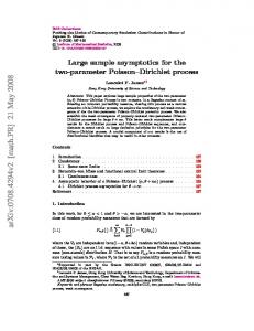
In our analysis, we focus on the Binary Erasure Channel. Erasures in communication systems can arise in different layers. At the physical layer, if the received signal falls outside acceptable bounds, it is declared as an erasure. At the data link layer, some packets may be dropped because of checksum errors. At the network layer, packets that traverse through the network may be dropped because of buffer overflow at intermediate nodes and therefore never reach the destination. All these errors can result in erasures in the received bit stream. In order to investigate how different coding techniques would affect the delay distribution, we use a general coding framework called incremental redundancy codes. In this framework, each codeword is split into several pieces with equal size, which are called codeword trunks. The sender sends only one codeword trunk at a time. If the receiver cannot decode the information, it will request the sender to send another piece of the codeword trunk. Therefore, at every transmission, the receiver gains extra information, which is called incremental redundancy. In order to combat channel erasures, we use erasure codes as channel coding to encode the information. Erasure codes represent a group of coding schemes which ensure that even when some portions of the codeword are lost, it is still possible for the receiver to recover the corresponding information. Roughly speaking, the encoder transforms a data packet of l symbols into a longer codeword of lc symbols, where the ratio β = l/lc is called the code-rate. An erasure code is said to be near optimal if it requires slightly more than l symbols, say (1 + ε)l symbols, to recover the information, where ε can be made arbitrary small at the cost of increased encoding and decoding complexity. Many elegant low complexity erasure codes have been designed for erasure channels, e.g., Tornado Code [7], LT code [8], and Raptor code [9]. For the sake of simplicity, throughout the paper, we assume ε = 0. In other words, any β fraction of the codeword can recover the corresponding information and a lower β indicates a larger redundancy in the codeword. We specify different scenarios in this paper. In the first scenario, as shown in Fig. 1, the entire codeword
βLc
with infinite support and codeword length with finite support, respectively. For the former, the codeword length distribution has an exponentially decaying tail with decay rate λ, for the latter, the codeword length has an upper bound b.
Data packet Encoder Lc
Erasure Channel
Codeword unit
Received bit Erased bit
Fig. 1.
No Resend
Received bits >βLc Yes Decode
Decoder that does not use memory scenario
is transmitted as a unit, and received bits are simply discarded if the corresponding information cannot be recovered. Note that in this scenario, the decoder memory is not exploited for caching received bits across different transmissions. This scenario occurs because the receiver may not have the requisite computation/storage power to keep track of all the erasure positions and the bits that have been previously received, especially when the receiver is responsible for handling a large number of flows simultaneously. In the second scenario, we assume that the receiver has enough memory space and computational power to accumulate received bits from different (re)transmissions, which enables the use of incremental redundancy codes, where a codeword of length lc is split into r codeword trunks with equal size, and these codeword trunks are transmitted one at a time. At the receiver, all successfully received bits from every transmission are buffered at the receiver memory according to their positions in the codeword. If the receiver cannot decode the corresponding information, it will request the sender to send another piece of codeword trunk. At the sender, these codeword trunks are transmitted in a roundrobin manner. We call these two scenarios Decoder that does not use memory and Decoder that uses momery, respectively. Given the above two different types of decoder, there are two more factors that can affect the distribution of delay. (I) Channel Dynamics: In order to capture the time correlation nature of the wireless channels, we assume that the channel is Markovian modulated. More specifically, we assume a time slotted system where one bit can be transmitted per time slot, and the current channel state distribution depends on channel states in the previous k time slots. When k = 0, it corresponds to the i.i.d. channel model. (II) Codeword length distribution: We assume throughout the paper that the codeword length is light tail distributed, which implies that the system works in a benign environment. We consider two different codeword length distributions, namely, codeword length
Contribution The main contribution of this work is the following: • When decoder memory is not exploited, the tail of the delay distribution depends on the code rate. Specifically, we show that when the coding rate is above a certain threshold, the delay distribution is heavy tailed, otherwise it is light tailed. This shows that substantial gains in delay can be achieved over the standard retransmission case (repetition coding) by adding a certain amount of redundancy in the codeword. As mentioned earlier, prior work has shown that repetition coding results in heavy tailed delays even when the packet size are light tailed. • When decoder memory is exploited, the tail of the delay distribution is always light-tailed. This implies that the use of receiver memory results in a further substantial reduction in the transmission delay. • The aforementioned results are for the case when the codeword size can have infinite support. We also characterize the transmission delay for each of the above cases when the codeword size has finite support (zero-tailed), and show similar tradeoffs between the coding rate and use of receiver memory in terms of the main body of the delay distribution (rather than the eventual tail). The remainder of this paper is structured as follows: In Section II, we describe the system model. In Section III we consider the scenario where the decoder memory is exploited. Then, in Section IV we investigate the situation where the decoder does not use memory. Finally, in Section V, we provide numerical studies to verify our main results. II. S YSTEM M ODEL The channel dynamics are modeled as a slotted system where one bit can be transmitted per slot. Furthermore, we assume that the slotted channel is characterized by a binary stochastic process {Xn }n≥1 , where Xn = 1 corresponds to the situation when the bit transmitted at time slot n is successfully received, and Xn = 0 when the bit is erasured (called an erasure). Since, in practice, the channel dynamics are often temporarily correlated, we investigate the situation in which the current channel state distribution depends on the channel states in the preceding k time slots. More precisely, for Fn = {Xi }i≤n and fixed k, we define Hn = {Xn , . . . , Xn−k+1 } for n ≥ k ≥ 1 with Hn = {∅, Ω} for k = 0, and assume that P[Xn = 1|Fn−1 ] = P[Xn = 1|Hn−1 ] for all n ≥ k. To put it another way, the augmented state Yn , [Xn , . . . , Xn−k ], n ≥ k forms a Markov
chain. Let Π denote the transition matrix of the Markov chain {Yn }n≥k+1 , where Π = [π(s, u)]s,u∈{0,1}k , with π(s, u) being the one-step transition probability from state s to state u. Throughout this paper, we assume that Π is irreducible and aperiodic, which ensures that this Markov chain is ergodic [10]. Therefore, for any initial value Hk , the parameter γ is well defined and given by
(r)
(r)
The transmission delay is defined as Tm = Nm Lc /r. Definition 2 (Decoder that does not use memory). The total number of transmissions for a codeword with variable length Lc when the decoder does not use memory is defined as ( ) Lc X Nf , inf n : X(n−1)Lc +i > βLc . i=1
The transmission delay is defined as Tf = Nf Lc .
γ = lim P[Xn = 1], n→∞
and, from ergodic theorem (see Theorem 1.10.2 in [10]) Pn � � k=1 Xi = γ = 1, P lim n→∞ n
For a codeword with variable length Lc (b), the corresponding numbers of transmissions and delays are de(r) (r) noted as Nm (b), Tm (b), Nf (b), and Tf (b), respectively.
which means the long-term fraction of the bits that can be successfully received is equal to γ. Therefore, we call γ the channel capacity. In the degenerated case when k = 0, we have a memoryless binary erasure channel (i.i.d. binary erasure channel). Correspondingly, Hn = {∅, Ω} and Π = [γ]. As mentioned in the introduction, we study two different scenarios in this paper, namely decoder that uses memory and decoder that does not use memory. In the first scenario, the sender splits a codeword into r codeword trunks with equal size and transmits them one at a time in a round-robin manner, while the receiver uses memory to cache all previously successfully received bits according to their positions in the codeword. In the second scenario, the receiver discards any successfully received bits if they cannot recover the corresponding information, and the sender transmits the entire codeword as a unit. We let Lc denote the number of bits in the codeword with infinite support, and assume that there exist λ > 0 and z > 0 such that log P[x < Lc < x + z] lim = −λ. (1) x→∞ x We let Lc (b) denote the number of bits in the codeword with finite support, with b being the maximum codeword length, and let P[Lc (b) > x] = P[Lc > x|Lc < b] for any x > 0. We focus on erasure codes, where a fixed fraction (0 < β < 1) of bits in the codeword can lead to a successful decoding. We call this fraction β code-rate. Formal definitions of the number of retransmissions and the delays are given as follows:
Notations
Definition 1 (Decoder that uses memory). The total number of transmissions for a codeword with variable length Lc and number of codeword trunks r when the decoder uses memory is defined as ( (Lc/r)l r X X (r) Nm , inf n : l=1 i=(Lc /r)(l−1)+1
b(n−l)/rc+1
1
X j=1
X(j−1)Lc +i ≥ 1 > βLc
.
In order to present the main results, we introduce some necessary notations here. Notation 1. Let ρ(M ) denote the Perron-Frobenius eigenvalue (see Theorem 3.11 in [11]) of the matrix M , which is the largest eigenvalue of M . Notation 2. For k ≥ 1, let {si }1≤i≤2k = {0, 1}k denote the state space of {Yn }n≥k+1 , where si = [si1 , si2 , . . . , sik ] and sij ∈ {0, 1} ∀i, j. Then, we define a mapping f from {si }1≤i≤2k to {0, 1} as f (si ) = 1 − sik . Notation 3. Let Λn (β, Π) denote the large deviation rate function, which is given by Λn (β, Π) = sup {θ(1 − β) − log ρn (θ, Π)} , θ 1
where
( ρn (θ, Π) =
� � ⊗n ρ eθD Π⊗n (1 − γ)n + (1 − (1 − γ)n ) eθ
k≥1 , k=0
D = diag [f (s1 ), f (s2 ), . . . , f (s2k )] for k ≥ 1. Notation 4. Let µn denote the root of the rate function Λn (β, Π). More precisely, Λn (µn , Π) = 0. Notation 5. α = inf {n : µn ≥ β} λ + Λn (β, Π)1(n ≥ α) Λo1 = inf n∈N n+1 λ + Λ n+1 (β, Π)1(n ≥ α − 1) Λo2 = inf n∈N n+1 � λ if β >γ Λo3 = . λr if β ≤ γ drβ/γe 1 For a matrix A, A⊗n is the n-fold Kronecker product of A with itself, or we can call it the nth Kronecker power of A.
III. D ECODER THAT USES M EMORY When the decoder uses memory to cache all previously successfully received bits, we can apply incremental redundancy codes, where the sender splits a codeword into r codeword trunks and transmits one codeword trunk at a time. If the receiver, after receiving a codeword trunk, is not able to decode the corresponding information, it will use memory to cache the successfully received bits in the codeword trunk and request the sender to send another codeword trunk. In this way, at every transmission, the receiver gains extra information, which we call incremental redundancy. The sender will send these codeword trunks in a round-robin manner, meaning that if all of the codeword trunks have been requested, it will start over again with the first codeword trunk. It should be noted that incremental redundancy code is a fairly general framework in that if r = 1, it degenerates to a fixed rate erasure code, while as r approaches infinity, it resembles a rateless erasure code. A. Codeword with infinite support When the distribution of codeword length Lc has an exponentially decaying tail with decay rate λ, as indicated by Equation (1), we find that the delay will always be light-tailed, and we characterize the decay rate in Theorem 1. Theorem 1. In the case when the decoder uses memory, when we apply incremental redundancy code with parameter r to transmit codeword with variable length Lc , we obtain a lower and upper bound on the decay rate of delay, i h (r) log P Tm > t ≤ min{Λo2 , Λo3 }, − lim inf t→∞ i ht (r) log P Tm > t − lim sup ≥ min{Λo1 , Λo3 }. t t→∞ In the special case when r = 1, h i (1) log P Tm > t − lim = min{Λo1 , λ}. n→∞ t The definitions of Λo1 , Λo2 and Λo3 can be found in Notation 5. Proof: see Section VI-B. Remark 1.1. From the definitions of Λo1 , Λo2 and Λo3 in Notation 5 we observe that firstly, the decay rate of delay when r = 1 is no greater than the decay rate of delay when r > 1 (min{Λo1 , λ} ≤ min{Λo1 , Λo3 }), which means that incremental redundancy code (r > 1) outperforms fixed rate erasure code (r = 1); secondly, the decay rate of delay increases with the increase of r, which means we can reduce delay by increasing the number of codeword trunks r. These observations are verified through Example 1 in Section V.
B. Codeword with finite support In practice, codeword length is bounded by the maximum transmission unit (MTU). Therefore, we investigate the case when the codeword has variable length Lc (b), with b being the maximum codeword length, and characterize the corresponding delay distribution in Theorem 2. Theorem 2. In the case when decoder uses memory, when we apply incremental redundancy code with parameter r to transmit codeword with variable length Lc (b), we get 1) for any η > 0 and any b0 > 0, we can find b(η) > 0 such that for any b > b(η), we have ∀t ∈ [no2 (b − b0 ), no2 b], h i (r) log P Tm (b) > t ≤ (1 + η)Λb2 . (1 − η)Λb1 ≤ − t 2) in the special case when r = 1, for any η > 0 and any b0 > 0, we can find b(η) > 0 such that for any b > b(η), we have ∀t ∈ [no1 (b − b0 ), no1 b], i h (1) log P Tm (b) > t (1 − η)Λb ≤ − ≤ (1 + η)Λb , t where no1 = arg inf (λ + Λn (β, Π)1(n ≥ α))/(n + 1), n∈N
no2 Λb1 Λb2 b
= arg inf (λ + Λn+1 (β, Π)1(n ≥ α − 1))/(n + 1), n∈N
= =
Λ =
Λo1 Λo2 Λo1
+ min{0, Λo3 − Λo1 }1(no2 = 1), + min{0, Λo3 − Λo2 }1(no2 = 1), + min{0, λ − Λo1 }1(no1 = 1).
Proof: see Section VI-C. Remark 2.1. This theorem shows that even if the codeword length has an upper bound b, the distribution of delay still has a light-tailed main body whose decay rate is similar as the decay rate of the infinite support scenario. The waist of this main body is no2 b when r > 1 and no1 b when r = 1. Since both no2 and no1 are independent of b, we know that the waist of this light-tailed main body scales linearly with respect to the maximum codeword length b. This theorem is verified through Example 2 in Section V. IV. D ECODER THAT DOES NOT USE M EMORY For receivers that do not have the required computation/storage power, it is difficult to keep track of all the erasure positions and the bits that have been successfully received. Therefore, in this section, we study the case when the decoder does not use memory, as illustrated in Fig. 1. In this situation, since the receiver simply discards any successfully received bits if they cannot recover the corresponding information, it is better for the sender to transmit the whole codeword as a unit instead of dividing the codeword into pieces before transmission.
Proof: see Section VI-E.
A. Codeword with infinite support Interestingly, we observe an intriguing threshold phenomenon. We show that when the codeword length distribution is light-tailed and has an infinite support, the transmission delay is light-tailed (exponential) only if γ > β, and heavy-tailed (power law) if γ < β. Theorem 3 (Threshold phenomenon). In the case when decoder does not use memory and the codeword has variable length Lc , we get 1) if β > γ, then lim
n→∞
log P [Nf > n] . log n λ log P [Tf > t] = lim =− . t→∞ log t Λ1 (β, Π)
From Theorem 4 we know that even if the codeword length is bounded, the heavy-tailed main body could still play a dominant role. From Theorem 3 we know that when λ < Λ1 (β, Π) and β > γ, the throughput will vanish to zero as b approaches infinity. Now we explore how fast the throughput vanishes to zero as b increases. Let {Li }i≥1 be the i.i.d. sequence of codeword lengths with distribution Lc (b). Denote Ti as the transmission delay of Li . ThePthroughput Pnof this system is defined as n ∆(b) = limn→∞ i=1 βLi / i=1 Ti .
2) if β < γ, then log P [Tf > t] = − min {λ, Λ1 (β, Π)} . t The definition of Λ1 (β, Π) can be found in Notation 3. lim
t→∞
Proof: see Section VI-D. Remark 3.1. The tail distribution of the transmission delay changes from power law to exponential, depending on the relationship between code-rate β and channel capacity γ. If λ/Λ1 (β, Π) < 1, the system even has a zero throughput. Under the heavy-tailed delay case when β > γ, we can further show that if the codeword length is upper bounded, the delay distribution still has a heavy-tailed main body, although it eventually becomes light-tailed. Theorem 4. In the case when decoder does not use memory and the codeword has variable length Lc (b), if β > γ, for any η > 0, we can find n(η) > 0 and b(η) > 0 such that 1) For any b > b(η), we have ∀n ∈ [n(η), nb ], log P [Nf (b) > n] Λ1 (β, Π) 1−η ≤− ≤ 1 + η. log n λ 2) log P [Nf (b) > n] = log (P [Nf > 1|Lc = b]) . lim n→∞ n 3) For any b > b(η), we have ∀t ∈ [n(η)b, nb b], log P [Tf (b) > t] Λ1 (β, Π) ≤ 1 + η. log t λ
4) lim
n→∞
Theorem 5 (Throughput). In the case when decoder does not use memory and the codeword has variable length Lc (b), if β > γ and λ < Λ1 (β, Π), we have − lim sup b→∞
log ∆(b) ≥ Λ1 (β, Π) − λ. b
The definition of Λ1 (β, Π) can be found in Notation 3.
B. Codeword with finite support
1−η ≤−
Remark 4.1. From Equation (2) and by Lemma 3, we can obtain log nb lim = Λ1 (β, Π), (3) b→∞ b which implies that nb increases exponentially fast with the increase of maximum codeword length b. Since the waist of the heavy-tailed main body of the delay distribution is nb b, we know that the waist also scales exponentially fast as we increase the maximum codeword length b.
log P [Tf (b) > t] 1 = log (P [Tf > 1|Lc = b]) , t b
where −1
nb = (P[Nf = 1|Lc = b])
.
The definition of Λ1 (β, Π) can be found in Notation 3.
(2)
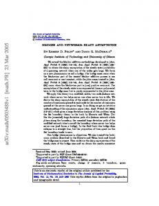
Proof: see Section VI-F. Remark 5.1. Theorem 5 indicates that when code-rate β is greater than channel capacity γ and λ < Λ1 (β, Π), as the maximum codeword length b increases, the throughput vanishes to 0 at least exponentially fast with rate Λ1 (β, Π) − λ. V. S IMULATIONS In this section, we conduct simulations to verify our main results. As is evident from the following figures, the simulations match theoretical results well. Example 1. In this example, we study the case when the decoder uses memory and the codeword length has infinite support. We assume that the channel is i.i.d.(k = 0). As shown in Theorem 1, under the above assumptions, the delay distribution is always light-tailed. In order to verify this result, we assume that Lc is geometrically distributed with mean 100 (λ = 0.01), and choose coderate β = 0.5 and channel capacity γ = 0.25. By Theorem 1 we know that when r = 1, the decay rate of delay is min{Λo1 , λ} = 0.0025; when r = 3, the decay rate of delay is min{Λo1 , Λo3 } = min{Λo2 , Λo3 } = 0.0037; when r = 5, the decay rate of delay is min{Λo1 , Λo3 } = min{Λo2 , Λo3 } = 0.0042. From Fig. 2 we can see that the decay rate of delay increases when r increases from 1 to 5, and the theoretical result is quite accurate.
a=0.5,`=0.25,h=0.01
0
0
10
10 r=1 Simulation r=3 Simulation r=5 Simulation r=1 Asymptotic r=3 Asymptotic r=5 Asymptotic
ï1
ï1
10
P[T(r) >t] m
P[T(1) (b)>t] m
10
`=0.75,a=0.1 b=' `=0.75,a=0.1
ï2
ï2
10
ï3
10
10
b=200 b='
b=400 b=600
ï4
10
b=800
ï3
500
Fig. 2.
1000
1500 2000 delay t(slots)
2500
3000
0
5000
Illustration for Example 1
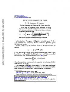
Example 2. In this simulation, we study the case when the decoder uses memory and the codeword length has a finite support. We assume that the channel is i.i.d. (k = 0), code-rate β = 0.75, λ = 0.01, r = 1, and channel capacity γ = 0.1. From these system parameters we can calculate no1 = 14 and Λb = min{Λo1 , λ} = 7.1429 × 10⁻⁴ . We choose four sets of maximum codeword length b as 200, 400, 600, 800. Theorem 2 indicates that the delay distribution has a light-tailed main body with decay rate Λb = 7.1429 × 10⁻⁴ and waist nb b = 14 × b. In Fig. 3 we plot the delay distributions when b = 200, 400, 600, 800 together with the infinite support case when b = ∞, and we use a short solid line to indicate the waist of the light-tailed main body. As we can see from Fig. 3, the theoretical waists of the main bodies, which are nb b = 14 × b = 2800, 5600, 8400, 11200, are close to the simulation results. Example 3. Now we use simulations to verify Theorem 4. Theorem 4 says that when the decoder does not use memory, if code rate β is greater than channel capacity γ and the codeword length has a finite support, the distribution of delay as well as the distribution of number of retransmissions have a heavy-tailed main body and an exponential tail. The waist of the main body increases exponentially fast with the increase of maximum codeword length b. In this experiment, we set code-rate β = 0.25, channel capacity γ = 0.20, k = 0, and λ = 0.01. From these parameters we can get Λ1 (β, Π) = 0.0074. We choose four sets of maximum codeword length b as 200, 400, 600, 800. As Equation (3) indicates, the waist of the heavy-tailed main bodies of the number of retransmissions is nb ≈ ebΛ1 (β,Π) = 4.3772, 19.1595, 83.8641, 367.0865. In Fig. 4, we plot the distribution of the number of retransmissions when b = 200, 400, 600, 800 together with the infinite support case when b = ∞, and we use a short solid line
Fig. 3.
10000 Delay t(slots)
15000
Illustration for Example 2
to indicate the waist of the heavy-tailed main body. As can be seen from Fig. 4, the simulation matches with our theoretical result. 0
10
`=0.25,a=0.20,b=' `=0.25,a=0.20 ï1
10
f
0
Pr[N (b)>n]
10
ï2
10
b='
ï3
10
b=200
b=400 b=600
ï4
10
0
10
1
2
3
10 10 10 Number of retransmissions: n Fig. 4.
b=800 4
10
Illustration for Example 3
VI. P ROOFS A. Lemmas In order to prove the theorems, first we need the following three lemmas. Lemma 1. (1) P[Nm > n|Lc = lc ] = e−lc Λn (β,Π)1(n≥α)+gn (lc ) ,
where � gn (lc ) ∈
o(lc ) o(1)
if n ≥ α . otherwise
Proof: First we consider the case when k ≥ 1. By Definition 1, we have � (1) � P Nm > n|Lc = lc # ! " L n c X X 1 X(j−1)Lc +i ≥ 1 ≤ βLc Lc =P i=1 j=1 # " L ! n c X X =P 1 X(j−1)Lc +i = 0 > (1 − β)Lc Lc i=1 j=1 " " L n � � c Y X =E P 1 X(j−1)Lc +i = 0
i=1+k
≥ e− inf 1−ω>1−β Λn (β,Π)(1+ε)lc , # " L c X fn (Yin ) > (1 − β)Lc − k Lc = lc P
(6)
≤ e− inf 1−ω>1−β Λn (β,Π)(1−ε)lc ,
(7)
i=1+k
i=1 j=1
# # n [ > (1 − β)Lc Lc , Ej Lc ,
find lε such that # " L c X P fn (Yin ) > (1 − β)Lc Lc = lc
(4)
whenever lc > lε . Since Λn (ω, Π) is a large deviation rate function, from [11] we know that � Λn (β, Π) if µn < β inf Λn (ω, Π) = 0 otherwise 1−ω>1−β = Λn (β, Π)1(n ≥ α).
j=1
� where Ej , � X(j−1)Lc +1 , . . . , X(j−1)L � c +k , 1 ≤ j ≤ n. Let Yin = Yi , YLc +i , . . . , Y(n−1)Lc +i and fn (Yin ) =
n Y
The upper and lower bounds (7) and (6), together with Equation (4), (5) and (8), imply that log P [Nm > n|Lc = lc ] lc →∞ lc ≤ (1 + ε)Λn (β, Π)1(n ≥ α), log P [Nm > n|Lc = lc ] − lim sup lc lc →∞ − lim inf
�
f Y(j−1)Lc +i .
j=1
Sn If Lc > k, then given j=1 Ej , {Yin }k k, we have the following relationship ) � � Lc Y n X 1 X(j−1)Lc +i = 0 > (1 − β)Lc
(
i=1+k j=1
( ⊆
) � � Lc Y n X 1 X(j−1)Lc +i = 0 > (1 − β)Lc i=1 j=1
( ⊆
) � � Lc Y n X 1 X(j−1)Lc +i = 0 > (1 − β)Lc − k .
≥ (1 − ε)Λn (β, Π)1(n ≥ α), which, with ε → 0, completes the proof when k ≥ 1. Next, let us consider the case when k = 0. In this memoryless channel case, for a single bit in the codeword, after nth transmission, the probability that this bit is successfully received is 1 − (1 − γ)n . Therefore equivalently, we can consider a single transmission in a memoryless channel with erasure probability (1 − γ)n . Then, by a direct application of G¨ artner-Ellis theorem (Theorem 2.3.6 in [11]), we have, for any n ≥ 1, lim
i=1+k j=1
lc →∞
Using the above observation, we can construct upper and lower bounds as follows. " L n ! # n c Y X [ P 1 X(j−1)Lc +i = 0 > (1 − β)Lc Lc , Ej i=1 j=1 j=1 " L # n c X [ ≥P fn (Yin ) > (1 − β)Lc Lc , Ej , j=1 i=1+k " L n ! # n c Y X [ P 1 X(j−1)Lc +i = 0 > (1 − β)Lc Lc , Ej i=1 j=1 j=1 " L # n c X [ ≤P fn (Yin ) > (1 − β)Lc − k Lc , Ej . (5) i=1+k
(8)
j=1
By a direct application of Theorem 3.1.2 inS[11], we know n that for a given ε > 0 and any values of j=1 Ej , we can
log P[Nm > n|Lc = lc ] = −Λn (β, Π)1 (n ≥ α) , lc
where � � �� Λn (β, Π) = sup θ(1 − β) − log E Xi eθXi θ
� = sup{θ(1 − β) − log 1 − (1 − γ)n + (1 − γ)n eθ } θ
β 1−β + (1 − β) log , n 1 − (1 − γ) (1 − γ)n m l and α = log(1−β) log(1−γ) . = β log
Lemma 2. Assume b is a function of t, which satisfies b , b(t) > yt . Then, for any x, y ∈ N we have h i (1) t log P Nm > x, y+1 < Lc (b) < yt lim t→∞ t λ + Λx (β, Π)1(x ≥ α) . =− y+1
Proof: � (1) P Nm > x, bt/yc
=
X lc =dt/(y+1)e
�
t t < Lc (b) < y+1 y � � (1) P Nm > x Lc (b) = lc P [Lc (b) = lc ]
� � �� � � t t t (1) ≤P Nm > x Lc (b) = P < Lc (b) < . y+1 y+1 y (9) From Lemma 1 we know that � � (1) P Nm > x Lc (b) =
channel states. Observe that if Lc > k, for any 1 ≤ j ≤ n, jLc X Xi ≤ βLc i=(j−1)Lc +1+k jLc X ⊆ Xi ≤ βLc i=(j−1)Lc +1 jLc X ⊆ Xi ≤ βLc − k , i=(j−1)Lc +1+k
t y+1
��
=e−d y+1 eΛx (β,Π)1(x≥α)+gx (lc ) . t
(10)
Since b = b(t) > yt , by the definition of Lc (b), we can easily obtain h i t log P y+1 < Lc (b) < yt λ lim =− . (11) t→∞ t y+1 Combining Equation (11), (10) and (9), we get h i (1) t log P Nm > x, y+1 < Lc (b) < yt lim sup t t→∞ ≤ − (λ + Λx (β, Π)1(x ≥ α))/(y + 1). The lower bound can be constructed in a similar manner. Lemma 3.
1) if β > γ, then � �n P [Nf > n|Lc = lc ] = 1 − e−lc Λ1 (β,Π)(1+g(lc )) ,
where g(lc ) ∈ o(1) as lc → ∞. 2) if β < γ, then P [Nf > n|Lc = lc ] = e−nlc Λ1 (β,Π)(1+s(lc )) , where s(lc ) ∈ o(1) as lc → ∞. Proof: From Definition 2 we know
which further yields jLc X P
n [ Xi ≤ βLc − k Ei , Lc i=1 i=(j−1)Lc +1+k jL n [ Xc Ei , Lc Xi ≤ βLc ≥P i=1 i=(j−1)Lc +1 n jL c [ X ≥P Xi ≤ βLc Ei , Lc . i=(j−1)Lc +1+k
i=1
Similarly as the proof of Lemma 1, by Theorem 3.1.2 in [11], we obtain, for any 1 ≤ j ≤ n i hP Sn jLc log P i=1 Ei , Lc = lc i=(j−1)Lc +1 Xi > βLc lim lc →∞ lc = −Λ1 (β, Π)1(β > γ), hP i Sn jLc log P i=1 Ei , Lc = lc i=(j−1)Lc +1 Xi ≤ βLc lim lc →∞ lc = −Λ1 (β, Π)1(β < γ), which, by combining Equation 12, completes the proof. B. Proof of Theorem 1
proof of Theorem 1: Observe that h i (r) P Tm >t � � ∞ h i X tr tr (r) (r) = P Tm > t, < Lc ≤ + P Tm > t, Lc > t h+1 h h=r � � ∞ (n+1)r−1 X X tr tr (r) = P Nm > h, < Lc ≤ h+1 h n=1 h=nr h i (r) + P Tm > t, Lc > t . (13)
P[Nf > n|Lc ] jLc \ X =P Xi ≤ βLc Lc . 1≤j≤n i=(j−1)Lc +1 jLc n [ \ X focus on the first part of Equation (13). Denote =E P Xi ≤ βLc Ej , Lc Lc Let us first i P(n+1)r−1 h (r) tr Pntr = h=nr P Nm > h, h+1 < Lc ≤ tr , then it is j=1 1≤j≤n i=(j−1)Lc +1 h easy to check that jLc n n [ Y X � � =E P Xi ≤ βLc Ei , Lc Lc , (12) t t (1) P ≤ P N > n, < L ≤ , ntr c m i=1 j=1 i=(j−1)Lc +1 n+1 n � � � t t (1) where Ej , X(j−1)Lc +1 , . . . , X(j−1)Lc +k , 1 ≤ j ≤ n. Pntr ≥ P Nm > n + 1, < Lc ≤ , n+1 n The last equation is due to the Markov property of the
which, by Lemma 2, yield log Pntr λ + Λn (β, Π)1(n ≥ α) ≤− , t n+1 log Pntr λ + Λn+1 (β, Π)1(n ≥ α − 1) lim inf ≥− . (14) t→∞ t n+1
lim sup t→∞
For the second part of Equation (13), we have, by the definition of Lc , h i (r) log P Tm > t, Lc > t − lim t ( t→∞ c >t] limt→∞ log P[L if β > γ t = log P[Lc >tr/d rβ γ e] if β ≤ γ limt→∞ t � λ if β > γ = = Λo3 . (15) λr if β ≤ γ drβ/γe Combining Equation (13), (14) and (15), we get i h (r) log P Tm > t lim sup t t→∞ P∞ n log n=1 Pntr , = max lim sup t t→∞ i) h (r) log P Tm > t, Lc > t lim t→∞ t � � (a) λ + Λn (β, Π)1(n ≥ α) ≤ max − inf , −Λo3 n n+1 = − min{Λo1 , Λo3 }.
lim
where the definition of no1 can be found in Notation 5. D. Proof of Theorem 3
(16)
log Pntr λ + Λn (β, Π)1(n ≥ α) =− , t h ni + 1 (1)
lim
log P Tm > t, Lc > t
t→∞
t
= −λ,
+ b0 . In other whenever t > t(η). We denote b(η) , t(η) no 2 words, for any b > b(η), whenever t ∈ [(b − b0 )no2 , bno2 ], h i (r) log P Tm > t, not+1 < Lc (b) ≤ nto 2 2 − ≤ (1 + η)Λo2 , t i h (r) log P Tm > t, not+1 < Lc (b) ≤ nto 2 2 − ≥ (1 − η)Λo1 , t which, by using the same technique as in Equation (16), completes the proof of the first part. The second part of Theorem 2 follows by noting that � � i h (1) log P Tm > t, not+1 < Lc nto + b0 ≤ nto 1 1 1 = Λo1 , lim − t→∞ t
The lower bound can be found in a similar manner. Notice that inequality (a) in the preceding equation is true because Pntr is nonzero only for a finite number of n, which is due to the fact that Lc cannot be less than 1. In the special case when r = 1, by Lemma 2 and the definition of Lc , we have t→∞
Then, for any η > 0 and for any b0 > 0, we can find t(η) such that h � � i (r) log P Tm > t, not+1 < Lc nto + b0 ≤ nto 2 2 2 − ≤ (1 + η)Λo2 , t i h � � (r) log P Tm > t, not+1 < Lc nto + b0 ≤ nto 2 2 2 ≥ (1 − η)Λo1 , − t
(17)
which, by combining Equation (13), completes the proof.
C. Proof of Theorem 2 proof of Theorem 2: From the definition of no2 , Λo1 and Λo2 in Notation 5 and by Lemma 2, we can obtain, for any b0 > 0, h � � i (r) log P Tm > t, not+1 < Lc nto + b0 ≤ nto 2 2 2 lim sup − ≤ Λo2 , t t→∞ h � � i (r) log P Tm > t, not+1 < Lc nto + b0 ≤ nto 2 2 2 lim inf − ≥ Λo1 . t→∞ t
proof of Theorem 3: 1) If β > γ, by Lemma 3, for any ε > 0, we can find lε such that � �n P[Nf > n|Lc = lc ] ≥ 1 − e−lc Λ1 (β,Π)(1−ε) , whenever lc > lε . Then we have, for n large enough, P[Nf > n] = E [P[Nf > n|Lc ]] h � �n i ≥ E Lc > l� , 1 − e−Λ1 (β,Π)(1−�)Lc h log n log n < Lc < + z, ≥E Λ1 (β, Π)(1 − �) Λ1 (β, Π)(1 − �) � �n i 1 − e−Λ1 (β,Π)(1−�)Lc h log n log n < Lc < + z, ≥E Λ (β, Π)(1 − �) Λ1 (β, Π)(1 − �) �1 �n i 1 − e−(log n) � �n log n −λ(1+�) Λ (β,Π)(1−�) 1 ≥e 1 − e−(log n) . Taking logarithms on both sides of the preceding inequality, we get lim inf n→∞
log P[Nf > n] λ(1 + �) ≥− , log n Λ1 (β, Π)(1 − �)
which, when � → 0, results in the lower bound. Next, we prove the upper bound. Using the same technique as in the proof of the lower bound, and by the definition of Lc , we can find lε such that
E. Proof of Theorem 4 h
�
P[Nf > n] ≤ P Lc > l� , 1 − e−Λ1 (β,Π)(1+�)Lc
�n i
+ P[Nf > n, Lc ≤ l� ] ∞ � �n X ≤ 1 − e−Λ1 (β,Π)(1+�)l P[Lc = l] + O(e−ξn ), l=l�
�Z ≤O
� ∞� �n −Λ1 (β,Π)(1+�)x −λ(1−�)x 1−e e dx
0 −ξn
+ O(e
proof of Theorem 4: 1) By Lemma 3 we know that when β > γ � �n P [Nf > n|Lc = lc ] = 1 − e−lc Λ1 (β,Π)(1+g(lc )) , with g(lc ) ∈ o(1) as lc → ∞. Let us denote ln as the root n of the function lc (1 + g(lc )) − Λ1log (β,Π) . In other words, ln (1 + g(ln )) =
).
log n . Λ1 (β, Π)
For any b0 > 0, we have Computing the integrated in the preceding inequality, we obtain log P[Nf > n] λ(1 − �) lim sup ≤− , log n Λ1 (β, Π)(1 + �) n→∞
P [Nf > n, ln − z < Lc (ln + b0 ) ≤ ln ] ≥P [Nf > n|Lc = ln ] P [ln − z < Lc (ln + b0 ) ≤ ln ] . (19) Note that, by Lemma 3, log P [Nf > n|Lc = ln ] n→∞ log n �n log 1 − e−ln Λ1 (β,Π)(1+g(lc )) = lim n→∞ log n n log(1 + n1 ) = lim = 0. n→∞ log n lim
which, with � → 0, proves the upper bound. Now, we prove the result for P[Tf > t]. The upper bound follows by noting that P[Tf > t] ≤ P[Nf Lc > t, Lc ≤ h log t] + P[Lc > h log t] ≤ P[Nf > t/(h log t)] + P[Lc > h log t],
(20)
Also, by the definition of Lc (b), where limt→∞ log P[Nf > t/(h log t)]/ log t = λ/Λ1 (β, Π), and P[Lc > h log t] = o (P[Nf > t/(h log t)]) for h large enough. The lower bound follows by noting that, for some l2 > l1 > 0 with P[l1 < Lc < l2 ] > 0, P[Tf > t] ≥ P[Nf Lc > t, l1 < Lc < l2 ]
(21)
Combining Equation (19), (20) and (21), we get
≥ P[Nf > t/l1 ]P[l1 < Lc < l2 ].
log P [Nf > n, ln − z < Lc (ln + b0 ) ≤ ln ] log n λ =− . Λ1 (β, Π) lim
2) Observe that
n→∞
P[Tf > t] =P[Lc > t] +
log P [ln − z < Lc (ln + b0 ) ≤ ln ] log n log P [ln − z < Lc (ln + b0 ) ≤ ln ] ln = lim n→∞ ln log n 1 =−λ . Λ1 (β, Π) lim
n→∞
� ∞ X P Nf > n, n=1
� t t < Lc ≤ . n+1 n
(18)
Using the same technique as in the proof of Lemma 2 and by Lemma 3, we have, when β < γ, i h t < Lc ≤ nt log P Nf > n, n+1 nΛ1 (β, Π) + λ =− , lim t→∞ t n+1 log P[Lc > t] lim = −λ, t→∞ t which, by combining Equation 18 and using the same technique as in Equation (16), yield � � � � log P[Tf > t] nΛ1 (β, Π) + λ lim = − min inf ,λ t→∞ n∈N t n+1 = − min{Λ1 (β, Π), λ}.
Therefore, for any η > 0, we can find a n1 (η) such that log P [Nf > n, ln − z < Lc (ln + b0 ) ≤ ln ] n→∞ log n λ (1 + η), (22) ≥− Λ1 (β, Π) lim
whenever n > n1 (η). Also, by Theorem 3, we can find n2 (η) such that lim
n→∞
log P [Nf > n] λ ≤− (1 − η). log n Λ1 (β, Π)
(23)
Let n(η) , max{n1 (α), n2 (α)} and b(η) , ln(η) + b0 . By combining Equation (22) and (23), we know that for any η > 0, we can find b(η) such that for any b > b(η), lim sup n→∞
log P [Nf (b) > n] log P [Nf > n] ≤ lim n→∞ log n log n λ ≤− (1 − η), Λ1 (β, Π)
and log P [Nf (b) > n] lim inf n→∞ log n log P [Nf > n, ln − z < Lc (ln + b0 ) ≤ ln ] ≥ lim n→∞ log n λ ≥− (1 + η), Λ1 (β, Π) whenever n ∈ [n(η), nb ], where nb satisfies b(1 + g(b)) = log nb Λ1 (β,Π) . From Lemma 3, we know that −1
nb = eΛ1 (β,Π)b(1+g(b)) = (P [Nf = 1|Lc = b])
.
(24)
2) Note that log P [Nf (b) > n] n � � log (P [Lc (b) = lc , Nf (b) > n]) = max lim n→∞ lc n � log (P [Lc (b) = lc ]) , = max lim n→∞ lc n � log (P [Nf (b) > 1|Lc (b) = lc ]) lim
n→∞
= log (P [Nf (b) > 1|Lc (b) = b]) . 3,4) The proof of 3) and 4) follows by noting that Tf (b) = Nf (b)Lc (b). F. Proof of Theorem 5 proof of Theorem 5: Observe that Pn E[Li ] i=1 βLi P n ∆(b) = lim . =β n n→∞ n E[Ti ] i=1 Ti From Theorem 4 we know that for a given η > 0, we can find n(η) and b large enough such that Z nb b E[Ti ] ≥ P[Tf (b) > t]dt n(η)b Z nb b
≥
t
−Λ
λ (1+η) 1 (β,Π)
dt,
n(η)b
which, by combing the definition of nb in Equation (24), yields − lim sup b→∞
log ∆(b) log E[Ti ] = lim inf ≥ Λ1 (β, Π) − λ. b→∞ b b VII. C ONCLUSION
In this paper, we characterize the delay distribution in a point-to-point Markovian modulated binary erasure channel with variable codeword length. Erasure codes are used to encode the information such that a fixed fraction of bits in the codeword can recover the information. We use a general coding framework called incremental redundancy code. In this framework, the codeword is divided into several codeword trunks and these codeword trunks are transmitted one at a time to the receiver.
Therefore, the receiver gains extra information, which is called incremental redundancy, after each transmission. At the receiver end, we investigate two different scenarios, namely decoder that uses memory and decoder that does not use memory. In the decoder that uses memory case, the decoder caches all previously successfully transmitted bits. In the decoder that does not use memory case, received bits are discarded if the corresponding information cannot be decoded. In both cases, we first assume that the distribution of codeword length is light-tailed and has an infinite support. Then, we consider a more realistic case when the codeword length is upper bounded. Our results show the following. The transmission delay can be dramatically reduced by allowing the decoder to use memory. This is true because the delay is always light-tailed when the decoder uses memory, while the delay can be heavy-tailed when the decoder does not use memory. Secondly, analagously to the non-coding case, the tail effect of delay distribution persists even if the codeword length has a finite support. When the codeword length is upper bounded, light-tailed delay distribution will turn into a delay distribution with light-tailed main body whose decay rate is similar to that of infinite support scenario. Further, we show that the waist of this main body scales linearly with respect to the increase of maximum codeword length; heavy-tailed delay distribution will turn into a delay distribution with heavy-tailed main body, whose waist scales exponentially with the increase of maximum codeword length. Our results also provide a benchmark for quantifying the tradeoff between system complexity (which is determined by code-rate β, number of codeword trunks r, maximum codeword length b and whether to use memory at the receiver or not) and the distribution of delay. R EFERENCES [1] D. P. Bertsekas and R. Gallager, Data Networks, 2nd ed. Prentice Hall, 1992. [2] P. R. Jelenkovi´c and J. Tan, “Can retransmissions of superexponential documents cause subexponential delays?” In Proceedings of IEEE INFOCOM’07, pp. 892–900, 2007. [3] ——, “Is ALOHA causing power law delays?” in Proceedings of the 20th International Teletraffic Congress, Ottawa, Canada, June 2007; Lecture Notes in Computer Science, No 4516, pp. 1149-1160, Springer-Verlag, 2007. [4] ——, “Are end-to-end acknowlegements causing power law delays in large multi-hop networks?” in 14th Informs Applied Probability Conference, Eindhoven, July 9-11 2007. [5] J. Tan and N. B. Shroff, “Transition from heavy to light tails in retransmission durations,” in INFOCOM’10: Proceedings of the 29th conference on Information communications. Piscataway, NJ, USA: IEEE Press, 2010, pp. 1334–1342. [6] P. Elias, “Coding for two noisy channels,” Information Theory, Third London Symposium, pp. 61–76, 1955. [7] M. G. Luby, M. Mitzenmacher, M. A. Shokrollahi, and D. A. Spielman, “Efficient erasure correcting codes,” IEEE Transactions on Information Theory, vol. 47, pp. 569–584, 2001. [8] M. G. Luby, “Lt codes,” 2002. [9] A. Shokrollahi, “Raptor codes,” in IEEE Transactions on Information Theory, 2006, pp. 2551–2567. [10] J. R. Norris, Markov Chain. Cambridge, UK: Cambridge University Press, 1998.
[11] A. Dembo and O. Zeitouni, Large Deviations Techniques and Applications, 2nd ed. New York: Springer-Verlag, 1998.