GVU Technical Report GIT-GVU-03-30
June 2003
Delphi Encoding: Improving Edgebreaker 3D Compression by Geometry based Connectivity Prediction Volker Coors University of Applied Sciences Geomatics, Computer Science and Mathematics Schellingstr. 24, D-70174 Stuttgart
[email protected]
Jarek Rossignac College of Computing and GVU Center Georgia Institute of Technology Atlanta, Georgia, USA
[email protected]
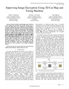
Abstract Delphi is a new geometry-guided predictive compression scheme for squeezing the connectivity of a triangluar mesh. The mesh is traversed using the Edgebreaker state machine. Instead of creating the Edgebreaker clers sequence both compression and decompression perform the same geometric prediction of the location of the unknown vertex of the next triangle during the mesh traversal. Based on this geometric prediction the connectivity is predicted , by snapping thepredicted vertex to the nearest boundary vertex, if one lies sufficiently close. If the guess is correct, a single confirmation bit is sufficient. Otherwise, an entropy-based code is received and used to encode the rectification of that prediction. For a series of meshes that we have tested, up to 97% of Dephi's predictions are correct, and result in a compressed connectivity format requiring between 0.19 and 1.5 bits per triangle. Categories and Subject Descriptors (according to ACM CCS): I.3.2 [Computer Graphics]: Graphics Systems distributed/network graphics; E.4 [Coding and Information Theory]: Data compaction and compression Keywords: lossless mesh compression, connectivity coding
1. Introduction 3D graphics plays an increasingly important role in applications where 3D models are accessed through the internet. Due to improved design and model acquisition tools, to the wider acceptance of this technology, and to the need for higher accuracy, the number and complexity of these models are growing faster than network bandwidth. Consequently, it is imperative to continue increasing the terseness of 3D data transmission formats. Although many representations have been proposed for 3D models, polygon and triangle meshes remain the de facto standard for exchanging and viewing 3D models. A triangle mesh may be represented by its vertex data and by its connectivity. It may be used directly as a polyhedral surface or as a coarse mesh controlling a subdivision surface. Most compression techniques separate the encoding of the connectivity information (triangle/vertex incidence) from the geometry information (vertex coordinates, and possibly their color or normal attributes). Already of theoretical interest fourty years ago24, lossless connectivity encoding has received over the last few years a significant amount of attention1, 4, 16, 21 because of its practical importance for the transmission of 3D models. Although several recent schemes are focused on progressive transmission2,3,7,10,14,22 or on computational simplicity9, 17, the reduction of the number of bits per triangle remains the primary objective. Furthermore, single-resolution encoding retains its strategic importance, because in most situations we know ahead of time that either the full resolution model or the coarse
starting point of a progressive model must be transmitted and because they can be more effectively encoded as single-resolution models than as progressive ones. In this paper, we propose a new encoding technique, called Delphi1, for single-resolution lossless compression of triangle mesh connectivity. Delphi is based on the Edgebreaker compression16 described in details in the next section. In Delphi, both compression and decompression perform the same geometric prediction of the location of the tip-vertex of the next triangle. They estimate the triangle connectivity by snapping the tip-vertex to the nearest boundary vertex, if one lies sufficiently close. If the guess is correct, only the confirmation bit needs to be transmitted. Because up to 97% of Dephi's guesses are correct, connectivity information is often compressed to a fraction of a bit per triangle, as reported below. 2. Previous work We focus in this section on techniques for the loss-less compression of the connectivity of triangle meshes. The connectivity of a “simple” mesh (defined as a connected, zero-genus, manifold triangle mesh) may be stored as a sequence of t triangle descriptors, each triangle been 1
The name is inspired by the ancient greek Oracle at Delphi, which worked similar to the proposed compression scheme. Pythia, the medium of the Oracle, responded to the questions in words unintelligible to all but a priest of Apollo, the god of truth, who would interpret the oracle and then relay the answers to the seeker.
2/9
Coors & Rossignac
represented by 3 integer labels. Each label identifies one amongst the v vertices and requires Èl o g2(v)˘ bits. Organizing triangles into strips5, where each new triangle shares an edge with the previous one, reduces the above storage by half in practice. The use of a buffer to cache a small number of labels4 may further reduce the expected cost. The Topological Surgery method of Taubin and Rossignac21 compresses both a triangle-spanning tree and its dual vertex-spanning tree by encoding the lengths of consecutive single-child nodes. Both trees suffice to decode the connectivity of the simple mesh. For complex and reasonably regular meshes, the expected cost of encoding both trees may amount to about two bits per triangle. However, the overhead of the run length encoding may result in a significantly higher average cost for irregular or small meshes. Rossignac's Edgebreaker compression scheme16, proposes both a rigorous theoretical analysis and an outstanding worst-case bound of the connectivity compression bit rate. The original method used at most 4 bit per vertex (denoted b/v for simplicity) and was improved to 3.6 b/v11. This upper-bound on storage does not rely on statistic-based entropy or arithmetic coding schemes, which in general perform poorly on small or irregular meshes. Consequently, Edgebreaker is particularly attractive for compressing large catalogs of small models. For large meshes, entropy codes further reduce the storage to less than 2 b/v17. Edgebreaker visits all the triangles of a mesh one at a time, walking from a previously visited triangle to one of its notyet visited neighbors through their common edge, called the “gate”. For manifold meshes, the tip of the new triangle is either a “new” vertex (case C) that has not yet been encountered or an “old” vertex of the boundary separating the previously visited portion of the mesh from the rest. Edgebreaker distinguishes four types of “old” vertices, depending on whether they appear in that boundary before the gate (case L) , after the gate (case R), both (case E), or neither (case S). The succession of case types produced by this traversal are encoded as a succession of symbols from the set
v
v
v
T
T
T
L
C
R
v
v
T
T
S
E
clers symbols are shown in Figure 1a. The arrow indicates the direction to the next triangle. Previously visited triangles are not shown. Note that in the case S, Edgebreaker moves to the right, using a recursive call, and then to the left. Figure 1b gives an example of the clers sequence of a small region of a simple mesh. A detailed description of the Edgebreaker compression and decompression and some extensions to non-manifold meshes are given in16 and18. Because half of the triangles correspond to case C in a manifold mesh, one may chose to encode them using a single bit (0), while the remaining four cases may be unambiguously encoded using 3 bits each (110 for L, 101 for R, 111 for E, and 100 for S). This simple code guarantees a 2 bits per triangle encoding. More complex codes11,8 guarantee to compress the Edgebreaker-generated clers sequence encoding of any zero-genus mesh to less than 1.8 bits per triangle. The clers sequence of meshes encountered in practice may be compressed even further, sometimes to less than 0.9 bits per triangle, using variablelength entropy codes17. When the mesh has a very large number of vertices and most of them have exactly six neighbors, the clers sequence can provably be compressed down to 0.81 bits per triangle19. A more efficient decompression algorithm, called Wrap&Zip17, interprets the clers sequence to build a simply connected triangulated polygon, which represents the triangle-spanning tree. Then, it zips up the borders of that polygon by matching pairs of its bounding edges in a bottom-up order with respect to the vertex-spanning-tree that is the dual of the triangle-spanning-tree. A previously proposed alternative, called Spirale Reversi9, interprets the reversed clers sequence and builds the triangle tree from the end. Touma and Gotsman23 also encode the vertices along a vertex-spanning tree. They distinguish only two cases, split and add, which correspond to the Edgebreaker's cases S and C. Other cases are not encoded. Instead, Touma and Gotsman also encode the degree of each vertex, i.e., the number of incident edges and use it to automatically identify the other cases. During decompression, they keep track of the number of already decoded triangles that are
R R
R L
C
L S
E C
E
R
R
Figure 1: (a) Edgebreaker clers symbols (b) example clers sequence: CRSRLECRRRLE {C,L,E,R,S}, called the clers sequence. For zero-genus meshes, the clers sequence is sufficient to represent the complete connectivity. These situations and the associated
incident upon each vertex and are thus capable of identifying the R, L, and E triangles automatically. Experimental results show that this schema compresses
3/9
Coors & Rossignac
connectivity down to less than 0.2 b/v for very regular meshes, and between 2 and 3.5 b/v otherwise, in practice. Alliez and Desbrun1 replace the deterministic traversal of Touma and Gotsman’s schema by an adaptive one in order to minimize the number of split operations. They adapt the traversal to avoid the creation of cavities (which lead to split operations) by attaching triangles to border edges that are incident to vertices with the smallest number of free edges. In Angle-Analzyer13 they use geometry to direct the mesh traversal such that the connectivity becomes predictable. To compress the vertex location, the connectivity of each case C triangle is used to access its neighbors and to predict the location of the tip-vertex. Then a corrective vector is transmitted to compensate for the error between the correct location and its prediction. In general, the distribution of corrective coordinates has lower entropy than the distribution of the original coordinates (e.q. they spread aroud zero). Therefore the corrective coordinates can be compressed with fewer bits on average.
3. Delphi Encoding for Edgebreaker In this section, we present a new geometry-guided predictive compression scheme for squeezing the clers sequence produced by the Edgebreaker mesh traversal, called Delphi encoding. For simplicity of the exposition, we focus on simply connected meshes that are homeomorphic to a sphere. The proposed approach applies to more complex meshes as well, but the cost analysis and encoding are more complex. The Delphi compression does not encode the clers sequence directly. Instead, it tries to guess each clers symbol and encodes the confirmation and the corrections to these guesses. The guess is based on the geometry and connectivity of the previously visited triangles. The Delphi decompression performs the same guesses and decodes a confirmation bit that either confirms that the guess is right or indicates that it is not, in which case a corrective string of subsequent bits will indicate the correct code. We call this sequence of confirmation bits and of corrections the Apollo sequence of the edgebreaker traversal. In contrast to the clers sequence decompression, we have to zip the mesh immediately while decoding the Apollo sequence. Otherwise, it is not always possible to perform the same guesses as during compression because the neighborhod of a triangle is not completely built. Consequently, when we encounter a S-case that is not correctly identified, we need to encode the identity of the old vertex that will serve as the tip-vertex of the S-triangle. This corresponds exactly to the reason that an offset I is necessary for the connect(i) operation of the cut-bordermachine6. In the following, we will explain how to guess the clers symbol of a triangle based on vertex geometry and how to build the Apollo-sequence.
3.1. Definitions A corner c is the association of a triangle c.t with one of its bounding vertices c.v. The next corner around a triangle in counterclockwise direction is denoted c.n, the previous corner c.p, and the opposite corner c.o. The location or geometry of the vertex v=c.v associated with the corner c is denoted c.v.g. As in the original Edgebreaker algorithm, we move from a triangle F to an adjacent triangle T at each step of the mesh traversal. F and T share a common edge G, called gate. Let c be the corner of T that is not incident upon G as shown in Figure 2. Let Length(G) denote the length of the gate. The transmitted information must identify the vertex c.v. Let g(c) be the estimate on the location of c.v.g. For instance, we can compute g(c) using the parallelogram rule22: g(c) = c.n.v.g+c.p.v.g–c.o.v.g. Let B denote the set of all vertices in the decoded mesh which are not interior to the mesh. As we have assumed that the mesh is simply connected, the vertices of B form one or several cyclic chains {c.p.v, Vr, V2, …Vl, c.n.v}, called hereafter “loops”, along the oriented border. One of these loops contains the gate. We will call it the “active loop”. For zero-genus meshes, we know that c.v is part of the active loop. Let B’ be the set of vertices of the active Already traversed area Active loop
d
g(c)
c
Vl
c.v v
c.n c.p
X Vr
c G c.o
c Figure 2: Connectivity guessed by parallelogram prediction loop excluding the gate vertices c.n.v and c.p.v. Let X be the vertex of B’ that is the closest to g(c). Let d:=Dist(X,g(c)) denote the distance between them. X is a prime candidate for c.v. We will use d to decide whether X is our guess or whether we are guessing that c.v is a new vertex. 3.2. Connectivity prediction Specifically, when d exceeds a threshold, we assume a C triangle. The difference gp=c.v.g-g(c) of the prediction g(c) and the vertex location c.v.g will be encoded. When d is smaller than the threshold, X will be our guess and if that guess is correct, we will have one of the four cases L, E, R,
4/9
Coors & Rossignac
Guess C in X
g(c)
g(c)
g(c)
X
X Guess C
Guess L
g(c)
X
g(c)
Guess R X
X g(c)
Situation R Guess S
X
g(c)
Situation L
Guess E
X X g(c)
Figure 3: Guess clers Symbol based on geometry prediction.
g(c)
or S, depending on whether X is V1, or Vr, or both, or neither. The threshold is based on the length of the gate G. More precisely, if d>t*Length(G), with a constant t=0.6 for example, we guess T is of type C. Otherwise, we guess that c.v is X and distinguish four situations as shown in Figure 3: •
If X is both V1 and Vr, then we guess that T is of type E.
•
If X is Vr, then we guess that T is of type R.
•
If X is Vl, then we guess that T is of type L.
•
Otherwise, we guess that T is of type S.
Situation S
Figure 4: Wrongly guesses C triangles was wrong.The subsequent bits would clarify its type. If the length of the active loop |B’| is equal 1, the triangle has to be of type E. No further information is necessary. If |B’|=2, only two possible symbols {L, R} have to be distinguished. Otherwise, it is necessary to distinguish between the three remaining cases in {L, R, S}, because an E situation is impossible. In case of a mis-classified type S triangle at the most Èlog2(|B’|)˘ bits are needed to encode the identity of c.v in order to enable immediately zipping during decoding. However, experimental results have shown that in most cases the offset is 2 or 3. Only 2 bit are sufficient to decode these offsets. Without these bits, it would not be possible to perform the same guesses during decompression as during compression.
A single bit in the transmission stream suffices to indicate whether our guess is correct. If so, we not only know the code of T (i.e., we have decoded its Edgebreaker symbol using one bit), but we also know which vertex it is and can thus zip the border immediately during decompression, avoiding the zip delays introduced in17 and not requiring the transmission of offsets that are associated with S triangles6, 23 to identify the tip-vertices of S triangle. Of course, our guess can be wrong. In this case we need some information in order to rectify the guess. Note that a false guess does not necessarely indicate a wrong symbol. We might wrongly guess c.v as X and concluded a S situation. In fact, it might be an S situation, but with another tip in B’. In the following, we discuss that rectification depending on the guessed symbol and the length of the active border. We discuss below how we encode the rectification of the wrong guesses. We start with the case where we guessed a C and made a mistake as shown in figure 4. Then we discuss the cases where we wrongly guessed L, R, S, or E (see figure 5). •
If we guessed a C, and in fact c.v is a vertex in B’, one bit in the transmission stream indicates that our guess
Situation E
•
If we wrongly guess case E (X=V1 and X=Vr), it must be a C situation. (An E is guessed only with |B’|=1. With only one border vertex, situations L, R, and S are not possible.) The confirmation bit is sufficient. No additional bits are necessary to rectify the guess.
•
If we wrongly guess case R (X=Vr), the subsequent bits are used to distinguish between the three remaining symbols {L, C, S}. An E symbol is not possible here.
•
If we wrongly guess case L (X=V1), we have to distinguish between the remaining symbols {R, C, S}. Again, an E symbol is not possible in this situation.
5/9
Coors & Rossignac
Guess wrong L
Guess wrong R
g(c)
g(c) X
Situation L
X Situation C
g(c)
g(c) X
X
Guess wrong S
g(c)
g(c)
X
Situation R
Situation S
g(c) X
Situation C
Situation S
Guess wrong E
X
g(c)
X
g(c)
X
g(c)
X
X g(c)
Situation C
Situation R
Situation L
Situation C
Situation S
Figure 5 Wrongly guessed non-C triangles. They grey triangle shows the actual situation. The yellow triangle visualizes the parallelogram prediction. If we wrongly guess case S, the four remaining symbols {C, L, R, S} are possible. (An E symbol is not possible here, because an E situation occures only with | B’|=1, which implies V1=Vr. In this case, we would have never guessed S, only a C or E.) Even if S is the the correct guess, the tip-vertex might not be X. So, when the correction states that the guess of S is correct but the tip is wrong, additional bits must be transmitted to identify the correct tip-vertex in the active loop. These situations are rare because the number of S cases is relatively small and many of them are correctly identified.
wrong, and an additional bit distinguishes between a C and L situation.
Taking into account the current length of the active border |B’|, some cases are not possible and the bit code for the correction can be shortened.
Using the proposed connectivity prediction, an Edgebreaker mesh traversal can be expressed by a sequence of 3-tupel A=(G, RS, SO), where G is the confirmation bit indicating whether the guess is correct or not, R is the correction string in case of a false guess, and SO is the offset in a wrongly guessed S situation. This sequence is called the Apollo sequence, because it is used to interpret the connectivity guess. The Apollo sequence is equivalent to the Edgebreaker clers sequence. Figure 6 shows the Apollo sequence of the above introduced example (see figure 1).
•
If |B’|=1, only cases C and E are possible. |B’|=1 implies V1=Vr. L, R and S situations are not possible. In this case, the validation bit suffices to distinguish between the two possible cases: C or E. An active loop length |B’|=2, implies that B’ only contains the vertices V1 and Vr. Neither an E nor a S situation are possible in this case. If the guess is wrong, one additional bit is sufficient to rectify the situation. For example, in case of a wrongly guessed R, one bit indicates that the guess is
Finally, when |B’|=3, there is only one vertex in the active border besides V1 and Vr and thus that vertex is the only acceptable tip-vertex for an S case. There is no need to send corrective bits to dentify the tip in a wrongly guessed S triangle. Furthermore, a wrongly guessed S case cannot be an S with a different tip-vertex. Using a careful analysis of these situations and exploiting the restrictions described above, we hade devised and evaluated several variable length schemes for encoding the corrective string of bits.
To analyse the behavior of Delphi and to report the associated statistics, we store an augmented Appollo sequence in which we also include the guessed symbol GS and the length of the active loop |B’| leading to tuples
6/9
Coors & Rossignac
Figure 6: Example Apollo encoding: Let us assume that we guessed the first triangle of the example correctly as type C. We than predict the tip of the right triangle at g(c) using the parallelogram rule. Since the distance of g(c) and the active border is too large, we guess again a type C triangle. Unfortunately, that guess was wrong. In fact, the right triangle, shown in gray color in the first picture, is of type R. In the Apollo sequence we encode this situation as (f,R) and continue the traversal with the left triangle of R. The prediction scheme is performed for all triangle in Edgebreaker sequence and leads to the following Apollo sequence: ((t), (f, R), (t), (t), (t), (t), (t), (t), (t), (f,R), (t), (t), (t)). With a trivial encoding scheme we can compress this sequence with 16 bits instead of 32 bits for the corresponding clers sequence. A’=(G, RS, SO, GS, |B’|). Note that GS and |B’| are known by the decoder during decompression. There is no need to transmit this information. It is included only for analysis purposes.
3.3. Encoding the Apollo sequence A simply connected regular mesh with t triangles can be expressed by an Apollo sequence of length t-1. Each Apollo tuple corresponds to a symbol of the equivalent clers sequence of that mesh. In order to achive a compact mesh representation, the Apollo sequence has to be encoded efficiently. The layers of this compression will be discussed separately: •
The guess layer,
•
The rectified symbol layers
•
The tip offset layer
These layers can be compressed using an adaptive entropy encoder like the range encoder as in1 for example.
However, compression results vary using different encoders. The entropy of the Apollo sequence as a lower bound for the compression ratio gives more insight about the encoded information. A good entropy encoder will come close to that bound. We can treat each layer M of the Apollo sequence as a markov source of order n20. The conditional entropy H(M|sj) of such a markov source is given by H(M|sk) = -Â p(mi|sk)* log2(p(mi|sk)), where sk= sk1…skn is the sequence of the n previous symbols. The entropy of an ergodic markov source of order n is then given by H(M)= Â p(sk)* H(M|sk). Note that H(M) is always less than or equals the entropy H(M)= -Â p(mi)* log2(p(mi)) where M denotes the same source without memory. We will treat the layers as sequences of first order markov sources (n=1). The first order entropy of these layers is a
Coors & Rossignac
lower bound for the compression ratio of the Apollo sequence. In addition to that lower bound and a practical compression rate, a guaranteed upper bound is fundamental for a number of applications where compression will be performed at runtime. The upper bound on the number of bits per vertex is needed here to estimate the maximum expected time for transmission. The upper bound of the Apollo sequence mainly depends on the quality of the prediction. If the prediction is often wrong, a lot of rectification information is necessary and the code will become inefficient. In that case, the original clers sequence should be used instead. Because both encode the same mesh traversal, the clers sequence can be directly derived from the Apollo sequence. For that reason, the worst case upper bound of 3.6 bits per triangle from Edgebreaker is also valid for Delphi compression. However, if the prediction is often correct, the upper bound will be much less than in Edgebreaker. The Apollo sequence contains t-1 symbols mi Œ{t, f} in the guess layer MG. A trivial code will use 1 bit for each symbol in that layer. Let p(t) be the probability of a correct guess. The propability p(f) of a wrong guess is given by p(f)=1-p(t). In case of a wrong guess 2 bits are sufficient to encode the rectified symbol in any case. However, this is a rough estimate. If the guessed symbol GS is a E it must be a C situation. No further information is needed to rectify the guess. If GS is a L or R a simple Huffman code will need less than 1.7 bits per symbol to distinguish the three possible retified symbols. In case of a wrongly guessed C symbol also 1.7 bits are sufficient to distinguish the three rectified symbols L, R, and S. The E symbols which might occur as rectification do not have to be encoded. Only in case of |B’|=1 an E symbol is possible and in that case, no other symbol besides C is valid. If the guess says that C was wrong, it must be an E. Only in case of a wrongly guessed S, four different recified symbols C, L, R, ,and S have to be distinguished.
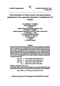
7/9 Experimental results lead to 80% to 95% of correct guesses for regular meshes. The estimated upper bound is between 1.34 to 1.1 bits per triangle for these meshes. In practice, the compression bit rate was between 0.8 and 0.2 bits per triangle or 1.6 and 0.4 bits per vertex in these cases. 3.4. Decoding While decoding the Apollo sequence, the decompression algorithm (Pythia) predicts the clers symbol of the new triangle using the same prediction scheme as during compression. This guess is interpreted using the corresponding Apollo tupel. If the guess is correct, we can restore that triangle and because we guessed not only the correct symbol but also the correct tip of the triangle in the active loop in case of a non-C triangle, we can zip immediately and restore the mesh connectivity. If the Apollo tupel indicates that the guess was wrong, we will get the rectified symbol RS and the offset SO in addition. This information suffices again to restore the new triangle and immediately zip it. 4. Experimental results In this chapter a detailed analysis of the Apollo sequence of one example mesh is given. Additonally, the bit rate of a series of test meshes is compared with other connectivity compression schemes. 4.1. The Horse Model In the following the Apollo sequence of a mesh that represents a horse model with 96966 triangles and 48485 vertices as shown in figure 7 will be analysed in detail.
If the of a rectified symbol RS is a S, the tip of that type S triangle has to be encoded in order to zip it immediately. In case of a manifold mesh with genus 0, that tip is a vertex on the active loop and can be encoded by the topological distance s to Vr on the active loop. Experimental results have shown that s is 2 or 3 in most cases. However, this offset is a serious obstacle to guarantee a linear worst case bit-rate. Theoretically, log2(|B’|) are needed to encode the tip of that S triangle. Nevertheless, we can estimate an upper bound, if the number of S triangles is supposed negligible. The guess layer needs less than one bit per triangle. In addition, for each wrong guess, less than 2 bit are needed to rectify the guess. If the number of S triangles is small, 1.7 bit is sufficient because a rectified S does not often occur. Summing up, an estimated upper bound bit rate b is given by b=1+1.7*p(f) bits per triangle. In other words, Delphi compression is more efficient than Edgebreaker, if more than 65% of the predictions are true.
Figure 7: Delphi compression of the horse model (96966 triangles). Correctly predicted triangles are colored green, wrong ones red. About 83% of the connectivity is correctly guessed leading to a bit rate of 1.47 b/v. The accompanying video shows the mesh traversal in detail.
8/9
Coors & Rossignac
Table 1 shows the distribution of correctly and wrongly guessed triangles. P(t) 0.8290 P(f) 0.1710 P(|B’|=1|f ) 0.0162 P(|B’|=2|f ) 0.0025 P(|B’|>=3|f) 0.9813 Table 1: Probability of wrong guesses About 83% of the connectivity is correctly guessed using the parallelogram prediction. In case of a wrong guess, the conditional probability of the length of the active border is reported. In case of an active loop length |B’|=1 no additional information is necessary to rectify the guess. If the active loop length is 2, one bit is sufficient to rectify the guess as shown in 3.2. However, most of the wrong guesses occur in an active loop with length greater than 2 as expected. The next table shows the probability PXY of a wrongly guessed symbol GS=X and its rectification RS=Y in case of an active border length greater than or equals 3: PXY=P(RS=Y Ÿ GS=X |ÿG Ÿ |B’|>=3 ). PXY GS=C GS=L GS=R GS=S Sum
RS=C -0.0082 0.2751 0.0580 0.3413
RS=L 0.0033 -0.0013 0.0003 0.0049
RS=R 0.5209 0.0067 -0.0932 0.6208
RS=S 0.0143 0.0004 0.0163 0.0020 0.0330
Sum 0.5385 0.0153 0.2927 0.1535 1.0000
Table 2 Probability of rectified symbols When a guessed C (GS=C) proves to be wrong the correct symbol is usually R, and vice versa, in case of a wrong guess GS=R, most rectified symbols are C. An entropy encoder will take advantage out of that distribution. Another interesting fact is that a rectified symbol S occurs in 3% of wrong guesses. In that case, an offset is needed to encode the tip of that S triangle. This offset is given as the topological distance of the tip of Vr on the active loop. Table 3 shows the distribution of that offset. The offset is 2 in 90% and 3 in 6% of all rectified S triangles, and is encoded with less than 1.1 bit in these cases. The expensive part is the encoding of the remaining 4% where the offset is greater than 3. However, this occurs only in 0.02% of all triangles (in this example 20 triangles) and, for the models we have tested, the offset did not excede 560. Offset 2 3 >3 (max 560)
4.2. Experimental Comparison A series of meshes was tested with the new Delphi compression using paralleogram prediction. The connectivity compression results are given in bits per vertex of the calculated first order entropy encoding. The results are compared with the first order entropy of the corresponding Edgebreaker clers sequence (EB). Actual bis-rates are slightly higher because they carry an overhead depending on the used arithmetic/huffmann/range encoder. The results show that a good connectivity guess improves Edgebreaker clers sequence compression. For very good connectivity guesses like the Mannequin model, the Apollo encoding improves Edgebreaker by a factor 3. When the probability of a wrong guess exede 40% the Delphi encoding stops being advantageous.
Model Horse
#V
48485 96966 1,47 (83%)
Cow
2904
Body
711
Mannequin Venus Neferiti David
Delphi bpv (p(t)) EB
#T
5804
1,75
1,6 (83%)
2,26
1396 2,25 (65%)
2,59
11704 23402 0,41 (97%)
1,2
8268 16532 2,84 (59%)
2,86
299
562 2,17 (69%)
24085 47753
2,9 (58%)
2,58 2,79
Table 4 Compression results (in bits per vertex).The percentage of correct guesses is given for the Delphi compression.
0.9 0.06 0.04
Table 3 Offset distribution in case of RS=S The above introduced first order entropy compression leads to 1.47 bits per vertex connectivity encoding using a parallel prediction scheme in order to guess the mesh connctivity. The corresponding edgebreaker traversal of that model has a first order entropy of 1.75 which leads to an improvement of 15%.
Figure 8: 3D meshes used for bit-rate measurements. 5. Conclusion and future work In this paper, we described a lossless, single-resolution connectivity encoding technique called Delphi. In contrast
9/9
Coors & Rossignac
to previously published connectivity compression schemes Delphi uses the previously decoded geometric and connectivity to predic the location of the tip-vertex of the next triangle. We discuss here how this prediction is used to compress connectivity. The geometry prediciton, which is based on the parallelogram rule, is not affected by the Delphi encoding and thus has identical characteristics to previously reported schemes23 for geometry compression. Delphi uses the same mesh traversal and the same mapping of the connectivity of the mesh into a clers sequence as Edgebreaker. Because of the accuracy of its connectivity prediction scheme, Delphi’s encoding of the clers sequence results in significant compression gains. 6. References 1. Alliez, P. and Desbrun, M. Valence-Driven Connectivity Encoding for 3D Meshes. Eurographics 2001 Conference Proceedings, 2001
13.
Lee, H., Alliez, P., and Desbrun, M. Angle-Analyzer: A Triangle-Quad Mesh Codec, Eurographics 2002 Conference Proceedings, 2002
14.
Pajarola, R. and Rossignac, J. “Compressed Progressive Meshes.” IEEE Transactions on Visualization and Computer Graphics, pp 47-61, 1999
15.
J. Rossignac and D. Cardoze, “Matchmaker: Manifold Breps for non-manifold r-sets”, Proceedings of the ACM Symposium on Solid Modeling, pp. 3141, June 1999.
16.
J. Rossignac, "Edgebreaker: Connectivity compression for triangle meshes", IEEE Transactions on Visualization and Computer Graphics, 5(1), 47-61, Jan-Mar 1999.
17.
J. Rossignac and A. Szymczak, "Wrap&Zip decompression of the connectivity of triangle meshes compressed with Edgebreaker", Computational Geometry, Theory and Applications, 14(1/3), 119135, November 1999.
2.
Alliez, P. and Desbrun, M. Progressive Encoding for Lossless Transmission of 3D Meshes. Siggraph 2001 Conference Proceedings, 2001
3.
Cohen-Or, D., Levin, D., and Remez, O., Progressive Compression of Arbitrary Triangular Meshes. Visualization 99 Conference Proceedings, pp 67-72, 1999
18.
J. Rossignac, A. Safonova, and A. Syzmczak, "3D Compression Made Simple: Edgebreaker on a Corner-Table", Invited lecture at the Shape Modeling International Conference, Gemoa, Italy, May 2001.
4.
M. Deering, M. Geometry Compression, Computer Graphics, Proceedings Siggraph'95, 13-20, August 1995.
19.
5.
F. Evans, S. Skiena, and A. Varshney, Optimizing Triangle Strips for Fast Rendering, Proceedings, IEEE Vizualization'96, pp. 319--326, 1996.
A. Szymczak, D. King, J. Rossignac, “An Edgebreaker-based Efficient Compression Scheme for Connectivity of Regular Meshes”, Special issue of Journal of Computational Geometry: Theory and Applications, Vol 20, No 2, Oct 2001.
20.
6.
S. Gumhold and W. Strasser, “Real Time Compression of Triangle Mesh Connectivity”, Proc. ACM Siggraph, pp. 133-140, July 1998.
H. Tzschach, and G. Haßlinger, “Codes für den störungsfreien Datentransfer”, Oldenburg 1993 (in german)
21.
7.
Hoppe, H., Progressive Meshes. Siggraph 96 Conference Proceedings, pp 99-108, 1996
G. Taubin and J. Rossignac, "Geometric Compression through Topological Surgery", ACM Transactions on Graphics, 17(2), 84-115, April 1998.
8.
Gumhold, S., Towards optimal coding and ongoing research, 3D Geometry Compression Course Notes, SIGgraph 2000
22.
Taubin, G, Gueziec, A. Horn, W. and Lazarus, F. Progressive Forest Split Compression. Siggraph 98 Conference Proceedings, pp 123-132, 1998
9.
Isenburg, M. and Snoeyink, J., “Spirale Reversi: Reverse decoding of the Edgebreaker encoding”, Tech. Report TR-99-08, Computer Science, UBC, 1999.
23.
C. Touma and C. Gotsman, “Triangle Mesh Compression”, Proceedings Graphics Interface 98, pp. 26-34, 1998.
24.
10.
Khoddakovsky, A., Schroeder, P. and Sweldens, W. Progressive Geometry Compression. Siggraph 2000 Conference Proceedings, pp 271-278, 2000.
Tutte, W. A Census of Planar Triangulations. Canadian Journal of Mathematics, 14:21-38, 1962
11.
King, D. and Rossignac, J. “Guaranteed 3.67V bit encoding of planar triangle graphs”, 11th Canadian Conference on Computational Geometry (CCCG'’99), pp. 146-149, Vancouver, CA, August 15-18, 1999.
12.
D. King, D. and J. Rossignac, J., "Connectivity Compression for Irregular Quadrilateral Meshes" Research Report GIT-GVU- 99 -29, Dec 1999.