Vol. 26, No. 15 | 23 Jul 2018 | OPTICS EXPRESS 19548
Demonstration of color display metasurfaces via immersion lithography on a 12-inch silicon wafer TING HU,1,* CHIH-KUO TSENG,1 YUAN HSING FU,1 ZHENGJI XU,1 YUAN DONG,1 SHIJIE WANG,1 KENG HENG LAI,1 VLADIMIR BLIZNETSOV,1 SHIYANG ZHU,1 QUNYING LIN,1 AND YUANDONG GU1,2 1
Institute of Microelectronics, Agency for Science, Technology and Research (A*STAR), 2 Fusionopolis Way, #08-02, Innovis, Singapore 138634, Singapore 2
[email protected] *
[email protected]
Abstract: The demonstration of a color display metasurface on a 12-inch silicon wafer with critical dimension (CD) below 100 nm by complementary metal-oxide semiconductor (CMOS) compatible technology is reported for the first time. The 193 nm ArF deep UV immersion lithography is leveraged instead of electron beam lithography (EBL) to pattern the metasurface, which greatly improves the efficiency while keeping a high resolution. The demonstrated metasurface successfully generates the resonant modes and reflects the lights at resonance wavelengths, giving its display in red, green, and blue (RGB) colors. The waferlevel uniformities of CD and reflection characteristic of the metasurface are measured and analyzed. The experimental data show that they are well controlled in the fabrication process. The work provides a promising route towards mass production of dielectric metasurfaces. © 2018 Optical Society of America under the terms of the OSA Open Access Publishing Agreement OCIS codes: (220.0220) Optical design and fabrication; (110.4235) Nanolithography; (110.5220) Photolithography; (310.6628) Subwavelength structures, nanostructures.
References and links 1. 2.
N. Yu and F. Capasso, “Flat optics with designer metasurfaces,” Nat. Mater. 13(2), 139–150 (2014). M. Khorasaninejad and F. Capasso, “Metalenses: Versatile multifunctional photonic components,” Science 358(6367), eaam8100 (2017). 3. O. Avayu, E. Almeida, Y. Prior, and T. Ellenbogen, “Composite functional metasurfaces for multispectral achromatic optics,” Nat. Commun. 8, 14992 (2017). 4. S. Zhang, M.-H. Kim, F. Aieta, A. She, T. Mansuripur, I. Gabay, M. Khorasaninejad, D. Rousso, X. Wang, M. Troccoli, N. Yu, and F. Capasso, “High efficiency near diffraction-limited mid-infrared flat lenses based on metasurface reflectarrays,” Opt. Express 24(16), 18024–18034 (2016). 5. A. L. Kitt, J. P. Rolland, and A. N. Vamivakas, “Visible metasurfaces and ruled diffraction gratings: a comparison,” Opt. Mater. Express 5(12), 2895–2901 (2015). 6. Z. Xu, T. Li, D.-H. Zhang, C. Yan, D. Li, L. Y. M. Tobing, F. Qin, Y. Wang, X. Shen, and T. Yu, “Groovestructured metasurfaces for modulation of surface plasmon propagation,” Appl. Phys. Express 7(5), 052001 (2014). 7. G. Li, L. Wu, K. F. Li, S. Chen, C. Schlickriede, Z. Xu, S. Huang, W. Li, Y. Liu, E. Y. B. Pun, T. Zentgraf, K. W. Cheah, Y. Luo, and S. Zhang, “Nonlinear metasurface for simultaneous control of spin and orbital angular momentum in second harmonic generation,” Nano Lett. 17(12), 7974–7979 (2017). 8. M. Pu, X. Ma, Z. Zhao, X. Li, Y. Wang, H. Gao, C. Hu, P. Gao, C. Wang, and X. Luo, “Near-field collimation of light carrying orbital angular momentum with bull’s-eye-assisted plasmonic coaxial waveguides,” Sci. Rep. 5(1), 12108 (2015). 9. F. Ding, Z. Wang, S. He, V. M. Shalaev, and A. V. Kildishev, “Broadband high-efficiency half-wave plate: a supercell-based plasmonic metasurface approach,” ACS Nano 9(4), 4111–4119 (2015). 10. P. C. Wu, W.-Y. Tsai, W. T. Chen, Y.-W. Huang, T.-Y. Chen, J.-W. Chen, C. Y. Liao, C. H. Chu, G. Sun, and D. P. Tsai, “Versatile polarization generation with an aluminum plasmonic metasurface,” Nano Lett. 17(1), 445– 452 (2017). 11. C. H. Chu, M. L. Tseng, J. Chen, P. C. Wu, Y.-H. Chen, H.-C. Wang, T.-Y. Chen, W. T. Hsieh, H. J. Wu, G. Sun, and D. P. Tsai, “Active dielectric metasurface based on phase-change medium,” Laser Photonics Rev. 10(6), 1063 (2016).
#332891 Journal © 2018
https://doi.org/10.1364/OE.26.019548 Received 30 May 2018; revised 1 Jul 2018; accepted 1 Jul 2018; published 18 Jul 2018
Vol. 26, No. 15 | 23 Jul 2018 | OPTICS EXPRESS 19549
12. E. Arbabi, A. Arbabi, S. M. Kamali, Y. Horie, M. Faraji-Dana, and A. Faraon, “MEMS-tunable dielectric metasurface lens,” Nat. Commun. 9(1), 812 (2018). 13. L. Zhang, J. Ding, H. Zheng, S. An, H. Lin, B. Zheng, Q. Du, G. Yin, J. Michon, Y. Zhang, Z. Fang, M. Y. Shalaginov, L. Deng, T. Gu, H. Zhang, and J. Hu, “Ultra-thin high-efficiency mid-infrared transmissive Huygens meta-optics,” Nat. Commun. 9(1), 1481 (2018). 14. S. Wang, P. C. Wu, V.-C. Su, Y.-C. Lai, C. Hung Chu, J.-W. Chen, S.-H. Lu, J. Chen, B. Xu, C.-H. Kuan, T. Li, S. Zhu, and D. P. Tsai, “Broadband achromatic optical metasurface devices,” Nat. Commun. 8(1), 187 (2017). 15. B. H. Chen, P. C. Wu, V. C. Su, Y. C. Lai, C. H. Chu, I. C. Lee, J. W. Chen, Y. H. Chen, Y. C. Lan, C. H. Kuan, and D. P. Tsai, “GaN metalens for pixel-level full-color routing at visible light,” Nano Lett. 17(10), 6345–6352 (2017). 16. W. T. Chen, A. Y. Zhu, V. Sanjeev, M. Khorasaninejad, Z. Shi, E. Lee, and F. Capasso, “A broadband achromatic metalens for focusing and imaging in the visible,” Nat. Nanotechnol. 13(3), 220–226 (2018). 17. S. Wang, P. C. Wu, V.-C. Su, Y.-C. Lai, M.-K. Chen, H. Y. Kuo, B. H. Chen, Y. H. Chen, T.-T. Huang, J.-H. Wang, R.-M. Lin, C.-H. Kuan, T. Li, Z. Wang, S. Zhu, and D. P. Tsai, “A broadband achromatic metalens in the visible,” Nat. Nanotechnol. 13(3), 227–232 (2018). 18. B. Groever, W. T. Chen, and F. Capasso, “Meta-lens doublet in the visible region,” Nano Lett. 17(8), 4902–4907 (2017). 19. M. Khorasaninejad, A. Y. Zhu, C. Roques-Carmes, W. T. Chen, J. Oh, I. Mishra, R. C. Devlin, and F. Capasso, “Polarization-insensitive metalenses at visible wavelengths,” Nano Lett. 16(11), 7229–7234 (2016). 20. T. Paul, A. Matthes, T. Harzendorf, S. Ratzsch, and U. D. Zeitner, “Half-wave phase retarder working in transmission around 630nm realized by atomic layer deposition of sub-wavelength gratings,” Opt. Mater. Express 5(1), 124–129 (2015). 21. Y. Yang, W. Wang, P. Moitra, I. I. Kravchenko, D. P. Briggs, and J. Valentine, “Dielectric meta-reflectarray for broadband linear polarization conversion and optical vortex generation,” Nano Lett. 14(3), 1394–1399 (2014). 22. H.-C. Wang, C. H. Chu, P. C. Wu, H.-H. Hsiao, H. J. Wu, J.-W. Chen, W. H. Lee, Y.-C. Lai, Y.-W. Huang, M. L. Tseng, S.-W. Chang, and D. P. Tsai, “Ultrathin planar cavity metasurfaces,” Small 14(17), e1703920 (2018). 23. V.-C. Su, C. H. Chu, G. Sun, and D. P. Tsai, “Advances in optical metasurfaces: fabrication and applications,” Opt. Express 26(10), 13148–13182 (2018). 24. M. L. Tseng, P. C. Wu, S. Sun, C. M. Chang, W. T. Chen, C. H. Chu, P.-L. Chen, L. Zhou, D.-W. Huang, T.-J. Yen, and D. P. Tsai, “Fabrication of multilayer metamaterials by femtosecond laser-induced forward-transfer technique,” Laser Photonics Rev. 6(5), 702–707 (2012). 25. C. H. Chu, M. L. Tseng, C. D. Shiue, S. W. Chen, H.-P. Chiang, M. Mansuripur, and D. P. Tsai, “Fabrication of phase-change Ge2Sb2Te5 nano-rings,” Opt. Express 19(13), 12652–12657 (2011). 26. A. She, S. Zhang, S. Shian, D. R. Clarke, and F. Capasso, “Large area metalenses: design, characterization, and mass manufacturing,” Opt. Express 26(2), 1573–1585 (2018). 27. Z. Dong, J. Ho, Y. F. Yu, Y. H. Fu, R. Paniagua-Dominguez, S. Wang, A. I. Kuznetsov, and J. K. W. Yang, “Printing beyond sRGB color gamut by mimicking silicon nanostructures in free-space,” Nano Lett. 17(12), 7620–7628 (2017).
1. Introduction Metasurfaces, consisting of sub-wavelength structure arrays with single-layer or multi-layer stacks, have recently attracted enormous attention as a promising platform for the development of flat optics [1,2]. The sub-wavelength structures which compose metasurfaces enable the precise engineering of the light wavefront. Through tailoring the amplitude, phase and polarization of the light, metasurfaces can realize the functions as the conventional optical components made in the bulk form, while provide the advantages of miniaturized size, decreased weight, and complementary metal-oxide semiconductor (CMOS) -compatible fabrication process. Both metal [3–10] and dielectric materials [11–13,16–21] were used to form the metasurfaces. The dielectric materials based metasurfaces outperform due to the ease for process integration and the higher transmission efficiency. Remarkable progresses have been made in demonstration of flat optic components by dielectric metasurfaces, including focusing metalens [3,4,6,12–15], collimator [8], wave plate [9,20], polarization generator [21], planar cavity [22] and so on. However, most of the works were based on the electron beam lithography (EBL) for metasurface patterning, which is not suitable for mass manufacturing. Other fabrication techniques for metasurfaces have been discussed or utilized in [23–25]. Among these techniques, only nano-imprint has the merit of mass production as the traditional photolithography, but it is challenge to make the high resolution mold and remove the residual imprint layer clearly. Recently, She et al. reported a metalens fabricated by 4-inch stepper lithography [26], but only with a relatively large critical dimension (CD) of several hundreds of nanometers, which limits its application only at infrared range. For
Vol. 26, No. 15 | 23 Jul 2018 | OPTICS EXPRESS 19550
applications at shorter wavelengths, e.g. visible light, metasurfaces with sub-hundred nanometer CD is required. Thus, the highly efficient and precise lithography should be utilized for mass production of metasurfaces. In this paper, we first report the implementation of amorphous silicon (a-Si) metasurface on a 12-inch wafer by 193 nm ArF deep UV (DUV) immersion lithography and ICP etching, to demonstrate the feasibility of mass production for dielectric metasurfaces. A metasurface, consisting of cylindrical a-Si pillars with CD below 100 nm, is designed to realize the display of red, green and blue (RGB) colors. The dimensions of a-Si pillars are determined by 3D Finite-Difference Time-Domain (FDTD) simulation. The reflectance spectra of the metasurface are measured and analyzed. In addition, the variations of CD and device performance over the entire wafer are characterized and discussed. 2. Device design and simulation
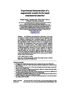
Fig. 1. (a) Schematic configuration of the color display metasurface with a-Si nanopillar array. The simulated (b) λR and (c) reflectance of the metasurface vs. diameter D of nanopillar. (d) Simulated reflectance spectra when D is set as 170 nm, 120 nm and 70 nm with period of 300 nm, 250 nm and 200 nm, respectively. The insets in Fig. 1(d) show the optical fields of resonant modes at wavelength of 577 nm for pillar diameter of 120 nm.
The schematic structure of the designed metasurface working at visible light is shown in Fig. 1(a). It is built up by sub-wavelength cylindrical a-Si pillars. The 70 nm-thick silicon nitride (SiN) layer between the metasurface and Si substrate serves as the bottom cladding with low refractive index. The pillar diameter, height and period are denoted as D, H and P, respectively. If a visible light irradiates on the metasurface perpendicularly, localized resonances is generated, resulting in the reflection of light at the resonance wavelengths. The color corresponding to the reflected wavelengths is displayed by the metasurface [27]. In order to display RGB colors, the 3D FDTD simulation is employed to find appropriate values of D, H and P. The wavelength of reflectance peak (λR) as a function of D is simulated and shown in Fig. 1(b). As seen, λR is red-shift with the increasing of pillar diameter. The values
Vol. 26, No. 15 | 23 Jul 2018 | OPTICS EXPRESS 19551
of D are chosen as 170 nm and 120 nm with period of 300 nm and 250 nm, to obtain the λR at 668 nm (for red color) and 577 nm (for green color), respectively. In the simulation, λR in the blue light wavelengths is not found, thus it is not plotted in Fig. 1(b). However, weak reflection in blue light range can still be utilized to display the blue color. Hence the reflectance of the metasurface is simulated to determine D for blue display. As seen in Fig. 1(c), the reflectance at wavelength of 420 nm is around 20% with D = 50 nm, and it decreases to ~8% when D is equal or larger than 70 nm. Considering our lithography capability (D ≥ 60 nm) and leaving some room for tolerance, 70 nm of D is adopted for the pillars to display blue color. Figure 1(d) shows the simulated reflectance spectra when the pillar diameters are set as 170 nm, 120 nm and 70 nm with period of 300 nm, 250 nm and 200 nm, respectively. The optical fields of resonant modes at the wavelength of 577 nm (D = 120 nm, P = 250 nm) are shown in the insets of Fig. 1(d). One can see that the electric and magnetic fields are strongly confined within the a-Si pillar, which leads to the reflection of green light. In the simulation of Figs. 1(b)-1(d), pillar height is set as 130 nm. Through the adjusting of the period of pillar array, the reflection efficiency can be improved. 3. Fabrication and characterization
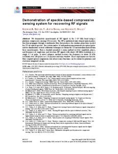
Fig. 2. (a) Photograph of the fabricated 12-inch wafer. (b) Close view of one die on the wafer with the colored logo “IME”. (c)-(e) SEM images of a-Si nanopillar arrays for the three letters “I”, “M” and “E”, respectively.
The device fabrication started with a 12-inch Si wafer. A 70 nm-thick SiN layer and a 130 nm-thick a-Si layer were deposited successively on the Si substrate using the plasmaenhanced chemical vapor deposition (PECVD) method. The designed metasurface was then patterned by immersion lithography, followed by the inductively coupled plasma (ICP) etching. The Nikon immersion scanner with resolution down to 40 nm was used to guarantee that our design can be well patterned. After photoresist was removed, wet clean processes were used to remove the polymer generated in the a-Si etch process.
Vol. 26, No. 15 | 23 Jul 2018 | OPTICS EXPRESS 19552
Figure 2(a) is a picture of the 12-inch wafer we fabricated, consisting of repeated dies with the size of 33 mm × 26 mm for each die. Three pillar arrays were designed to form the logo “IME” at right bottom of each die. Figure 2(b) is a zoomed-in picture showing the bottom part of a die which includes the logo “IME”. As can be seen directly by eyes, the three letters “I”, “M” and “E” exhibit the red, green and blue color, respectively. The scanning electron microscope (SEM) images of the pillar array building the three letters are shown in Figs. 2(c)-2(e). The pillar diameters in the three letters are around 166nm, 120 nm and 65 nm, respectively, which are in good agreement with the designed values.
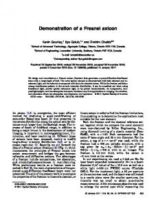
Fig. 3. (a) Schematic diagram of measurement setup for reflectance spectra. (b) Measured reflectance spectra of the logo “IME” on the central die of the wafer.
The display of RGB colors indicates that the lights with wavelengths corresponding to the three colors are resonant and reflected by the metasurface. In order to quantitatively analyze the performance of the metasurface, the reflectance spectra are measured. The experimental setup is shown in Fig. 3(a). The white light is launched into the optical system and focused on the sample by the objective lens (10 × objective lens with a numerical aperture of 0.25). The reflected light from the sample is collected by the objective lens and sent to the spectrometer. The spectrum of light reflected by a mirror is measured as the reference for normalization. The measured reflectance spectra of “I”, “M” and “E” are shown in Figs. 3(b)-3(d), respectively. As seen from Figs. 3(b) and 3(c), the letter “I” and “M” have the reflectance peak at wavelength of 675 nm and 570 nm, which contributes to the display of the red and green colors, respectively. Although there is no reflectance peak for letter “E” (Fig. 3(d)), the reflectance around 420 nm still gives rise to the blue color. The reflectance peaks of “I” and “M” slightly drift from the simulated values of 668 nm and 577 nm shown in Fig. 1(d). This may be caused by the refractive index of a-Si used in the simulation has difference with that of the fabricated a-Si. Besides, the fabrication error of a-Si pillar diameters also induces the reflectance peak shift from the designed value. One can also see the discrepancy of reflectance of “M” between the simulation and experimental results. It may be attributed to that the absorption coefficient of the fabricated a-Si is larger than the one used in simulation. And the small pillar diameter of “M” may have more defects in the fabricated sample and consequently results in the lower reflectance of the experiment result.
Vol. 26, No. 15 | 23 Jul 2018 | OPTICS EXPRESS 19553
4. Results and Discussion Table 1. Measurement results of wafer-level DICD. SEM show the photoresist nanopillars of letters “I” (red color), “M” (green color) and “E” (blue color), respectively. Color pattern Pitch (nm) Range (nm) 3Sigma(nm) SEM
“I” (Red)
“M” (Green)
“E” (Blue)
300 2.3 2.6
250 4.5 5.3
200 4.1 3.5
Fig. 4. Reflectance peak varying with the pillar’s diameter D for letter “I” (red color) and letter “M” (green color). Twelve dies along the horizontal and vertical midcourt line of the wafer are selected to measure both the spectrum and the diameter. The pitches of a-Si nanopillar arrays for letter “I” and letter “M” are 300 nm and 250 nm, respectively.
Since variations in the diameter of a-Si pillars deteriorates the performance of the metasurface, control of CD in the lithography and etching process is quite important. Table 1 shows the wafer-level map of the pillar diameters after lithography. As can be seen, the lithography has a good uniformity over the entire wafer in terms of the range (max - min) and 3Sigma values, which indicates that 193nm ArF immersion lithography is suitable for use in the mass production of nanostructure metasurfaces. For further analysis, final CD (after etch) and λR of a-Si pillars from 12 dies along the horizontal and vertical midcourt line of the wafer with the step of one die are measured and shown in Fig. 4. As λR of pillars for blue color is not located in the visible range as mentioned above, only that of red color and green color pillars are plotted. The CD of pillars for the red color ranges from 157 nm to 173 nm, with the corresponding λR ranging from 652 nm to 677 nm. The maximum variation in CD is ~7.65% referring to the designed value of 170 nm. The linearly fitting is used to analyze the relationship between λR and pillar diameter. As seen in Fig. 4, the changing slope of λR vs. D of pillars for the red color is around 1.3, close to the value of 1.4 calculated from the simulation results in Fig. 1(b). Similarly, the slope of pillars for the green color is 2.31, which is also with good agreement to the simulation value of 2.4 extracted from Fig. 1(b). The maximum variation in CD from the designed value of 120 nm is ~5.83%. The variations in CD are caused by the increase of etching rate from wafer center to edge area. The uniformity can be improved by optimizing the etching process. In fact, silicon is lossy in the visible
Vol. 26, No. 15 | 23 Jul 2018 | OPTICS EXPRESS 19554
region. Other dielectric materials with low absorption loss at visible range, like silicon nitride, titanium dioxide and aluminum nitride, are considered to demonstrate metasurfaces on 12 inch wafers in our future works. 5. Conclusion The a-Si metasurface for color display of RGB was demonstrated on a 12-inch wafer through the use of 193 nm ArF DUV immersion lithography and ICP etching process. The metasurface resonances at wavelength of 675 nm, 570 nm and 420 nm are experimentally observed in the reflectance spectra, resulting in the color display of letters “I”, “M” and “E” in red, green and blue, respectively. The uniformities of CD and spectral characteristics of 12 dies along the horizontal and vertical midcourt line of the wafer are analyzed. The data show that the maximum variation in CD is well controlled below ~7.65%. To the best of our knowledge, this is the first work to use CMOS technology for the fabrication of a dielectric metasurface on a 12-inch wafer with small CD as sub-hundred nanometer. It is a promising route to the mass production of dielectric metasurfaces for practical applications in flat optics. Funding RIE2020 Advanced Manufacturing And Engineering (AME) Domain's Core Funds — SERC Strategic Funds (A1818g0028).