Denoising and compression in wavelet domain via projection onto approximation coefficients Mario Mastriani
Abstract—We describe a new filtering approach in the wavelet domain for image denoising and compression, based on the projections of details subbands coefficients (resultants of the splitting procedure, typical in wavelet domain) onto the approximation subband coefficients (much less noisy). The new algorithm is called Projection Onto Approximation Coefficients (POAC). As a result of this approach, only the approximation subband coefficients and three scalars are stored and/or transmitted to the channel. Besides, with the elimination of the details subbands coefficients, we obtain a bigger compression rate. Experimental results demonstrate that our approach compares favorably to more typical methods of denoising and compression in wavelet domain.
Keywords—Compression, denoising, projections, wavelets. I. INTRODUCTION
A
image is affected by noise in its acquisition and processing. The denoising techniques are used to remove the additive noise while retaining as much as possible the important image features. In the recent years there has been an important amount of research on wavelet thresholding and threshold selection for images denoising [1]-[51], because wavelet provides an appropriate basis for separating noisy signal from the image signal. The motivation is that as the wavelet transform is good at energy compaction, the small coefficients are more likely due to noise and large coefficient due to important signal features [1]-[3]. These small coefficients can be thresholded without affecting the significant features of the image. N
In fact, the thresholding technique is the last approach based on wavelet theory to provide an enhanced approach for eliminating such noise source [4], [5] and ensure better image quality [6], [7]. Thresholding is a simple non-linear technique, which operates on one wavelet coefficient at a time. In its basic form, each coefficient is thresholded by comparing against threshold, if the coefficient is smaller than threshold, set to zero; otherwise it is kept or modified. Replacing the small noisy coefficients by zero and inverse wavelet transform on the result may lead to reconstruction with the essential Manuscript received January 1, 2008. The author is with the Departamento de Computación, de la Facultad de Ciencias Exactas y Naturales de la Universidad de Buenos Aires, Pabellón I, Intendente Güiraldes 2160, Ciudad Universitaria, (C1428EGA), Buenos Aires, Argentina. phone: +54-9-11-6504-8517; fax: +54-11-4576-3359; email:
[email protected].
signal characteristics and with less noise. Since the work of Donoho & Johnstone [3], there has been much research on finding thresholds, however few are specifically designed for images [14]-[51]. Unfortunately, this technique has the following disadvantages: 1) it depends on the correct election of the type of thresholding, e.g., OracleShrink, VisuShrink (soft-thresholding, hard-thresholding, and semi-soft-thresholding), Sure Shrink, Bayesian soft thresholding, Bayesian MMSE estimation, Thresholding Neural Network (TNN), due to Zhang, NormalShrink, , etc. [1]-[5], [8]-[38] 2) it depends on the correct estimation of the threshold which is arguably the most important design parameter, 3) it doesn't have a fine adjustment of the threshold after their calculation, 4) it should be applied at each level of decomposition, needing several levels, and 5) the specific distributions of the signal and noise may not be well matched at different scales. Therefore, a new method without these constraints will represent an upgrade. On the other hand, similar considerations should be kept in mind regarding the problem of image compression based on wavelet thresholding. The Bidimensional Discrete Wavelet Transform and the method to reduce noise and to compress by wavelet thresholding is outlined in Section II. The new approach as denoiser and compression tools in wavelet domain is outlined in Section III. In Section IV, we discuss briefly the more appropriate metrics for denoising and compression. In Section V, the experimental results using the proposed algorithm are presented. Finally, Section VI provides a conclusion of the paper. II. BIDIMENSIONAL DISCRETE WAVELET TRANSFORM The Bidimensional Discrete Wavelet Transform (DWT-2D) [6]-[7], [12]-[51] corresponds to multiresolution approximation expressions. In practice, mutiresolution analysis is carried out using 4 channel filter banks (for each level of decomposition) composed of a low-pass and a high-pass filter and each filter bank is then sampled at a half rate (1/2 down sampling) of the previous frequency. By repeating this procedure, it is possible to obtain wavelet transform of any order. The down sampling procedure keeps the scaling parameter constant
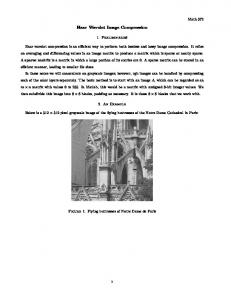
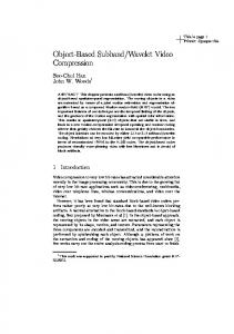
(equal to ½) throughout successive wavelet transforms so that is benefits for simple computer implementation. In the case of an image, the filtering is implemented in a separable way be filtering the lines and columns. Note that [6], [7] the DWT of an image consists of four frequency channels for each level of decomposition. For example, for i-level of decomposition we have: LL n,i: Noisy Coefficients of Approximation. LH n,i: Noisy Coefficients of Vertical Detail, HL n,i: Noisy Coefficients of Horizontal Detail, and HH n,i: Noisy Coefficients of Diagonal Detail. The LL part at each scale is decomposed recursively, as illustrated in Fig. 1 [6], [7]. Fig. 2 Two dimensional DWT. A decomposition step. Usual splitting of the subbands.
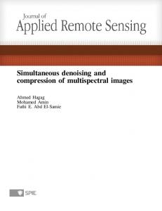
tion of noise is a difficult one. In fact, "one person's noise is another's signal". In part this depends on the resolution one is looking at. One algorithm to remove Gaussian white noise is summarized by D.L. Donoho and I.M. Johnstone [2], [3], and synthesized in Fig. 3.
Fig. 1 Data preparation of the image. Recursive decomposition of LL parts.
To achieve space-scale adaptive noise reduction, we need to prepare the 1-D coefficient data stream which contains the space-scale information of 2-D images. This is somewhat similar to the “zigzag” arrangement of the DCT (Discrete Cosine Transform) coefficients in image coding applications [42]. In this data preparation step, the DWT-2D coefficients are rearranged as a 1-D coefficient series in spatial order so that the adjacent samples represent the same local areas in the original image [44]. Figure 2 shows the interior of the DWT-2D with the four subbands of the transformed image [51], which will be used in Fig.3. Each output of Fig. 2 represents a subband of splitting process of the 2-D coefficient matrix corresponding to Fig. 1. A. Wavelet Noise Thresholding The wavelet coefficients calculated by a wavelet transform represent change in the image at a particular resolution. By looking at the image in various resolutions it should be possible to filter out noise, at least in theory. However, the defini-
Fig. 3 Thresholding Techniques
The algorithm is: 1) Calculate a wavelet transform and order the coefficients by increasing frequency. This will result in an array containing the image average plus a set of coefficients of length 1, 2, 4, 8, etc. The noise threshold will be calculated on the highest frequency coefficient spectrum (this is the largest spectrum). 2) Calculate the median absolute deviation (mad) on the largest coefficient spectrum. The median is calculated from the absolute value of the coefficients. The equation for the median absolute deviation is shown below:
δ mad =
median(| C n ,i |)
(1)
0.6745
is greater than the threshold. This moves the image coefficients toward zero.
where Cn,i may be LHn,i , HLn,i , or HHn,i for i-level of decomposition. The factor 0.6745 in the denominator rescales the numerator so that δ mad is also a suitable estimator for the standard deviation for Gaussian white noise [5], [42], [44]. 3) For calculating the noise threshold λ we have used a modified version of the equation that has been discussed in papers by D.L. Donoho and I.M. Johnstone. The equation is:
λ = δ mad 2log[N ]
(2) Fig. 4(b): Hard-Thresholfing
where N is the number of pixels in the subimage, i.e., HL, LH or HH. 4) Apply a thresholding algorithm to the coefficients. There are two popular versions: 4.1. Hard thresholding. Hard thresholding sets any coefficient less than or equal to the threshold to zero, see Fig. 4(a).
The respective code is: for row = 1:N1/2 for column = 1:N1/2 if |Cn,i[row][column]|