Based on the premise that uniformly dense beacon placement is not practical, we moti-vate the need for adaptive ... Facebook · Twitter · Reddit · Bibsonomy ...
Density Adaptive Algorithms for Beacon Placement in Wireless Sensor Networks Nirupama Bulusu UCLA
John Heidemann USC/ISI
an important building block for such systems. Many of these envisioned systems are embedded to monitor or control the behavior of physical systems (as compared with strictly virtual information systems), and therefore nodes often need to determine their action based on their physical location (am I the right sensor to monitor a particular object?). Localization is indispensable for contextaware applications that select services based on location [14], and for sensor networks that achieve power conservation by combining data from multiple sensors. Moreover, localization information on a scale with transmission range can enable geographic routing algorithms that can propagate information efficiently through a multihop network [23]. Traditional information systems have not had to have such a location focus. Existing geolocation systems such as GPS [16] do not always meet the operational (for example, low power), environmental (for example, indoors) or cost constraints. Consequently, the spatial localization problem has received a lot of attention in the past few years, with several systems proposed both in the context of outdoor environments [2, 7, 25] and indoor environments [36, 30, 37, 1, 6]. The goal of some of these systems is for nodes to cooperatively form a completely self-contained spatial coordinate system [28, 10, 6], independent of actual node position on the geoid or relative to any external point. However, the design of a large number of these systems ([2, 7, 36, 30, 37, 1]) is based on an infrastructure of beacons, wherein some fraction of the system nodes that know their position (for example through GPS in the outdoor context or manual configuration in the indoor context) serve as beacons, while the other nodes estimate their location by communicating with beacons either by ranging or proximity methods. This idea has been espoused by many researchers including [2, 7, 27], especially in the context of methods that estimate location from RF-connectivity. This fits in well with general sensor network architectures, wherein, to accommodate small form factor considerations, a tiered architecture is proposed that trades form factor and power considerations at the lowest level for functionality and flexibility at the highest level [4]. As we argue later in this paper, the placement of beacons strongly affects the quality of localization in a system. Researchers often [30, 36] refer to beacon placement as a non-trivial factor in the design of any localization system but have only rarely addressed it. There is a simple reason for this. Much of their attention thus far has focused on building and demonstrating a proof-of-concept spatial localization system. In this paper, we address this void, by focusing on beacon placement. We also emphasize the interesting nature of the problem as a case study to make systems self configuring. Our design goals are as follows:
Abstract
Spatial localization is an important building block for wireless sensor networks. Beacons that know their position and serve as reference are a vital aspect of nearly every localization system. In this paper, we look at beacon placement, which has a significant impact on the overall quality of localization. Based on the premise that uniformly dense beacon placement is not practical, we motivate the need for adaptive beacon placement in both medium and dense sensor networks. We use the notion of solution space density described in the paper to motivate different approaches to beacon placement for different regimes of beacon deployment density. Thus, we propose the HEAP incremental beacon placement algorithms applicable to low density regimes of beacon deployment and the STROBE adaptive density algorithms applicable to high density regimes of beacon deployment. Distributed placement algorithms like HEAP can do as well as centralized algorithms, with maximum gains at lower densities, even though they have incomplete knowledge. Adaptive algorithms like STROBE can extend dense lifetimes by 1.5 times compared to leaving the beacons on always (for deployment density 3 times the saturation density), with higher lifetime gains obtained at higher densities. This paper provides a case study of how density interacts with two adaptive, selfconfiguring algorithms, and develops a methodology and intuition that will be useful in addressing the increasing number of other problems adapting algorithms to dense node deployment. 1
Deborah Estrin USC/ISI and UCLA
Introduction
Recent advances in miniaturization and low-cost, low-power design have led to active research in large-scale, highly distributed systems of small, wireless, low-power, unattended sensors and actuators [8, 20, 29] or wireless sensor networks. Wireless sensor networks will enable fine-grained observation and control of the physical world. The vision of many researchers is to create sensorrich smart environments through planned or ad-hoc deployment of thousands of sensor nodes, each with a short-range wireless communications channel, and capable of detecting ambient conditions such as temperature, movement, light, acoustic events or the presence of certain objects. Spatial localization, or the ability of a node to locate itself is
� 1
Empirical adaptation: We argue that because of the vagaries
of radio propagation and environmental conditions, beacon placement cannot be preconfigured and needs to be empirically adaptive. Adaptation refers to improving the quality of localization by adjusting beacon placement or adding a few beacons rather than by completely re-deploying all beacons. Empirical refers to an adaptation influenced by measurements of the operating localization system rather than by careful or complete off-line analysis of a complete system model.
�
�
and we expect that the ideas and methodology developed in this paper will be more broadly applicable. For example, adaptive, self configuring algorithms applied to distributed topology control in the wireless context [4] and energy conserving ad hoc routing. A central problem to many kinds of algorithms in the post-PC computing era is how to make use of thousands of devices in a small area, and what role density plays. This question comes up in many problems: localization, energy conserving ad hoc routing, beam forming, collaborative signal processing or sensing, MEMS on airfoils, etc. What density is required to accomplish the given task. How should nodes cooperate to achieve that density? This paper provides a case study of how density interacts with two algorithms, and develops a methodology and intuition that will be applicable for other similar problems.
Self configuration: Ad hoc sensor networks consist of nodes strewn arbitrarily in the environment and will be largely unattended. Such unattended networks must self configure and reconfigure to adapt to the particulars of their environmental setting and the availability of other beacons in the system. Localized algorithms: Localized algorithms refer to a distributed computation in which nodes only communicate with nodes within some neighborhood, yet achieve a desired global objective. Scaling and robustness considerations and the physically distributed nature of sensor networks imply that beacon placement is better addressed through localized algorithms [8], because communicating and updating dynamic information globally will excessively drain energy resources of the system.
2
Related Work
In this section, we examine sources of localization error in these systems, discuss various methods used to reduce localization error, specifically beacon placement, explain our intuition as to why empirically adaptive beacon placement is superior to fixed beacon placement and outline some of these approaches. 2.1
The basis for the work presented in this paper is the notion of solution space density. The efficacy of algorithms (such as our beacon placement algorithms) designed to work in noisy environments is predicated on the assumption that the solution space for the problem must be dense in the number of satisfying solutions. For instance, if the only way to improve the quality of localization in a region by adding an additional beacon is to place it at a specific point in the region, then it is difficult to design algorithms that can identify that point in the presence of so much noise. Thus, the objective of our beacon placement algorithms is not to identify the optimum points for placing additional beacons but to identify good candidate points. Not surprisingly, the solution space density of such candidate points decreases as the number of beacons in a region or the beacon deployment density increases. Our observations on solution space density lead us to propose two different classes of algorithms for low and high beacon deployment density regimes respectively. Specifically, the contributions of this paper are as follows:
Localization
For a much higher density regime of operation, we propose the STROBE algorithms that selectively turn off some beacons so as to balance the twin goals of extending system lifetime and maintaining uniform localization granularity. We also propose a simple deterministic energy usage model, that allows us to set guidelines for the various STROBE parameters as well as evaluate the applicability of STROBE in various contexts. The lifetime gains with STROBE increase with an increase in deployment density.
In the past few years, various localization systems have been proposed and discussed in detail (for example, in [2]). These include but are not limited to: systems based on RF Time Difference of Arrival techniques [16, 37, 6], systems based on ranging using RF and sound [36, 30], cameras [22] and video [32] based on triangulation of images, systems based on measurements of RF signal strength [1, 15, 26] and proximity based approaches [2, 7, 28] which use measurements of RF connectivity. The approaches employed in these systems usually fall under one of two broad categories: proximity based approaches (position estimation from proximity information to one or more beacons or nodes) and multilateration (position estimation from distances to three or more known points) based approaches. Localization error in these systems stems from various sources. The most serious source of localization error is beacon unavailability, which may be caused both by insufficient beacon deployment density, and by RF propagation unpredictabilities such as multipath1 , dead spots, fading and obstruction [31] that affect the visibility of beacons that should be in range. Proximity based approaches are particularly sensitive to RF propagation unpredictability. The second kind of errors are measurement errors, that vary depending on the ranging technology used, precision of time synchronization and the quality of equipment, but generally fall into two categories: unpredictable measurement errors that generally follow a Gaussian distribution and can be dealt with, and errors resulting from local properties of the environment, and do not follow the same Gaussian distribution. These are typically caused when there is no direct line of sight to beacons, a common situation in many environments. Non line of sight error is also generally the most difficult to deal with [11]. The third source of error arises due to beacon placement and geometry. In ranging systems, distances determined by receivers have an associated uncertainty. Information from one beacon will therefore place the receiver somewhere in a shell of points whose thickness is equal to the range uncertainty surrounding the beacons. The shape of the locus of possible estimates of the receivers position in the plane is affected by the relative geometry of the beacons and the receiver. Thus, the best case for location information from 3 beacons is when the beacons are located in an equilateral triangle, the worst case is when the three beacons are
Although we evaluate our algorithms in the context of beacon placement, the problem of adapting to node density is much broader
1 This applies to narrow-band sinusoidal RF communications technology. Ultrawideband (non-sinusoidal) technology has better multi-path properties.
� �
�
We discuss the role of beacon placement in reducing localization error and explore various approaches to addressing the problem. For a low density regime of operation and somewhat benign conditions, we propose the HEAP algorithms for incremental deployment of additional beacons, wherein, existing beacons exchange neighborhood information to determine candidate points where new beacons could be added. The incremental gains obtained with HEAP decrease with an increase in density.
2
too close (collinear and almost the same point). In proximity based schemes such as [2, 7], the placement and density of beacons essentially controls the granularity of localization. Researchers have used two approaches to reduce localization error in their systems. The first is to combine simple geometric consistency checks and statistical tests to identify and eliminate incorrect distance measurements, used in [36, 30]. Other examples are the use of Kalman filters in RADAR [1] and hill-climbing algorithms in SpotON [15]. Although such statistical techniques can alleviate some problems, they cannot completely eliminate the non LOS problem. The second is multi-modal localization, a roboticsinspired approach proposed in [11], of using multiple but orthogonal sensing modalities (for example, acoustic and optical ranging) to eliminate spurious non Line Of Sight readings. While this is a very powerful concept, it is applicable only to some environments, and to nodes that are sophisticated enough to accommodate multiple modalities, as opposed to end nodes which rely solely on RF characteristics to learn their location. 2.2
pute an ideal (or even satisfying) beacon placement that uniformly achieves the desired quality of localization across the region. The premise of our work is that, the beacon placement needs to adapt to the noisy and unpredictable environmental conditions. 2.2.2
Because of the various reasons explored above, we believe that beacon placement needs to be empirically adaptive. Empirical adaptation has served as a powerful design principle for various networking protocols, including TCP[18], SRM[9], and measurement based admission control [19]. Bulusu et al., [3] have proposed and evaluated two simple RFproximity algorithms for incremental beacon placement based on autonomous exploration and instrumentation of the terrain by a mobile human or robot agent. Both algorithms make measurements of localization error at various points on the terrain (with a differential GPS equipped mobile agent). The MAX algorithm essentially picks the point with maximum error, whereas GRID subdivides the terrain into several overlapping square grids, computes cumulative localization error over each grid and places beacons at the selected grid center with the highest cumulative error. In their evaluation, they found that the algorithms were appplicable to low density regimes of operation in ideal conditions, and moderate density regimes with noise. In general, GRID performed much better than MAX. This paper addresses one big drawback with their approach: It is not applicable to situations where it may not be possible to physically measure error at arbitrary positions. Moreover such an approach does not scale very well for large terrains. These scaling and accessibility considerations motivate the work presented in this paper. The focus of this paper is the design of beacon placement algorithms based on two complementary distributed and adaptive approaches.
Beacon Placement
As we have described above, a significant component of localization error arises due to beacon locations. Addressing beacon placement complements many of the other techniques proposed to address localization error. 2.2.1
Empirically adaptive beacon placement
Fixed beacon placement
Several simple beacon placement approaches appear feasible in theory, including uniform placement and dense deployment. Unfortunately they are infeasible in practice. Uniform placement is good as a starting point but is insufficient because (a) noise in the form of terrain and propagation uncertainties may affect the reachability of beacons that should be in range and (b) beacons may be perturbed during deployment or fail post-deployment. Very dense placement by itself is not a viable solution because of cost or power considerations, combined with terrain commonalities and the possibility of self-interference through collisions amongst beacons. Other researchers have proposed guidelines based on knowledge of environment conditions and application requirements or optimal approaches to placement. Active Bat [36] proposes using ceiling mounted beacons to maximize likelihood of Line Of Sight to beacons. The Cricket Location Support System [30], which is also proximity based, proposes deployment guidelines for beacons in indoor environments based on similarly practical considerations. Doherty et al. [7] propose placing known nodes (beacons) on the perimeter of the network, especially at the corners, for best results with their convex position estimation based on global knowledge of connectivity constraints of all known and unknown nodes. While guidelines work well for a specific localization method [7] or environmental setting [30, 36], they are not generalizable to a variety of environments and systems. They are especially not applicable to large scale ad hoc sensor network deployments and problems caused by unknown and unpredictable RF propagation. Optimal placement problems have been studied in various contexts by researchers including facility location problems in theory [5] and pursuit evasion problems in robotics [12]. Potkonjak et al., [33] have proposed solutions to coverage problems in wireless ad hoc sensor networks given global knowledge of node positions using Voronoi diagrams to compute maximal breach paths and find gaps. Again these algorithms do not take into account terrain and radio propagation conditions and are essentially centralized. The fundamental limitation of these fixed approaches is that they do not take into account the environmental conditions when they cannot be predicted a priori. It is virtually impossible to preconfigure to such terrain and propagation uncertainties and com-
�
�
Simulated local exploration by beacons: An approach alternative to actual terrain exploration is for beacons to collect information about other beacons in their immediate neighborhood and use that to simulate error in the terrain and discover problems. Adaptive Operational Density: As we have argued, having a very high density alone will not guarantee better localization quality. This is because localization using strictly local information essentially saturates for a certain beacon density,as we explore later in this paper. Consequently, we explore an approach, wherein, given high density beacon deployment nodes adaptively adjust their duty cycle based on availability of other beacons.2
We describe our algorithms in the context of an RF-localization system described in [2]. In their system, a receiver node located at (Xa ; Ya ) localizes itself to the centroid of the k beacons to which it has connectivity: � � (Xest ; Yest ) = Xi1 + + Xik ; Yi1 + + Yik
��� k
��� k
2 This is similar but not identical to adaptive fidelity [8]. The difference is that beacons in adaptive density algorithms do not sacrifice fidelity (granularity), but only selectively turn themselves off if they know it will not affect the granularity. The principle behind adaptive fidelity, articulated by Estrin et al., [8] is that the fidelity of the system can be traded for battery lifetime, system responsiveness etc. Within the context of unattended ad hoc sensor networks, adaptive fidelity can be applied to several problems, including energy-conserving ad hoc routing Xu et al.,[38]. The GAF algorithm proposed by them adapts sleep times based on node density, scaling back node duty cycles (and so reducing routing “fidelity”) when many interchangeable nodes are present. This allows it to substantially increase the network lifetime.
3
We later argue that our adaptive operational density approach, applies more generally to other kinds of RF-based localization approaches as well. We face several challenges in designing these algorithms. First, these algorithms must scale to several thousands of beacons in the beacon field. Second, beacons may fail, may lose battery power, or may be temporarily unable to communicate due to environmental factors. The algorithms must be robust to such failures. Finally, wireless communications even over relatively short distances consumes significant energy. The algorithms must minimize energy usage. In the next two sections, we describe our techniques and present results of simulation studies of our algorithms. 3
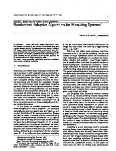
Beacon Node Central Site
HEAP algorithms for Incremental Beacon Deployment
Figure 1: Data dissemination for the HEAP Algorithms
Given a localization algorithm, one must deploy a field of beacons as infrastructure and then extend this field if it proves insufficient. Our approach to incremental improvement of localization through beacon placement is based on empirical adaptation, described in Section 1. Our general approach is for beacons to exchange information about their neighboring beacons. Based on this information, beacons evaluate a suitable candidate point in their immediate neighborhood (for example, a region of radius r around the beacon) for adding a beacon. Eventually, the candidate points selected by beacons must be sent to a central control site, which must decide from amongst various candidate points where to deploy new beacon nodes. There are many possible models for such a system. In this work, we consider systems where the control site is fixed and located far from the beacons. All beacons in the network are homogeneous and energy constrained. In such systems, short-range hop-by-hop communication is preferred over direct long range communication to the destination site. Coincidentally, such hop-by-hop communication also provides a form of communication diversity in helping communicate around obstacles [29]. Energy efficiency also implies that it is infeasible to transmit all data across the network, even hop-byhop. As Pottie and Kaiser [29] show, performing local computation to reduce data before transmission can obtain orders of magnitude energy savings. This motivates us to adopt a hierarchical (or heap based) approach, in which, the wireless sensor network consists of three entities: Node, Beacon and a Central Site. Nodes aggregate and relay data from the beacons to the central site hop by hop. This is illustrated in Figure 1. Note that HEAP is really a distributed algorithm. It depends on processing in the network to select placement sites; the central site is required because we assume incremental node deployment from a single agency (we selected this definition for comparison with prior central algorithms [3]). A fully distributed variation on the HEAP algorithm would allow an aggregation node to deploy additional beacons if improvement passed some threshold. Since the possible design space of such algorithms is large, we state our assumptions. We assume a low density regime of beacon deployment. We also assume that beacons are static during the lifetime of the system and can be distinguished from other nodes with respect to functionality. To simplify our exposition, we use the following terms. Beacon deployment density is the number of beacons per unit area. Coverage area is the total area in the terrain that is covered by at least one beacon.Beacons per neighborhood (also referred to as beacons per nominal radio coverage area bpnrca) is the number of beacons that exist in a nominal radio transmission coverage area of � Range2 .
3.1
Algorithms
Once the mechanism for data dissemination is in place, the three entities Beacon, Node and Central Site execute the following procedures respectively: Procedure at Beacon B : A beacon node exchanges information and learns where other beacons in its neighborhood are located. It then selects a candidate point and sends it to its parent node. Procedure at Node N : An intermediate node in the hierarchy receives candidate points from all its neighboring beacons and child nodes, selects and forwards one candidate point to its parent node. Procedure at Central Site C : The central node in the hierarchy receives candidate points from all its neighboring beacons and child nodes, eliminates any candidate points that do not satisfy constraints and selects good points for addding new beacons. This can be described in the following steps: Before the HEAP algorithms can select a candidate point, they need to estimate their beacon neighborhood to the appropriate number of hops, determined by the details of the algorithm. This is accomplished using the following algorithm: Procedure BEACON NEIGHBORHOOD(NumHops ) at Beacon B : In this procedure, beacons include their neighborhood information of other beacons up to a certain scope in their advertisements, iterating NumHops times, increasing their scope each time. Step 0 The process consists of NumHops phases. Phase 1 scope = 0. BROADCAST(B, scope, position(B)) and listen to broadcasts of other beacons positions. Neighborhood(1) (or the 1-hop neighborhood) is the set of all the beacons heard during this period. Phase NumHops scope = NumHops 1. BROADCAST(B, scope, Neighborhood(NumHops - 1)) and listen to broadcasts of other beacons NumHops 1 neighborhoods. Neighborhood(NumHops) is the union of all the NumHops 1 neighborhoods heard during this period. We consider two simple algorithms for selecting candidate points, namely HEAP-MAX and HEAP-GRID. These algorithms extend the basic GRID and MAX algorithms proposed in [3] to the case where only limited local knowledge is available. The goal of these algorithms is to determine candidate points for placement of an additional beacon, so as to maximize the gains obtained. These algorithms essentially differ in the amount of local knowledge they require. Algorithm HEAP-MAX: The HEAP-MAX algorithm learns the neighborhood of a beacon, simulates localization error at several
�
4
BEACON NEIGHBORHOOD(4)
Step 0 NeighborSet
Steps 1, 2 and 3 are the same as the HEAP-MAX algorithm, except side = 3 Range
�
Step 4 Divide the square region into NG partially overlapping grids as follows: Range
B
�
Step 4.1 Each grid has a side, gridSide = 2 Range. Thus each grid encloses the radio reachability region of its center. Step 4.2 For 1 i; j NG , the grid G(i; j ) is defined by its center gridSide) ; gridSide + Gc (i; j ) = ( gridSide + (i 1)�(Side 2 2 NG 1 (j 1)�(Side gridSide) ) NG 1
side = 2. Range
�
�p
p
p
Step
Step 5 For each grid G(i; j ), compute the cumulative localization error S (i; j ) at all the points measured in Step 3 that lie in the grid G(i; j ).
Figure 2: Illustration of the HEAP-MAX algorithm at each node. G(5,5)
Step 6 Return (Gc (i; j ); S (i; j )) of the grid G(i; j ) with the maximum cumulative localization error.
We next discuss the details of the HEAP algorithm and provide a performance evaluation of these algorithms. We note that these are by no means the only possible algorithms, but are representative of the effectiveness attainable with different degrees of processing and local knowledge.
G(2,2)
G(1,1)
Range
Gc(2,2)
B
side=3.Range
Gc(1,1)
GridSide =2.Range
R 3.2
HEAP Algorithm Details
Neighborhood estimation
The design of HEAP is predicated on the assumption that local knowledge to a certain degree rather than complete global knowledge is relevant to a beacon. For instance, an important aspect of Figure 3: Illustration of the HEAP-GRID algorithm at each node. HEAP is neighborhood estimation. In order to select a candidate point in its immediate neighborhood, each beacon needs to know whether and where other beacons exist in its neighborhood. For uniformly separated points in its neighborhood, and selects the point instance, the HEAP-MAX algorithm selects a candidate point in with the highest error as a candidate point. This is illustrated in Figa region of radius Range around it (see Figure 2). To make this ure 2. The HEAP-MAX algorithm can be described in four steps: selection, it simulates the localization error at each point at a disStep 0 NeighborSet BEACON NEIGHBORHOOD(3) tance less than or equal to Range from it. For this, it needs to at least know all the beacons that are in radius 2 Range around it Step 1 Consider a square region of side=2 Range centered at (assuming ideal propagation conditions). How many hops should position(B ) = (Bx ; By ). it exchange neighborhood estimates to learn this information? We define the K -hop neighborhood of a beacon node to be the set of Step 2 Divide the square region into step step squares. all beacons that are reachable from the beacon in K hops and the Step 3 Simulate localization error at each point P (Bx side=2+ L-Range neighborhood of a beacon node to be the set of all beai step; By side=2 + j step) in the in the region that cons that are within distance L Range. The probability that the 2�Range L Range neighborhood is a subset of its L +1-hop neighborhood corresponds to a square corner. (0 i; j step ) P is assumed to be able to hear from all the beacons in NeighborSetdecreases with the beacon density and L. From simulations, we found that for the beacon densities and ranges we consider in this that are within distance Range of P . Location estimate of P section of the paper, the probability is around 0.72 for L = 2 and is computed as the centroid of all these beacons.3 . around 0.67 for L = 3. Furthermore, a majority of the mismatches Step 4 Return ((Xm ; Ym ); error) the point that has the highest involved just one beacon. Thus, we select 3-hop neighborhood essimulated localization error. timation for HEAP-MAX and 4-hop neighborhood estimation for HEAP-GRID. Algorithm HEAP-GRID: The HEAP-GRID algorithm, illustrated in Figure 3, also learns the neighborhood of a beacon, but with a Undetected coverage larger scope. Its approach is to simulate the cumulative localization error over each grid for several uniformly separated points in its Another aspect of the HEAP algorithms is that only those parts neighborhood, divides the neighborhood into a few square grids, of the terrain that fall in a beacon’s immediate neighborhood are and picks the grid center with the highest error as a candidate point. instrumented. Some part of the terrain that is uncovered may be This is based on the observation that adding a new beacon affects its undetected. We believe that our algorithm will envelope holes i.e., nearby area, not just the point where it is placed. The HEAP-GRID pick candidate points close to the boundary of these holes. By placalgorithm can be described in six steps: ing multiple such beacons at a hole boundary, these holes may be Step
�
�
�
�
�
�
�
�
3 A more general approach for such computation is given in [7]
filled in. 5
�
Boundary conditions
Table 1: Terrain-influenced Shadowing Model Parameters Parameter Value � 0.333 1 2 2 4 �dB 5 Pt 660mW
For connectivity based schemes, localization error tends to be the highest at the terrain boundary where the density of beacons tends to be lower. Specifically the largest error is near the four corners of the terrain. Thus algorithms such as HEAP which tend to quantitatively evaluate error may select these points. There are a few simple solutions to this problem: (i) Deploy beacons so that their convex hull encloses the terrain of interest and do not consider points beyond the convex hull of beacons. (ii) Use a simple filter at the central site to discard candidate points near the corners of the terrain. (iii) Edge detection by the beacons so that the beacons at the boundary learn this and use it to suppress their candidate points. 3.3
reflects the variation of the received power at certain distance. The overall shadowing model is represented by � � � � Pr (d0 ) (1) = 10 log dd + XdB 0 Pr (d) dB
Evaluation of HEAP algorithms
We report on some results from a preliminary performance evaluation of our beacon placement algorithms. We use numeric simulations to explore, in some detail, the implications of several design choices. 3.3.1
where is called the path loss exponent. Typically = 2 for free space propagation, and lies between 3-5 for outdoor obstructed environments [31]. Pr (d0 ) can be computed from the Friis free space model [31]. XdB is a Gaussian random variable with zero mean and standard deviation �dB . �dB is called the shadowing deviation. Its typical value in outdoor environments is 5-12. The shadowing model extends the ideal circle model to a richer statistical model: beacons can only probabilistically communicate when near the edge of communication range or when there is clutter in between. The terrain-influenced shadowing model extends the shadowing model in cluttered environments to a terrain based model. By inspecting a bitmap of the terrain, it distinguishes the case when there is clear line-of-sight between two points (good propagation condition) and when there is not (bad propagation condition). Radio propagation conditions can be varied by choosing different path loss exponents ( 1 for good propagation and 2 for bad propagation respectively), to simulate the significant difference in signal strength and multi-path effects between direct and indirect transmission. The communication range is decided by the transmission power, propagation condition and the receiving threshold. The experiments were carried out in a simulated square terrain of side 100m. From Figure 5 we can see that the environment contains both obstructions and good terrain, so the terrain based propagation model is quite appropriate. The various propagation model parameters we chose is summarized in Table 1. The values of and �dB are chosen from the ranges of their typical values [31]. Pt , the transmit power is selected from [21] and Pthresh , the receiving threshold is set to be the receive power at the nominal radio range Range using Friis free space model [31]. These do not necessarily reflect the details of real environment but are representative of a range of environments in which our algorithms may be used.
Simulation Methodology
Our goals in conducting this evaluation were two-fold:
�
�
Compare the performance of the HEAP-MAX and the HEAPGRID algorithms to a completely Random algorithm as well as to centralized algorithms (GRID, MAX) with global knowledge of beacon positions and terrain or connectivity conditions. Understand the impact of noise such as propagation losses and terrain features on the beacon placement algorithms.
We choose the following metrics to analyze and compare the performance of our algorithms. These metrics are statistics evaluated for the observed localization error at all step step square corners obtained by subdividing the region. Improvement in mean error computes the difference between mean localization error at all measured points in the terrain before and after the beacon node is added. This metric indicates the overall impact of adding a beacon to quality of localization in the entire terrain. Improvement in median error computes the difference between the median localization error at all the measured points in the terrain before and after the beacon node is added. This metric indicates the improvement due to adding a beacon on the quality of localization at the top 50% of the points with the highest localization error at the terrain. We study these metrics as a function of beacon density. In addition, we assume step = 1m. The mean and median localization error metrics can also be evaluated over initial and final coverage areas, for instance.
�
3.3.2
Simulation Results
In our first simulation experiment, each beacon has a nominal radio transmission range of 15m. We vary the number of beacons from 20 to 80 nodes in increments of 20 beacons. The corresponding beacon density varies from 0.002 beacons per square m to 0.008 beacons per sq. m. To put these density values in context, the corresponding number of beacons per nominal radio coverage area (bpnrca) or beacons per neighborhood varies from 1.41 to 5.64. For each density, we generate 1000 different beacon fields. Each beacon field is generated by randomly placing the beacons in the 100m 100m square terrain. The performance metrics, for each algorithm and beacon density, are averaged over the 1000 beacon fields. To characterize the stability of our results, all graphs include 95% confidence intervals. The goal of our first simulation experiment is to compare the performance of our localized HEAP algorithms with centralized
Radio Propagation models
In order to evaluate our HEAP algorithms under different propagation conditions, we carried out our simulations both for (i) ideal radio propagation conditions and (ii) a terrain based shadowing model based on a bitmap of the environment. We have ported the latter from Arena/ns [39] to our simulations and describe it below. Terrain-influenced Shadowing Model: The basic log-normal shadowing model [31] consists of two parts. The first is a path loss model which predicts the mean received power at distance d, denoted by Pr (d) relative to a close-in reference distance d0 . The second is a log-normal random variable4 that
�
4 It is of Gaussian distribution if measured in dB.
6
Heap-Max (Ideal)
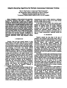
measurement based algorithms, GRID and MAX, described in [3]. HEAP-GRID and HEAP-MAX are derivatives of GRID and MAX respectively. Figure 4 plots the improvements in the mean and median localization errors as a function of beacon deployment density for both ideal radio propagation model and the terrain based shadowing model. Ideal Radio Propagation: For the ideal case, the first metric we consider is the improvement in mean localization error in the terrain. All the algorithms perform well for low densities (< 3 bpnrca), but GRID has the potential for significant improvements. The improvements to mean localization error from the GRID class algorithms fall more rapidly than the MAX class of algorithms for densities 3 bpnrca. At these densities the points with maximum localization error are very prominent, and the MAX algorithms suppress them better. A slightly different trend is observed with respect to improvements in the median localization error when the HEAP algorithms are compared to the centralized algorithms. For low densities the median error improvement relative to MAX is the same for HEAPMAX and much better HEAP-GRID algorithm. Furthermore, the gains in median localization error for GRID relative to HEAPGRID are much lower in comparison to the mean error improvement. For higher densities, MAX and HEAP-MAX have better gains in median error improvement when compared to GRID and HEAP-GRID respectively. It is not surprising that HEAP fares much better with the median localization error metric than the mean relative to the centralized algorithms. Because the HEAP algorithms select candidate points only in their neighborhood, they are less likely to pick up noisy points as well as the centralized algorithms. Their worst case improvements, and by extension, the mean improvements tend to be much smaller. Terrain based Shadowing Model: The trend exhibited in the ideal case with respect to median error is further exemplified for the terrain case, as Figure 4 shows. In the terrain case, for low densities, the total number of noisy points far exceeds the ideal case. GRID and MAX which instrument the whole terrain leverage this and post higher gains in mean error by substantially improving a large number of bad points. HEAP-GRID and HEAP-MAX focus on moderately bad points and thus the improvement is relatively lower. The median error improvements for the terrain case for the HEAP algorithms are also much better for higher densities. Although the gains for HEAP do not equal the centralized algorithms, they are comparable. Moreover, the HEAP algorithms are distributed and therefore much more scalable. Impact of terrain features:The goal of our second simulation experiment is both to understand the impact of terrain features and to qualitatively evaluate the efficacy of our HEAP algorithms in selecting good candidate points. In this experiment, for uniform placement with 25, 36, 49, 64, 81 and 100 nodes and with nominal radio propagation ranges set to 15m, 20m, and 25m, we apply the HEAP algorithms to select candidate points for (a) an ideal terrain with no obstacles and (b) a terrain with a wall in the middle shown in Figure 5. In Figure 5, each point represents a placed beacon from one simulation run. The lower two plots add a wall (shown in grey) as terrain; the upper two are open. The left two plots show the HEAP-MAX algorithm, the right, HEAP-GRID. For both cases, a simple boundary constraint is applied to remove algorithm bias towards candidate points at the corners of the terrain. In the ideal case, HEAP-GRID selects candidate points closer to the periphery of the region enclosed by the boundary constraint. There is a reason for this: HEAP-GRID places candidate points at the center of a grid with highest cumulative localization error. In the ideal case, such grids are more likely to be located at the edges of the terrain (even with uniform beacon placement). Using the
Heap-Grid (Ideal)
100
100
80
80
60
60
40
40
20
20
0
0 0
20
40
60
80
100
0
20
Heap-Max (Terrain)
�
40
60
80
100
80
100
Heap-Grid (Terrain)
100
100
80
80
60
60
40
40
20
20
0
0 0
20
40
60
80
100
0
20
40
60
Figure 5: Candidate points selected by the HEAP algorithms under uniform placement for the ideal case and for a terrain with a wall in the middle. Candidate points shift closer to the center when there is a wall in the middle. boundary constraint, grid centers satisfying the boundary constraint but with high cumulative error will be selected. These are most likely to be found near the periphery. HEAP-MAX which chooses candidate points based on highest error at individual points, selects points uniformly in the region enclosed by the boundary constraint. The actual points selected depends on the nominal beacon transmission range and where beacons are actually located. For a terrain with a wall in the middle, the candidate points shift closer to the center with both algorithms. The actual points chosen depend on the beacon density, range and positions of the beacons relative to the wall. The deviation from the center for the candidates chosen by HEAP-MAX is lower than for HEAP-GRID. With HEAP-MAX, the maximum offset is less than 25m, the maximum range. The offsets are higher for HEAP-GRID because of the way it chooses candidate points. It selects the center of the grid with the highest cumulative error, rather than the points in the grid that have the highest error. This is an important and interesting result for the following reasons: The HEAP algorithms have only a very approximate knowledge of their neighborhood using only local coordination. The HEAP algorithms use an idealized radio model for a simulated exploration and to select the candidate points. In the centroid based localization approach, error at a point is a function of beacon density, placement as well as the actual position of the point. Despite the interplay between various sources of error, the HEAP algorithms are able to select candidate points closer to a terrain feature such as a wall. How does this happen? Once again, we express our argument in terms of solution space density. A large object like a wall affects several points, thereby making it easier to detect these points. Our result supports our hypothesis that when the solution space density is high, localized, empirically adaptive algorithms can be applied effectively. However, such a result may not be valid for very small terrain objects, such as foliage. There are two general lessons that can be drawn from our preliminary design and evaluation of HEAP:
� 7
Distributed algorithms using only limited local knowledge and coordination such as HEAP can perform very effectively
Side=100m, Range=15m, Terrain Beacons per neighborhood 0
1
2
3
4
Side=100m, Range=15m, Terrain Beacons per neighborhood
5
6
7
0
2.5
1
2
3
4
5
6
7
0.6
Improvement in median error (m)
Improvement in mean error (m)
Grid
Grid 2
1.5
1 Heap-Grid Max 0.5 Heap-Max Random 0
0.5
0.4 Heap-Grid
0.3 Max Heap-Max
0.2 Random 0.1
0 0
20
40
60
80
100
0
20
Beacon deployment density (per 10000 sq.m) Side=100m, Range=15m, Terrain Beacons per neighborhood 0
1
2
3
4
5
6
7
0
1.6
60
80
100
1
2
3
4
5
6
7
0.8
Improvement in median error (m)
Grid
Improvement in mean error (m)
40
Beacon deployment density (per 10000 sq.m) Side=100m, Range=15m, Terrain Beacons per neighborhood
1.4 1.2 Max Heap-Grid
1 0.8 0.6 0.4
Heap-Max
0.2 Random 0 -0.2
0.7
Grid
0.6
Heap-Grid
0.5
Max
0.4
Heap-Max
0.3 0.2 0.1
Random
0 -0.1 -0.2
0
20
40
60
80
100
0
Beacon deployment density (per 10000 sq.m)
20
40
60
80
100
Beacon deployment density (per 10000 sq.m)
�
�
4
Mean Localization Error (m)
when the relevance of information needed by a beacon for the purposes of the algorithm drops as a function of distance or number of hops to the beacon. The scope to which nodes need to coordinate is determined by the scope at which the information learnt matches or exceeds the threshold information requirements of the algorithm. The results shown here suggest that it may be feasible to achieve at least coarse-grained self-configuration and adaptation to terrain and environment characteristics based only on local coordination and approximate neighborhood knowledge without a system or terrain model.
Beacons per nominal radio coverage area 0 2 4 6 8 10 12 14 16 1.6 Ideal 1.4 20 1.2 15
1 0.8
10
0.6 0.4
5 0 0
0.005
0.01
0.015
0.02
fraction of Range
Figure 4: Performance comparison of the HEAP algorithms with centralized algorithms for the mean and median localization granularity metrics.
0.2 0 0.025
Beacon Deployment Density (per sq.m)
Figure 6: Variation of mean localization error with beacons per neighborhood. Localization saturates at a certain number of beacons per neighborhood, around 6 in our case.
Proximity-based localization has a beacon density beyond which the benefit of additional beacons falls off. This observation suggests the STROBE algorithms explored in the next section that target this beacon density. More generally, the study of performance as a function of density is important for algorithms involving many nodes.
regime of beacon deployment (i.e., when the actual number of beacons per neighborhood exceeds the threshold number of beacons per neighborhood), activating only a certain percentage of beacons in each neighborhood at a time above the saturation threshold level has several advantages: The duty cycles of individual beacons can be reduced while maintaining the same level of localization granularity, thus increasing system lifetime. With fewer operational beacons at any instant, the overall number of beacon transmissions are reduced; thereby reducing the probability of collisions or selfinterference amongst beacons. We do not model or study the effects of collisions in our simulations and analysis in this paper, but this is certainly a factor. Most importantly, from our perspective, a higher percentage of beacons can remain active in noisier parts of the terrain, whereas a smaller percentage of beacons need to be active in more benign parts of the terrain. Having stated our motivations, our design goals for STROBE are the following:
STROBE algorithms for adaptive operational density
HEAP is appropriate for systems where new beacons can be physically deployed. In unattended sensor networks, where this is not possible, we would begin with a very dense deployment of nodes and then turn nodes on and off to maximize lifetime. The goal of the STROBE (for Selectively TuRning Off BEacons) algorithms is to achieve such an adaptive operational density of beacons. Our motivation for applying adaptive operational density algorithms to beacon placement is based on two observations. First, in proximity based localization systems using only local information, the granularity of localization (for instance, a metric such as mean localization error) starts saturating at a certain threshold value of beacons per neighborhood regardless of where the beacons are actually located. This is illustrated in Figure 6 based on our simulations of a 1000 random topologies for each beacon density. This can also be proven mathematically, based on the work by Kleinrock and Silvester [24] and Takagi and Kleinrock [35]. For other examples of recent work based on this result see [13, 27, 28]. For multilateration based approaches, what is required is three (or more, for 3-dimensional cases and time-synchronization purposes) Line Of Sight (LOS) and non-collinear beacons. Second, in a high density
� �
� 8
Uniform Granularity: Maintain uniform localization granularity across the terrain and over time. Minimize Energy Consumption: Wireless communications even over relatively short distances consumes significant energy. The algorithms must minimize energy usage at each beacon node so as to extend node lifetime, through localized algorithms and minimal coordination amongst beacons. Lifetime: Load balancing of energy usage across beacons so
Should Beacon Should Sleep
Time Elapsed > Beacon Time
LISTEN AND BEACON (LB)
LISTEN AND
BEACON ONLY (BO)
Should Sleep
Time Elapsed > Sleep Time
Should Beacon
SLEEP (SL)
SLEEP (SL)
BEACON (LB)
Time Elapsed > Sleep Time
Figure 8: State Transition Diagram for STROBE-3 Figure 7: State Transition Diagram for STROBE-2 STROBE-3 has one more state than STROBE-2: Beacon Only (BO). The state transition diagram for STROBE-3 is shown in 8. As in STROBE-2, beacons start out here in the LB state. However, at the end of TLB , if a beacon state decides to sleep, it transitions to it transitions to TBO . A beacon node in BO state periodically advertises at intervals TB for a time TBO and then transitions back to Listen-Beacon (LB) state. A beacon node in sleep state wakes up after a sleep time TSL and transitions back to Listen-Beacon (LB) state. Thus, the three important parameters of the STROBE algorithm are TLB ; TBO , and TSL .
as to maximize system lifetime to the extent possible.
�
Convergence Time and Stability: Irrespective of the initial state of the system, the beacons must converge to a state where the optimal (threshold) level of beacons are active, and the desired localization granularity is maintained. After convergence to a steady state, the system should not deviate significantly from it.
We face several challenges in the design of our STROBE algorithms, some of which are inherent to localized algorithms: First, local algorithms must provide a desired global behavior with at best indirect global knowledge. Second, some kinds of localized algorithms are parametrically sensitive; different choices of algorithm parameters can lead to a radically different kinds of global behavior. It is difficult to design localized algorithms that both empirically adapt to a wide range of environments and converge to the desired global behavior over that range. Specifically for STROBE, we need to reconcile two contradictory design goals. Energy efficiency considerations require that the overhead of adaptation be minimized, while lifetime and responsiveness considerations require that the frequency of adaptation be maximized to load balance energy usage and to respond to failures of other beacons. 4.1
4.2.1
How does a beacon decide whether to transition to the Sleep state? During the Listen-Beacon cycle, it evaluates the total number of active beacons it heard from with connectivity 90 %. Let B1 be the set of all beacons it heard from whose latest advertised state is UP. Let B2 be the set of all beacons it heard from whose latest advertised state is DOWN. Thus, its number of active neighbors is the cardinality of the set B1 B2 . Let this be � . This means that the number of active beacons in its neighborhood, including itself is � + 1. Let � be the threshold number of beacons in any given neighborhood at which the localization granularity saturates. If (� + 1) � , then it has to remain active. If (� + 1) > � , then its transition probability p to the sleep state is given by:
�
�
Assumptions
p=
Since the design space of possible adaptive operational density algorithms for beacon placement is large, we state our design assumptions. We assume that beacons are static, but will need to advertise their positions throughout the network or system lifetime for the sake of other nodes which may be mobile. This also means that we do not assume any overheads for continuous location estimation by the beacons themselves (for example, GPS acquisition overhead). We also assume that the beaconing interval or the interval between successive beacon transmissions remains fixed during the system lifetime. This is not inherently necessary, it merely simplifies our design and analysis. 4.2
Beacon Decision Making
�
(� 1) �
With probability (1 p) it either transitions back to the ListenBeacon state (STROBE-2) or transitions to the BO state (STROBE3). Note that this is a very simple decision making approach. It does not take into account any factor like energy remaining at other beacons, or the beacon node’s current energy. Even its neighborhood estimation is based on a single Listen-Beacon cycle. There obviously exist better ways of estimating the number of active beacons from the mean and variance of several cycles of experience (for example, see TCP congestion control [18]).
STROBE duty cycle
In simple beaconing, each beacon transmits one advertisement in a beaconing interval TB and sleeps for the remaining part of the interval. STROBE-2 is a naive algorithm to extend the simple beaconing state. It comprises of two states (see Figure 7): Listen-Beacon (LB) and Sleep (SL). Initially, all beacons start out in the LB state. When in state LB, a beacon turns on its radio and broadcasts periodic advertisements besides listening for advertisements from other beacons nodes. Typically, the advertisement is of the form (Beacon ID, Beacon Position, Sequence Number, State). State is usually set to be UP. When a beacon node enters LB state, it sets a timer for TLB seconds. When the timer fires, it evaluates based on the number of other beacons, in its neighborhood whether it should go to sleep. If so, it broadcasts an advertisement with State set to be DOWN and transitions to the Sleep (SL) state. Otherwise, it re-enters the LB state. A beacon node in sleep state wakes up after a sleep time TSL and transitions back to Listen-Beacon (LB) state.
4.3
Performance Evaluation
We report on preliminary performance evaluation results for our STROBE algorithms. 4.3.1
Energy Usage Analysis
As we stated earlier in this section, localized algorithms such as STROBE are parametrically sensitive. To better understand the influence of such parameter choices and to characterize the performance of STROBE, we present a simple model and analysis of energy usage. We do not explicitly model energy overheads that may occur due to underlying MAC protocols. Our energy model characterizes the energy usage of the radio transceiver only and does not explicitly model processor energy. There is a reason for this: Typical processing costs are much lower than communication costs [29]. Additionally, transmission of beacon advertisements is not a compute intensive activity. First, we define a few terms: 9
PX Transmit power of a beacon’s radio transceiver
This implies that the best case lifetime of a beacon node in STROBE-2,
PR Receive power
LST ROBE
PI Idle power PS Sleep power
�� �PLB + (� � )PSL
=
2
TB Beaconing interval
Substituting d = � 1 in the best case, PS and � = PX fLB ,
TX Transmit time of a beacon advertisement
LST ROBE
�
�
2
=
Maximum (Initial) Energy of a beacon node
This means that ST ROBE
� Actual average beacons per neighborhood
�
Simple Beaconing: In simple beaconing, each beacon transmits one advertisement in a beaconing interval TB and sleeps for the remaining part of the interval. Energy consumed by a beacon node per beaconing interval:
EB
= PX � TX + PS � (TB = ET B B
�
= P�
We observe that the lifetime of any adaptive operational density scheme can never exceed ( �� )LB . STROBE-2: The STROBE-2 algorithm has two states, (listen and beacon (LB) as well as sleep (SL)). Let d be the average degree or active neighbors of a beacon node i.e., the number of neighbors from whom it receives advertisements during the listen-beacon cycle. Without loss of generality, we assume that TLB and TSL are integral multiples of TB . Thus, the energy consumption in the two states for STROBE-2 is given by:
ELB PLB
�
= (PX � TX + d � PR � TX +T PI � (TB (d + 1) � TX )) B ESL = TSL � PS PSL = PS
Let tLB and tSL be the time spent by the beacons in the LB and SL states respectively. Lifetime of a beacon node in STROBE-2,
tLB + tSL tLB � PLB + tSL � PSL
=
�
�
�
)(8)
PSL = PS PBO = PB
B
Thus, the lifetime of a beacon node in STROBE-3:
LST ROBE
� =
3
=
tLB + tBO + tSL
(9)
tLB � PLB + tBO � PBO + tSL � PSL (10)
Additionally, from the state transition diagram of STROBE-3 we conclude � � tSL tBO tLB = TLB + (11) TLB + TSL TLB + TBO
(3) (4)
�
In the ideal case, each node listens and sleeps for the same proportion of time as all the other nodes. Assuming � beacons per neighborhood are active at any point of time,
tSL tLB
PI
= (PX � TX + d � PR � TX +T PI � (TB (d + 1) � TX ))
B
= 2 � =
X
STROBE-3: The power consumption in the three states of STROBE-3 is given by:
PLB
= TTLB �(PX �TX +d�PR �TX +PI �(TB (d+1)�TX ))
LST ROBE
1)( PRP
We observe that in a realistic engineering design, we would try to keep TB , the beaconing interval as high as possible. Even when beacons are densely deployed, they will not be deployed at a factor several times higher than � , so as to minimize costs. The proportion of PI , PR , and PX depends on the specifics of the radio considered. For radios such as the WINS-NG transceiver [21], this ratio is approximately 1:10:20, for WaveLan radios this is measured as 1:1.05:1.6 [34]. The overhead incurred in LISTEN-BEACON state is substantial compared to simple beaconing. This means that a node must transition from the LISTEN-BEACON state to simple beaconing (BEACON-ONLY), which also justifies the use of 3 states in STROBE-3..
(2)
B
� LB when
PI ) + � (� PX
+ � (1
PI )
1. High Beaconing Frequency: f is high, or the beaconing interval TB is very small. 2. PI and PR are very small compared to PX . 3. High Deployment Density: � is very high compared to �.
TX )
Lifetime of a beacon node with simple beaconing:
LB
� PI � f PX
� (7)
1)(PR
Thus, the naive STROBE-2 algorithm would maximize lifetime compared to simple beaconing for the following cases:
Power dissipated by a beacon node per beaconing interval:
PB
�
2
= 0, f = TX =TB
�PX LB PI ) + (�
+ (PX
L
� Threshold beacons per neighborhood
�
� PfI
(6)
Ideally in a system, each node listens and sleeps for the same proportion of time as all the other nodes. Assuming � beacons per neighborhood are active at any point of time,
tSL tLB + tBO
(5)
10
=
�
�
�
(12)
Substituting for tSL from Eqn. 12 in Eqn. 11 and setting TSL = TBO for good load balancing, we get
tLB tLB + tBO
=
��
�
2 + TTBO LB
�
Table 2: Energy Consumption parameters Parameter Value PX 660 mW PR 395 mW PI 35 mW PS 0 mW
(13)
This implies that the best case lifetime of a beacon node in STROBE-3,
LST ROBE
3
LST ROBE
=
3
�� � +PBO �tBO � PLB �ttLB LB +tBO
=
�LB PLB 1 P � BO T 2+ TBO LB
+�
4.3.3
(14)
We present the results of two simulation experiments here. The goal of the first simulation experiment is to see how the choice of various STROBE parameters, especially the rate of adaptation, TLB TBO influences the performance of STROBE. For this experiment, we simulated a terrain of area 100m 100m with 100 randomly placed beacons in the terrain. The nominal radio range is 20m. Thus the number of beacons per nominal radio coverage area is around 12 (� = 12; � = 6). Each node has a starting energy of 10000J. Transmit time (TX ) of a beacon advertisement is 0.025 seconds. Beaconing interval TB is set to be 1 seconds. TLB is set to be 5 seconds and TBO is varied to be TLB , 10TLB , 100TLB . Figure 9 compares the performance of the STROBE-3 algorithms for various ratios of TTBO LB with respect to these metrics: median localization error, percentage of active beacons, percentage of beacons alive and mean reserve energy at nodes. When the simulation terminates, some of the nodes may have some reserve energy left, but it is not sufficient for them to either transmit or receive packets. Increasing the ratio TTBO LB improves the system lifetime. For instance, the first node deaths occur at 90000 seconds, 180000 seconds and 200000 seconds respectively for values of TTBO LB set to 1, 10 and 100. It also improves the time duration between the first node death and the last node death. In addition it also minimizes the variations in median error over small periods of time. There is a close correlation between the percentage of beacons alive and the median localization error over time. Note that the step wise degradation (increase) in the median localization error after the first node death mirrors the step wise decrease in the percentage of beacons alive over time. Given that the STROBE-3 algorithm is adaptive, what is the reason for this? A closer inspection of the terrain snapshots over time reveals the reason for this. Because beacons are distributed uniformly in limited-size terrain, we see boundary conditions at the edges. For boundary beacons, the observed neighborhood size is either close to or less than � , therefore they all tend to remain active and die first at approximately the same time. The next phase occurs when the next set of beacons that die are the ones that were adjoining the previous boundary beacons and are now the new boundary beacons. This is one example of a cascading failure. Our second simulation experiment presents a representative result for a context in which STROBE might be more applicable (small beaconing interval, high beacon density). We simulate a terrain with 100 beacons distributed uniformly at random in a 100m by 100m terrain. The nominal radio range of these beacons is 25m. The corresponding beacons per neighborhood � = 19 = 3.1� . We choose a reasonably small beaconing interval, TB = 0:5 seconds. We set the various STROBE parameters as follows: TB = 0:5s, TLB = 2TB , TBO = 100TLB , �=10000J. Thus, the lifetime using only simple beaconing LB = 300000s. Figure 10 plots the median localization error, percentage of active beacons and percentage of beacons alive as a function of time. Snapshots are taken every 100 seconds. The degradation in median localization error as well as percentage of beacons alive is much smoother than in our previous simulation experiment. We
(15)
�
Our analysis of the above equation gives us the insight that
TBO = TSL should be set very high compared to TLB . However this disguises one simple fact, setting the ratio TBO =TLB very high may not load balance energy very well. 4.3.2
Simulation Methodology
Because analysis of all aspects of STROBE is difficult, we use numeric simulations to evaluate STROBE. Our goals in evaluating STROBE using simulations are as follows:
� � �
Simulation Results
Verify whether STROBE’s simple neighborhood estimation and probabilistic state transition model can maintain uniform localization granularity. Understand how the choice of STROBE parameters (such as TLB , TSL , TBO , and TB ) influences the performance of STROBE. Evaluate how STROBE performs in practice for an applicable regime of operation in comparison to the best case energy usage analysis.
We use various metrics in our evaluation. The following metrics are studied as a function of time. Percentage of active beacons: This is the percentage of total beacons that are actively sending beacon advertisements at any given instant of time (those that are in either Listen-Beacon (LB) or Sleep (SL) states). Percentage of alive beacons: This is the percentage of total beacons that still have energy greater than zero remaining at any given instant of time. Mean reserve energy of beacons: This is the mean of the reserve energy (energy remaining) averaged across all beacons in the terrain. Median localization error: The median localization error in the terrain at any given instant is calculated as follows. Divide the terrain into 1m 1m squares. Consider all the points in the terrain that correspond to such square corners. Compute the localization estimates at these points based on currently active beacons at that instant. The median error in these localization estimates is approximated to be the median localization error in the terrain. Besides the above, we make use of two additional metrics. First node death: Time elapsed since the start before any single node in the terrain runs out of energy (dies). System lifetime: Time elapsed since the start before the localization granularity (median localization error) exceeds any operational threshold. (for example: 0:3 Range) We choose an energy consumption model to mimic realistic sensor radios [21]. These parameters are also used in [17] and are summarized in Table 2.
�
�
11
= TLB Median Localization Error (m)
12 10 8 6 4 2 0 40000 60000 80000 Time (in sec)
10 8 6 4 2 0
80 60 40 20
10 8 6 4 2 0
60 40 20
40000 60000 80000 100000 120000 Time (in sec)
100
60 40 20
40 20
50000 100000 150000 200000 250000 300000 Time (in sec)
100
% Alive Beacon Nodes
60
0 0
T_BO = T_LB
80
0
60 40 20
20000
40000 60000 80000 100000 120000 Time (in sec)
10000
60 40 20
4000 2000
50000 100000 150000 200000 250000 300000 Time (in sec)
10000
Mean reserve energy (J)
6000
0 0
T_BO = T_LB
8000
0
6000 4000 2000 0
0
20000
40000 60000 80000 100000 120000 Time (in sec)
50000 100000 150000 200000 250000 300000 Time (in sec)
TBO . R=20m, N=100, T = 1s, T B LB TLB
�
see that the STROBE-3 algorithm in this case maintains a median localization error within 0:2 Range for up to 200000 seconds, 0:3 Range for up to 300000 seconds, and 0:5 Range for up to 400000 seconds. Actual system lifetime (LST ROBE 3 ) is increased to around 450000 seconds or 1:5LB . This is low compared to the best case lifetime predicted by our model substituting TBO = 100 of 850000 seconds 2:8L . That calculation assumes B TLB energy usage can be load balanced effectively across beacons and that beacons are uniformly distributed in the terrain. However, as we have seen boundary nodes tend to die first, causing a cascading effect. One way to improve on these lifetimes, would again be, for boundary beacons to do edge detection and to use a longer beaconing period than other beacons. Another way would be to deploy a much higher density of beacons near the boundary. Currently, STROBE-3 transitions from Listen-Beacon (LB) to Sleep (SL) states only probabilistically, causing a higher percentage of beacons than the threshold level to remain active. Using other information such as current energy, may significantly improve this lifetime. Thus, we can draw the following general lessons from our design and evaluation of STROBE:
�
T_BO = 100 T_LB
8000 6000 4000 2000 0
0
Figure 9: STROBE-3 performance for various ratios of
50000 100000150000200000250000300000350000 Time (in sec)
10000
T_BO = 10 T_LB
8000
0
T_BO = 100 T_LB
80
0 0
50000 100000150000200000250000300000350000 Time (in sec)
100
T_BO = 10 T_LB
80
0
T_BO = 100 T_LB
80
% Alive Beacon Nodes
20000
50000 100000 150000 200000 250000 300000 350000 Time (in sec)
100
T_BO = 10 T_LB
0 0
T_BO = 100 * T_LB
12
100000 150000 200000 250000 300000 Time (in sec)
80
0
% Alive Beacon Nodes
50000
100
T_BO = T_LB
= 100 � TLB
0
100000 120000
% Active Beacon Nodes
% Active Beacon Nodes
12
% Active Beacon Nodes
20000
100
�
TBO 14
T_BO = 10 * T_LB
0 0
Mean reserve energy (J)
= 10 � TLB
Mean reserve energy (J)
Median Localization Error (m)
TBO 14
T_BO = T_LB
Median Localization Error (m)
TBO 14
�
�
� 12
0
50000 100000150000200000250000300000350000 Time (in sec)
= 5TB , � = 10000J, Snapshot period = 100s.
Because adaptation to terrain conditions and node availability invariably has an associated measurement overhead, adaptive density should only be applied when the benefit of adaptation greatly exceeds its cost. For example, when the deployment density is high and when the energy dissipation in the active state is very high. Furthermore, the frequency of adaptation needs to be judiciously chosen so as to minimize the adaptation overhead, but to maximize the likelihood of role switching (load balancing energy usage) amongst nodes. STROBE may not be justifiable in contexts when beacons are already operating at a very low duty cycle or when the deployment density is not high enough to provide enough interchangeable nodes. For density regimes above the saturation density, STROBE-3 can extend lifetime by 1.5 times while maintaining uniform localization granularity for the example shown. It achieves this by listening only to its immediate neighbors (scope = 1) and probabilistically turning itself off when possible. The lifetime gains can be improved further for higher density regimes and higher active energy dissipation rates. To fully achieve their potential and to be robust to cascading
0.6
10
0.4
5
0.2
0
0 0
100000
200000 300000 Time (in sec)
400000
80 60 40 20 0 100000
200000 300000 Time (in sec)
failures, STROBE algorithms need to be complemented by mechanisms like edge detection so that low density regions in the terrain can minimize their adaptation overhead and duty cycle (for example, increase their beaconing interval) so as to match the lifetimes of higher density regions in the terrain. Future Work
We have presented the basic design and evaluation lessons for HEAP and STROBE. We have identified a number of areas for future work for both algorithms, summarized in this section. In the case of both algorithms, we are looking at improving resilience to boundary conditions, through edge detection techniques. Specifically, for HEAP we plan to work on the following problems. We are looking at methods by which HEAP can improve its neighborhood estimation. One of these is the use of multiple levels of transmission power. In general, the use of a few discrete multiple power levels also provides a way to augment the basic connectivity information with rough distance information and significantly ameliorate localization estimation. We are currently designing and evaluating our HEAP algorithms when multiple beacons will be added at once (instead of just one). Currently nodes on the route from beacons to the central site, simply select and forward the best candidate point to the central site. It is possible to design these algorithms with better aggregation functions at the intermediate nodes. For STROBE, we are looking at the following problems. STROBE assumes that beacons need to broadcast at a fixed beaconing interval. Another design alternative is for beacons to simply adjust their beaconing interval depending on the availability of other beacons in their neighborhood. Neighborhood estimation is an important component of the STROBE algorithm as well. Currently, the neighborhood estimation is instantaneous. We need a moving estimator or a more accurate neighborhood estimation over time (as opposed to space in the context of HEAP). Additionally, we wish to develop an analytical rather than an operational performance characterization of the various tradeoffs in the STROBE algorithms. We addressed beacon placement in the context of proximity based localization methods. We plan to extend the STROBE algorithms to multilateration based localization approaches. The error characteristics of multilateration approaches are different from proximity approaches as they are influenced more significantly by geometry. We plan to implement and test these approaches in real prototype systems now that we have validated the design approach through simulation. 6
80 60 40 20 0
0
Figure 10: STROBE-3 performance for N=100, R=25m, TB = 0:5s, TLB using simple beaconing LB = 300000s. Snapshot time = 100s.
5
Phi = 10000 J, R = 25m, T_B = 0.5s, T_LB = 100 T_BO 100
% Alive beacon nodes
0.8
15
fraction of Range
20
Phi = 10000 J, R = 25m, T_B = 0.5s, T_LB = 100 T_BO 100
% Active beacon nodes
Median Localization Error (m)
Phi = 10000 J, R = 25m, T_B = 0.5s, T_LB = 100 T_BO 25 1
Conclusions
In this paper, we addressed beacon placement, which has a significant impact on the quality of localization, for wireless sensor networks. Based on the premise that uniformly dense placement
400000
0
100000
200000 300000 Time (in sec)
400000
= 2TB , TBO = 100TLB , �=10000J.Lifetime of the algorithm
or even simple guidelines may not be practical, we motivated the need for adaptive beacon placement. We showed that the deployment density plays a non-trivial role in the approach and algorithm adopted for beacon placement. HEAP algorithms for incremental beacon placement are applicable to a regime of beacon deployment density equal to or below the saturation density when the solution space of points that could be improved by adding a beacon is high. Simulations of HEAP show that its performance in terms of incremental gains from adding a beacon is comparable to centralized algorithms based on exploration of the entire terrain. Furthermore, HEAP algorithms are quite effective in selecting good candidate points near the source of noise such as a terrain feature in noisy environments. To our knowledge, this is the first work that demonstrates the feasibility of self-configuring adaptation to the environment with limited local knowledge and without any terrain model. STROBE adaptive density algorithms are applicable to a regime of high beacon deployment density sufficiently above the saturation density when the solution space of interchangeable beacons is high and when selectively turning off some beacons can maximize system lifetime without sacrificing localization granularity. In this regime and when the energy dissipation in the active state is high enough to justify the use of adaptation, STROBE can improve system lifetime while maintaining uniform localization granularity (for example, 1.5 times the lifetime if all the beacons were always active for the simulation case we show). This paper presented some of our experiences with the design and evaluation of these algorithms. More generally this paper provides a case study of how density interacts with two algorithms, and develops a methodology and intuition that will be applicable for other similar problems such as energy conserving ad hoc routing, topology control etc. Interestingly, while the error gains of HEAP decrease with increase in density, the lifetime gains of STROBE increase with an increase in density. The novel aspects of the algorithms presented here are self-configuration, local coordination, and empirical adaptation. References
[1] Paramvir Bahl and Venkata N Padmanabhan. Radar: An in-building user location and tracking system. In Proceedings of the IEEE Infocom 2000, volume 2, pages 775–84, March 2000. [2] Nirupama Bulusu, John Heidemann, and Deborah Estrin. Gps-less low cost outdoor localization for very small devices. IEEE Personal Communications Magazine, 7(5):28–34, October 2000. [3] Nirupama Bulusu, John Heidemann, and Deborah Estrin. Adaptive beacon placement. In Proceedings of the 21st International Conference on Distributed Computing Systems (ICDCS-21), Phoenix, Arizona, USA, April 2001. To appear. [4] Alberto Cerpa, Jeremy Elson, Deborah Estrin, Lewis Girod, Michael Hamilton, and Jerry Zhao. Habitat monitoring: Application driver for wireless communications technology. In ACM SIGCOMM Workshop on Data Communications in Latin America and the Carribean, April ” 3–5” 2001.
13
[27] Jinyang Li, John Jannotti, Douglas S. J. De Couto, David R. Karger, and Robert Morris. A scalable location service for geographic ad hoc routing. In Proceedings of the Sixth Annual ACM/IEEE International Conference on Mobile Computing and Networking (MobiCom 2000), N.Y., August 2000. ACM Press.
[5] Moses Charikar, Sudipto Guha, David Shmoys, and Eva Tardos. A constantfactor approximation algorithm for the k median problem. In Proceedings of the 31st Annual ACM Symposium on Theory of Computing, pages 1–10, May 1999. [6] Aetherwire Corporation. http://www.aetherwire.com.
[28] Radhika Nagpal. Organizing a global coordinate system from local information on an amorphous computer. A.I. Memo 1666, Massachusetts Institute of Technology Artificial Intelligence Laboratory, August 1999. http://www.ai.mit.edu/publications/.
[7] Lance Doherty, Kristofer S.J. Pister, and Laurent El Ghaoui. Convex position estimation in wireless sensor networks. In Proceedings of IEEE Infocom 2001, Anchorage, Alaska, April ” 22-26” 2001. To appear. [8] Deborah Estrin, Ramesh Govindan, John Heidemann, and Satish Kumar. Next century challenges: Scalable coordination in sensor networks. In Proceedings of the Fifth Annual ACM/IEEE International Conference on Mobile Computing and Networking (MobiCom 99), pages 263–270, Seattle, WA, USA, August ” 15–20” 1999. ACM Press.
[29] Gregory J. Pottie and William J. Kaiser. Wireless integrated network sensors. Communications of the ACM, 43(5):51–58, May 2000. [30] Nissanka Priyantha, Anit Chakraborty, and Hari Balakrishnan. The cricket location support system. In Proceedings of the Sixth Annual ACM/IEEE International Conference on Mobile Computing and Networking (MobiCom 2000), Boston, MA, August 2000.
[9] Sally Floyd, Van Jacobson, Ching-Gung Liu, Steven McCanne, and Lixia Zhang. A reliable multicast framework for light-weight sessions and application level framing. In Proceedings of ACM SIGCOMM ’95, pages 242–256, August 1995.
[31] Theodore S Rappaport. Wireless Communications: Principles and Practice. Prentice Hall PTR, 1996.
[10] Lewis Girod. Development and characterization of an acoustic rangefinder. Technical Report USC-CS-TR-00-728, University of Southern California, April 2000.
[32] Wasinee Rungsarityotin and Thad E. Starner. Finding location using omnidirectional video on a wearable computing platform. In Proceedings of the Fourth International Symposium on Wearable Computers (ISWC 2000), Atlanta, GA, USA, October 18–21 2000.
[11] Lewis Girod and Deborah Estrin. Robust range estimation for localization in ad hoc sensor networks, 2001. http://scantron.lecs.cs.ucla.edu/papers/NLOS.ps.
[33] Miodrag Potkonjak Seapahn Meguerdichian, Farinaz Koushanfar and Mani Srivastava. Coverage problems in wireless ad hoc sensor networks. In Proceedings of IEEE Infocom 2001, Anchorage, Alaska, April ” 22-26” 2001.
[12] Leonidas Guibas, D Lin, Jean Claude Latombe, S LaValle, and Rajeev Motwani. Visibility-based pursuit evasion in a polygonal environment. International Journal of Computational Geometry Applications, 2000.
[34] Mark Stemm and Randy H Katz. Measuring and reducing energy consumption of network interfaces in hand-held devices. IEICE Transactions on Communications, E80-B(8):1125–1131, August 1997.
[13] Zygmunt Haas. A communication infrastructure for smart environments: A position article. IEEE Personal Communications Magazine, 7(5):54–58, October 2000.
[35] H Takagi and Leonard Kleinrock. Optimal transmission ranges for randomly distributed packet radio terminals. IEEE Transactions on Communications, COM32(3):246–257, March 1984.
[14] A Harter, A Hopper, P Steggles, A Ward, and P Webster. The anatomy of a context-aware application. In Proceedings of the Fifth Annual ACM/IEEE International Conference on Mobile Computing and Networking (MobiCom 99), Seattle, WA, USA, August ” 15–20” 1999. ACM Press.
[36] A Ward, A Jones, and A Hopper. A new location technique for the active office. IEEE Personal Communications Magazine, 4(5):42–47, October 1997.
[15] Jeffrey Hightower, Roy Want, and Gaetano Borriello. Spoton: An indoor 3d location sensing technology based on rf signal strength. UW CSE 2000-02-02, University of Washington, Seattle, WA, February 2000.
[37] Jay Werb and Colin Lanzl. Designing a positioning system for finding things and people indoors. IEEE Spectrum, 35(9):71–78, sep 1998.
[16] B Hofmann-Wellenhoff, H Lichtenegger, and J Collins. Global Positioning System: Theory and Practice, Fourth Edition. Springer Verlag, 1997.
[38] Ya Xu, John Heidemann, and Deborah Estrin. Adaptive energy-conserving routing for multihop ad hoc networks. Research Report 527, USC/Information Sciences Institute, October 2000.
[17] Chalermek Intanagonwiwat, Ramesh Govindan, and Deborah Estrin. Directed diffusion: A scalable and robust communication paradigm for sensor networks. In Proceedings of the Sixth Annual ACM/IEEE International Conference on Mobile Computing and Networking (MobiCom 2000), N.Y., August 2000. ACM Press.
[39] Wei Ye, Richard T. Vaughan, Gaurav S. Sukhatme, John Heidemann, Deborah Estrin, and Maja J. Mataric. Evaluating control strategies for wireless-networked robots using an integrated robot and network simulation. In IEEE International Conference on Robotics and Automation (ICRA-2001), Seoul, Korea, May 21-26 2001. To appear.
[18] Van Jacobson. Congestion avoidance and control. In Proceedings of ACM SIGCOMM ’88, pages 314–329, 1988. [19] Sugih Jamin, Peter B. Danzig, Scott Shenker, and Lixia Zhang. A measurementbased admission control algorithm for integrated services packet networks. In Proceedings of ACM SIGCOMM ’95, August 1995. [20] Joseph M. Kahn, Randy H. Katz, and Kristofer S. J. Pister. Next century challenges: Mobile networking for smart dust. In Proceedings of the Fifth Annual ACM/IEEE International Conference on Mobile Computing and Networking (MobiCom 99), N.Y., August ” 15–20” 1999. ACM Press. [21] William J Kaiser. Wins ng 1.0 transceiver power dissipation. [22] Takeo Kanade, M Okutomi, and T Nakahara. A multiple-basekine stereo method. In Proceedings of the 1992 DARPA Image Understanding Workshop, San Diego, CA, USA, 1992. [23] Brad Karp and H.T. Kung. Gpsr: Greedy perimeter stateless routing for wireless networks. In Proceedings of the Sixth Annual ACM/IEEE International Conference on Mobile Computing and Networking (MobiCom 2000), N.Y., August 2000. ACM Press. [24] Leonard Kleinrock and John Silvester. Optimum transmission radii for packet radio networks or why six is a magic number. In Proceedings of National Telecommunications Conference, pages 4.3.1–4.3.5, 1978. [25] H Koshima and J Hoshen. Personal locator services emerge. IEEE Spectrum, 37(2):41–48, February 2000. [26] Farinaz Koushanfar, A Savvides, G Veltri, Miodrag Potkonjak, and Mani B Srivastava. Iterative location discovery in ad hoc sensor networks. Slides from UCLA CS review, April 2000. http://www.cs.ucla.edu/ farinaz/location2 1.ppt.
14