Dependability in Software Component Deployment Meriem Belguidoum and Fabien Dagnat Computer science department ENST Bretagne Brittany, France Email:
[email protected] Abstract The deployment of distributed systems is extremely complex. Indeed, software deployment faces significant problems of success and safety. These problems are due to the lack of a unified model, a global architecture for deployment and an explicit dependency representation among the target system and application components. Therefore, we advocate moving from an ad hoc approach to a structured, systematic and safe approach. In this paper, we propose a generic model and an architecture for a dependable deployment.
1. Introduction The uniform use of distributed software applications on heterogeneous terminals and communication infrastructures increases the complexity of deployment. Indeed, such applications are made up of a lot of components, each component having its own requirements (both hardware and software). In this context, systems and networks are still being deployed and managed without appropriate techniques. Furthermore, there is no way to ensure the dependability of deployment. The dependability encompasses a lot of properties and its meaning is too large [3]. In our work the dependable deployment focuses on two properties: safety and reliability (success) of deployment. The framework of our project SAUNA (Safe AUtonomic Network Administration)1 aims at reduce deployment complexity by modelling, describing and reasoning in order to build safe deployment systems. Therefore, we would like to offer a regular tool based on simple concepts that could be used to manage all deployment operations. Among the numerous problems that arise in the deployment of an entity (in a system)[6], we concentrate only on two main attributes of dependability problem. The first one is guaranteeing deployment success [16]. This problem is due to the lack of explicit descriptions of all the deployment entities. These entities are often developed by different groups with different methodologies and their dependencies are not clearly specified and are often mixed with code. Therefore, finding all the dependencies of a software component is very difficult and we cannot guarantee that, once deployed, the component will work correctly (success property). The second problem concerns the safety of the target system. Indeed, the deployment and undeployment of entities in a system may compromise its safety. The idea beyond this safety property is to preserve the functionality and the correctness of system after deployment (i.e., the components 1
This work is supported by France Telecom R&D.
1
which are available and correctly used before a deployment operation and not being deinstalled are still available and correctly used in the system after deployment). To solve these problems, we propose a model for deployment and a specific deployment architecture which is the purpose of this paper. However, the way to guarantee these two properties as far as possible was presented in [4]. To reach our goal, we have to change from a pragmatic approach which proposes ad hoc solutions to a systematic approach. In the latter, problems are described and formalized gradually in a declarative way using formal concepts in order to maintain the safety of a system. First, we model the principal concepts of deployment and propose a global deployment architecture. Then, we describe components, target system and deployment system, in terms of component dependencies, target context and deployment rules, respectively. The distributed applications are defined as a set of interconnected components. We use the usual definition of a component is Szyperski’s definition [17], where a component is a composed entity, deployed and identified by its offered services and required services. To remain general, we do not concentrate on any particular component model and we express dependencies in terms of required and offered services. In this way, our model can be applied to every component model that integrates these two concepts. The paper is organized as follows. First, we present related work in section 2. Then, we present our deployment models in section 3 to answer the questions: what is a deployment entity, what is a deployment system, and what are the most important deployment concepts for us? Section 4 presents our deployment architecture related to the model presented in section 3. More details of dependency description and deployment rules are given in [15, 4]. Finally, we conclude this article by presenting some future work.
2. Related work Several studies have been carried out to automate the deployment process and dependency management. We mention only those which are relevant to our work. Deployment tools such as COACH [2] and deployment specifications such as OMG [1] do not support the description of deployment dependency. The constraints expressed in this framework are limited to constraints on the target environment. An environment dedicated to large scale distributed deployment called ORYA is presented in [14]. It covers the whole deployment life cycle. The conceptual architecture is based on three models: the application model, the site model and the enterprise model. However, we think that the models are not abstract and generic enough to allow the deployment of existing applications. The description of constraints is limited to some attributes, for example, system attribute, memory, etc. Other deployment environments exist, for instance, Software Dock [12] which is a multiagent platform that allows complex applications deployment to be managed in a distributed way. However, it deals only with coarse-grained deployment and does not support the complete life cycle of a software component. In [13] an architecture for the representation and the management of dependencies in component systems is proposed. This representation is used for component implementation, configured and adapted automatically to dynamic changes in the environment. In this work, dependency descriptions are assumed to be already present and consistent, while in our approach, we aim to prove the consistency of the specifications. A large number of tools are proposed for the administration, installation and configuration of sys-
Properties
Policies Secure
Security
...
...
Deployment Resources Computer
Mechanisms Postfix
...
Installation
...
Figure 1. Deployment models tems. For example, tools like RPM [11] used by many Linux distributions (Fedora, SuSe...), apt of the Debian Linux distribution [8] allow users to create, install, update and deinstall packages. However, they are limited to the management of a deployment site and are not appropriate for distributed deployment and multiple deployment (the same components are deployed on a set of sites). These tools are generally limited to some platforms (e.g. an OS, a computer) and do not address the management of the complete life cycle of a component. Nix [10] is a package management system that ensures safe and complete installation of packages. However, the main objective of Nix is to force the developer to specify component dependencies explicitly with a complex language. The main difference between packages and components is the fact that a package only provides one service. The notion of virtual package does not have the same expressive power as real services. Furthermore a component may provide a variable number of services depending on the context. A much richer dependency language is required to take into account these two differences. We introduce in [4] such a language with rules to ensure the safety of installation and deinstallation. All these approaches are interesting and solve parts of the problems. But they have limits as they deal with a precise deployment entity (application, package, component, etc) in a particular environment. Furthermore, the description of the four deployment concepts (such as properties and policies) are not all present at the same time. These problems are due to the lack of clear deployment concepts, extensible modeling and an explicit representation of the various existing dependencies. It does not allow users to check the success of the deployment operation and to guarantee certain properties. This is the reason why, we present our generic model for the deployment, together with a meta-model and deployment architecture in the following sections.
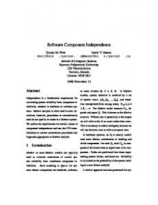
3. Modeling deployment 3.1. The generic model Fig. 1 depicts the four models of the deployment domain. We use: resources, mechanisms, policies and properties. The model of resources contains the entities which are handled during the deployment: the deployed component and the target system. For example, we install the mail server postfix on a computer. The model of mechanisms defines actions having an effect on resources during deployment (install, copy, remove, add, etc). The model of policies contains descriptions of the way in which the mechanism choice is carried out. For instance, a security policy may involve
Figure 2. Deployment meta-model forbidding the installation of programs which decrease the system security level (like ftp). Finally, the model of properties describes the qualities of either resources, mechanisms or policies. They are used to define and parametrize the system goals. The definition of a property exposes the way the system can determine whether an entity has this property. We can specify a property secure which applies to resources using their attribute seclevel. For example seclevel > 4 means that each resource having its attribute seclevel greater than 4 (the valuation scale is a convention and must be commented in the definition of the property) is taken into account. The deployment models are recursive, which means that the handled entities are composed of other entities of the same kind. For example, a resource computer contains the resource software which is composed of the resources component, etc. Thus, each model provides a structured and hierarchical description of an entity. We think that the original aspect of our work is that of the property model. Indeed, generally in tools the properties that are manipulated are fixed and part of the tool’s kernel. Therefore, it is often impossible to use the tool to ensure other (self defined) properties. 3.2. The meta model The corresponding UML meta model is represented in Fig. 2. It represents the concepts introduced above. This diagram is divided into two parts. The first part represents the four deployment models: resources, mechanisms, policies and properties. The second part represents the reasoning part which is presented in [4]. This part is based on a set of deployment rules. A resource: can represent the target system or the deployed entity. • The context description represents all the entities which constitute the resource. It represents an abstraction of the tree structure of the sub-components of the resource. For example, a network consists of several computers each of which has an OS and several applications which are built from components, etc. • The resource dependencies represents the precise definition of the relation between a required and a provided service (either of the same component or of two components). Such a relation is called a dependency. In order to clarify the concept of dependencies, let us examine existing dependencies in the postfix mail server on the GNU/Linux system of Fig. 3. It is composed of four components: Postfix, an SMTP server playing the role of a Mail Transport Agent (MTA), Fetchmail that allows mail to be recovered by an electronic mail transport
Sylpheed
fetchmail FDS ≥ 852
FDS ≤ 1508
¬ poclient ∧ lib
¬ SylpheedDoc ∧ lib Popclient MDA
MUA
spell-Dict
Check
ServeurPop MTA
postfix
procmail
FDS ≥ 1380
fetchmail ∨ MTA MTA
¬ SM ∧ lib
(¬ Smg ∧ lib)
pmail ∨ MUA
MDA
FDS ≤ 248
Amavis
Spam ∧ San
AV
MTA
MDA
MUA
AntiSpam
AV
AntiSpam
Figure 3. The mail server assembly protocol (e.g., Pop) from a distant host (the messages are redirected to the local transport), Procmail, a Mail Deliver Agent (MDA) that manages received e-mails and allows, for example, the filtering of e-mail. Finally, Sylpheed, a mail manager for reading and composing e-mails called a Mail User Agent (MUA). There are three main forms of dependencies: a dependency is either mandatory, optional or negative: – a mandatory dependency (represented by a solid line) is a firm requirement. If it is not fulfilled, installation is not possible. For example, the mail server needs a terminal with a specific CPU or specific libraries, etc. – an optional dependency (represented by a dotted line) specifies that the component may provide optional services. Such services may not be provided (if their requirements are not fulfilled) without preventing the installation. For example, postfix may provide a service for scanning messages against viruses if the service Amavis is available. Otherwise postfix can be installed and provides the MTA service, but the service Anti-Virus AV is not provided. – a negative dependency (expressed by a negation) specifies a conflict forbidding installation. The conflict may concern a service or a component. For example, postfix cannot be installed if another MTA is already installed (such as sendmail). A mechanism: is an action that can be carried out during deployment, having an effect on the target system. It can represent basic actions (for example, to transfer, copy, etc) or more complex actions such as installation, configuration, deinstallation, etc. Mechanisms are chosen using policies. A policy: guides the choice of mechanisms. This choice is based on deployment goals (properties) and deployment conditions. A policy can be basic (for example, to maintain a certain property or a certain value of a system variable) or composite, using other policies, for example, applying better QoS policies only after those relating to resources optimization. Properties are generally used by several policies. Policies are often described using the Event-Condition-Action (ECA) model [7]. In this approach, a policy specifies actions (A) to execute whenever an event (E) occurs and the condition (C) is true. For example, if an alarm ”lack of disk space” occurs on a machine that requires more disk space then the action is to remove obsolete applications. Our approach does not use the ECA
model for describing and modeling deployment, but can be used in implementation. A property: describes the characteristic of resources, mechanisms and policies. The model of properties enables the deployment system to use newly defined properties (we get flexibility) and to enforce the sharing of the same semantics of properties among the entities participating in the deployment. Indeed, using this model, the properties used as goal of the system are not fixed in the system. For example, a machine may have one invariant on its performance and another on its security. A new component enhancing performance but decreasing security would be installed on the first but not on the second. The second interest is that sharing enables the enforcement of a common semantics. For example, an entity that has a property P is sure to share the same meaning of P with all the policies using P. The notion of properties imposes the naming of the properties used but enables the definition, the construction and the reuse of libraries of properties. The deployment rules: check the feasibility of deployment according to the environment requirements (system description) and entity constraints (dependency description). They could also use policies to ensure properties. Once the dependencies are checked by these rules, deployment then becomes possible and actions (mechanisms) are carried out.
4. Deployment architecture The abstract architecture of the deployment is represented in Fig. 4. It is divided into two parts: the real world and the formal world. Our work concentrates on the formal world. In the part of the real world, we have resources (physical context and physical component), mechanisms (deployment engine), policies and properties. To carry out deployment, we need to abstract the real description of each entity: resources (physical context, physical component), mechanisms (deployment engine), policies and properties (left side of Fig. 4). This abstraction results in a formal model to describe all the component dependencies and reasoning engine. Therefore, the physical context and physical component are interpreted respectively in our formal world into a context description and a dependencies (right side of Fig. 4). These descriptions are expressed in a logic language due to its simplicity and expressiveness. The analyzer calculates the relevant context and the most pertinent requirements and information for deployment. Our work focuses on the reasoning engine which takes both the dependency and the context description and checks using deployment rules (installation and desinstallation rules) whether the deployment is possible. For page limitation reason, this part is not presented here, more details are described in [4]. If the dependency descriptions are not resolved then the deployment is not possible. However, if dependencies are resolved, the reasoning engine calculates the deployment effect on the context. Some abstract actions are generated by the reasoning engine and executed in the real world by the deployment engine using the corresponding mechanisms to carry out deployment. These mechanisms represent the different steps in the concrete deployment, e.g. a Makefile of a component may describe its installation process. Policies can also be used to choose the appropriate mechanisms to carry out the deployment. If the deployment is not successful in the real world because of some problems in the physical environment (e.g. a hardware error) then the deployment is stopped and the context is not updated. If no problem occurs during concrete deployment, the physical context is updated, and then the abstract context description is also updated by the reasoning engine. The effect on the physical context should be the same on the abstract description of the context, otherwise we may face inconsistencies. This means that the deployment of a component and more
Real world
Formal world
Resources Physical Context
Context description
Physical Component
Dependencies
Context analyzer
Relevant context
Mechanism
Reasoning engine Deployment engine
Actions
Deployment rules
Policies description
Policies
Policies engine Properties
Key:
Properties description
Abstract data Processing Concret data
Optional flow
Data flow
Figure 4. Architecture deployment precisely here the installation of a component must be coherent with the description used for reasoning. We leave for future work the study of how to maintain the consistency between the real world and the formal word. The formal world aims to guarantee a safe and correct deployment as far as possible before carrying it out in the real world.
5. Conclusion and future work This paper has presented our deployment models and a global view of our architecture of deployment. It aims at providing a fundamental conceptual deployment framework that guarantee the success and safety of installation and deinstallation. A dependency and context descriptions are used by reasoning engine which uses a set of logical rules to check the correct installation and deinstallation. Description and rules are not presented in this paper, they are based on logical formulas and use a dependency graph (see [4]). Checking component installation (resp. deinstallation) is divided into two stages, the stage of checking installability (resp. deinstallation) and installation (resp. deinstallation). Each stage is illustrated and proved in another paper [4]. A prototype of the architecture deployment based on the deployment meta model has been implemented following a component oriented approach. It consists of an architecture of Fractal [5] components and it is being evaluated. We have studied the installation and desinstallation phases and now are working on dynamic updating by studying component substitutability. More work remains to be done to reach our goal of a Safe AUtonomic Network Administration tool. In our current approach, a service is identified by its name. This is clearly very poor and gives the name a central position that it should not have. The identity of a service must be extended to
include interface type and version information. This means a change in a form of subtyping relation to determine dependencies between services. We would like to enable the deployment system to have a parametrized behavior (e.g., personalized deployment which satisfies all the user’s needs or optimized deployment according the platform resources). One solution could be to parametrize the reasoning engine with deployment policies. This extension is related to the introduction of (non-functional) properties in the system. In SAUNA, we mainly consider the security and the performance properties. In the current prototype, a service with two performance levels high and low requires the use of two different names Shigh and Slow (names and value should respect a description consensus (e.g. MIF of DMTF [9])). The problems of this encoding are: (1) How to find all functionally equivalent services? (2) How do we compare Shigh and Svery ? The solution we plan to explore is to extend the services identity to include features, for example, the performance property. A component will declare that it provides a service SP =50 and a component requiring the service S could constrain its performance level SP ≤30 .
References [1] OMG: Deployment and Configuration of Component-based Distributed Applications. Specification version 4, formal/06-04-02, April 2006. [2] A. Hoffmann et al. Specification of the deployment and configuration. Deliverable D2.4, IST COACH Project, July 2003. [3] A. Avizienis, J. Laprie, and B. Randell. Fundamental concepts of dependability. Technical Report N01145, LAASCNRS Toulouse, April 2001. [4] M. Belguidoum and F. Dagnat. Dependency management in software component deployment. In FACS’06International Workshop on Formal Aspects of Component Software, Prague, Czech Republic, September 2006. ENTCS. [5] E. Bruneton., T. Coupaye, and J. Stefani. Fractal Component Model Draft 2.0-2. France Telecom R&D INRIA, Septembre 2003. [6] A. Carzaniga. A characterization of the software deployment process and a survey of related technologies. Technical Report 97-84, Dipartimento di Elettronica e Informazione, Politecnico di Milano, September 1997. [7] N. Damianou, A. Bandara, M. Sloman, and E. Lupu. A survey of policy specification approaches. April 2002. [8] Debian. Debian gnu/linux, 2005. www.debian.org. [9] DMTF. Distributed management task force homepage. www.dmtf.org/home. [10] E. Dolstra, M. de Jonge, and E. Visser. Nix: A safe and policy-free system for software deployment. In Lee Damon, editor, 18th Large Installation System Administration Conference (LISA ’04), pages 79–92, Atlanta, Georgia, USA, November 2004. USENIX. [11] M. Ewing and E. Troan. The rpm packaging system. The first Conference on Freely Redistributable Software, Cambridge, MA, USA, February 1996. [12] R. S. Hall, D. Heimbigner, and A. L. Wolf. A cooperative approach to support software deployment using the software dock. In ICSE ’99: Proceedings of the 21st international conference on Software engineering, pages 174–183, Los Alamitos, CA, USA, 1999. IEEE Computer Society Press. [13] F. Kon. Automatic Configuration of Component-Based Distributed Systems. Phd thesis, Department of Computer Science, University of Illinois at Urbana-Champaign, May 2000. [14] V. Lestideau and N. Belkhatir. Providing highly automated and generic means for software deployment process. In Software Process Technology, 9th International Workshop, EWSPT 2003, Helsinki, Finland, Proceedings, volume 2786 of Lecture Notes in Computer Science, pages 128–142. Springer, 2003. [15] M. Belguidoum. Report on Formalization of dependencies deployment in software component. Technical report, ENST Bretagne, july 2006. [16] A. S. Parrish, B. Dixon, and D. Cordes. A conceptual foundation for component-based software deployment. Journal of Systems and Software, 57(3):193–200, 2001. [17] C. Szyperski. Component Software: Beyond Object-Oriented Programming. Addison-Wesley, 1998.