Supporting Information for:
Removing shadows from consequential LCA through a timedependent modeling approach: policy-making in the road pavement sector Hessam AzariJafaria,b,1, Ammar Yahiab and Ben Amora Interdisciplinary Research Laboratory on Sustainable Engineering and Eco-design (LIRIDE), Department of Civil and Building Engineering, Université de Sherbrooke, Sherbrooke, Quebec J1K 2R1, Canada b NSERC Research Chair on Development and Use of Fluid Concrete with Adapted Rheology, Department of Civil and Building Engineering, Université de Sherbrooke, 2500 Blvd. de l’Université, Sherbrooke, Quebec J1K 2R1, Canada a
Number of pages: 70 Number of figures: 31 Number of tables: 8
1
Contact information:
[email protected] , Tel : +1 819-821-8000 extension: 65504, Fax: +1 819-821-7974
S1
Figure S1. Life cycle system boundary of asphalt and concrete scenarios (PVI stands for pavement-vehicle interaction) ........................................................................................................................................................... 9 Figure S2. Cement production, domestic consumption, and export in Canada (Data collected from Statistics Canada 14, 16 and IBISWorld 15) ............................................................................................................................ 12 Figure S3. Historical and forecasted cost of different fuels ( Biomass 24, Coal 25, 26, Natural gas 27, 28, Waste tire derive fuel 29, and heavy fuel oil 30, 31) for clinker production (Note: the currency is expressed in $ Cdn and are in the base year 2015. Conversion between Canadian and US dollar, where required, has been done at the rate of $1 US = $1.32 Cdn.) The energy content of fuels for clinker production is extracted from different sources 24, 32 and the emissions from fuel combustion are obtained from 33 and 34, respectively. ..................... 15 Figure S4. Historical statistics for steel demand and supply in Canada 42, 43 ...................................................... 19 Figure S5. Annual bitumen production in Quebec 56 and refinery capital replacement rate 55 ......................... 21 Figure S6. The annual price of crude oils normalized for production of 1-liter bitumen from different suppliers of Quebec 59........................................................................................................................................................ 23 Figure S7 Total exchanges in petroleum co-product market due to the short-term change in bitumen demand (LPG= liquefied petroleum gas, HFO= heavy fuel oil, LFO= light fuel oil)........................................................... 26 Figure S8. The annual price of crude oils normalized for production of 1-liter gasoline from different suppliers of Quebec 59........................................................................................................................................................ 27 Figure S9. The annual price of crude oils normalized for production of 1-liter diesel from different suppliers of Quebec 59 ............................................................................................................................................................ 28 Figure S10. Market trend of asphalt manufacturing and possible replacement rate of capital equipment ..... 31 Figure S11. Historical and forecast cost of different fuels for asphalt heating 27, 30, 31, 53 (Note: the currency is expressed in $CDN and are in the base year 2015. Conversion between Canadian and US$, where required, has been done at the rate of $1 US = $1.32 CDN.) ............................................................................................ 32 Figure S12. Estimation of time-dependent IRI for each scenario using Pavement-ME software ...................... 37 Figure S13. The procedure of calculating inventory data for surface roughness-induced fuel consumption ... 37 Figure S14. The procedure for calculating inventory data for flexibility-induced fuel consumption ................ 40 Figure S15. Estimation of time-dependent albedo for each scenario using Pavement-ME software .............. 41 Figure S16. The procedure of calculating inventory data for RF effect and linking to CO2 balance .................. 42 Figure S17. Schematic view of time-dependent instantaneous radiative forcing of a unit mass pulse emission at time zero for carbon dioxide and radiative forcing induced by albedo change ............................................ 43 Figure S18. The procedure of calculating the change in electricity demand due to the UHI effect .................. 45 Figure S19. Analysis results of electricity consumption as a function of hourly temperature for winter a) and summer b) .......................................................................................................................................................... 48 Figure S20. The procedure of calculating inventory data for carbonation effect and linking to CO2 balance... 49 Figure S21. The procedure of calculating inventory data for lighting electricity and linking to affected technologies ....................................................................................................................................................... 51 Figure S 22. Time-dependent contribution results of climate change category ................................................ 56 Figure S 23. Time-dependent contribution results of human health category.................................................. 57 Figure S 24. Time-dependent contribution and base-case results of ecosystem quality category ................... 58 Figure S 25. Time-dependent contribution and base-case results of resource category .................................. 59 Figure S26. Total contribution of life cycle phases in consequences of shifting from BAU to ALT scenario (CC=Climate change; HH= Human health; EQ= Ecosystem quality; R= Resource) ............................................. 60 Figure S27. Time-dependent cumulative emissions and contribution of four major greenhouse gases to climate change results........................................................................................................................................ 61 S2
Figure S28. The contribution of life-cycle components to the variance of each damage category................... 62 Figure S29. Comparison of static and dynamic inventory results (Static characterization factors were used for all the scenarios. Normalized results more than 100% show an overestimation in the environmental credits given to the substitution of BAU with ALT and vice versa. In static affected technology scenario, we considered similar modeling framework to dynamic except that we only linked the demand to long-term affected technologies. In static use phase modeling and static affected technology, in addition to isolating the affected supplier to long-term technology, we computed the use phase modeling by static inputs. List of input parameters is available in Spreadsheet SI, Table S1). .............................................................................. 63 Figure S30. Sensitivity analysis of the dynamic vs static inventory and short-term period of 5 and 10 years . 64 Figure S31. Sensitivity analysis of the increasing and decreasing the intervals of repair schedules for two years ................................................................................................................................................................... 64
Tables Table S1. Repair schedule of ALT and BAU pavement scenarios ......................................................................... 7 Table S2. The procedure for identifying the determining product in petroleum production (WTI crude oil)... 25 Table S3. Induced production of the demanded co-product (highlighted in yellow) and by-products from crude oil refinery of WTI per Liter demand........................................................................................................ 25 Table S4. The procedure for identifying the determining product in petroleum production (WCS crude oil).. 29 Table S5. Induced production of the demanded co-product (highlighted in yellow) and by-products from crude oil refinery of WCS per Liter demand....................................................................................................... 29 Table S6.Summary of affected technologies in different time horizons (WCS = West Canadian Select, WTI = Western Texas Intermediate)............................................................................................................................. 33 Table S7. The proposed value of concrete carbonation rate (𝑚𝑚𝑚𝑚/𝑦𝑦𝑦𝑦𝑦𝑦𝑦𝑦) 98..................................................... 50 Table S8. Overview of pavement class descriptions and illumination demands Class ...................................... 52
S3
Modeling details Life cycle assessment (LCA), as a tool, helps decision-makers quantify, analyze, and compare environmental impacts of different types of product or service from material extraction (cradle) to their end of life (grave) phase. The LCA procedure starts from drawing a schematic view of life cycle phases of the production system from cradle to grave (i.e. the goal and scope definition step). Then, the quantification of the environmental inputs and outputs associated with each life cycle stage is conducted (Life cycle inventory step). After that, the quantified elements will be aggregated and classified to a lower number of categories to facilitate the decision-making process (Life cycle impact assessment step). Then, the evaluation of findings in relation to the defined goal and scope is performed in the last step (Life cycle interpretation).
1. Goal and Scope and functional unit definition The purpose of this study is to evaluate the environmental impacts of increasing the use of concrete pavement as an alternative (ALT), a concrete pavement, instead of the business-as-usual (BAU) case, herein asphalt pavement. For this purpose, this research is intended to support a decision where the product (concrete pavement) is evaluated as an alternative for the construction of new pavements in Quebec. The obtained results can provide decision support in situations where governments consider to increase the application of concrete in new road construction projects. It is worthy to mention that this study only includes “small changes” for different resources used in the life cycle of pavement. Indeed, changes in the demand of intermediate flows will not alter the overall trend in the market. The functional unit of this study is “providing traffic service over the whole length of two lanes road in Quebec urban area with 20,000 AADT, including 5% truck, for a 50-year lifespan”. This functional unit comprises 287.2 km of Quebec roads according to the MTQ statistics. All these road surfaces within this functional class are currently covered by asphalt (BAU scenario) and the reconstruction of S4
all the road length is assumed to occur during one year in different regions of the province of Quebec. The consequences of the changes in construction material demands for this decision are assumed linearly. For example, a rough estimation for this FU size reflects 174,000 t of increase in cement demand while the production capacity of Quebec is in the order of 10 Mt. Therefore, the demand change for cement cannot affect the overall market situation, and therefore could not bring into play new markets or new products and technologies. The baseline year of this case study is considered as 2018, when the construction of the pavements is initiated.
2. Life cycle stages and time horizons All the life cycle stages of pavement are characterized by different types of construction materials, such as cement (binder material for rigid pavement), aggregates, steel, bituminous materials (binder material for flexible pavement), and water. The thickness of pavement layers in cold regions, such as the pavements in Quebec, are significantly larger than those in mild weather regions to satisfy freezing depth and traffic service. Consequently, a considerable volume of the materials must be transported from raw materials manufacturers to plant or to the construction site. Due to the large volume of the required materials, it is important to limit the transportation distance, hence reduce the construction cost and environmental impact. In fact, the market for products with a low value to weight ratio tends to be local 1. The steel manufacturing can be considered as an exception, which has a global market size since a major part of steel, utilized in Canada, is imported from the U.S. and China 2. The systems are modeled from cradle to grave in this study. The pavement product system includes five different stages, including materials production, pavement construction, pavement use, maintenance and repair, and end-of-life. The BAU lifespan of 49 years is considered, assuming a certain number of resurfacing
S5
to maintain the serviceability. Similarly, the ALT pavement lifespan is 49 years, but a layer of bituminous asphalt will be used to resurface the concrete pavement after 38 years of age. A. Materials production: This stage includes the production processes of the materials used for the construction of pavement layers, from raw materials extraction to their transformation into the final product. According to Weidema, individual demands of different sectors of consumers may imply that capacity adjustments should be seen as a continuous process, and therefore these demands affect the current and expected trends in the market volume 3. However, in the case of pavement materials for new construction and for the functional unit used in this study, short-term changes in demand for the materials are not continuous. In fact, there is no regulated shape of consumption for the selected pavement alternative with the specified traffic level. As a result, there is no implication of continuous demand for the required investments. Indeed, in the case of pavement construction, market situation of the materials has little influence on capacity adjustments considering significant production capacity and long life cycle of the infrastructures for the materials production 4. For example, for the new construction of pavements, the change in material’s demand may not require a new capacity installation. It should be noted that long-term affected suppliers can provide parts of construction materials implemented for repair stage since the government may possibly predict the required repair materials that are procured in the next 5-10 years. B. Pavement construction: All the execution phases of surfaces and the sub-layers construction, including equipment fuel, consumption and their resulting emissions to the environment are considered and analyzed at this stage. C. Maintenance and repair (M&R): These tasks are essential for recovering functionality of the pavements over their lifespan period. The repair schedule of the pavements is necessary to restore the value of the pavement, including surface roughness and albedo in the use stage. The equipment required S6
in this stage are considered as long-term substitutions since the repair activities begin only 15 years of the service. Therefore, adequate anticipation for the capacity increase will be considered to supply this demand. Details of tasks and their corresponding quantity are shown in Table S1. The lifespan of the pavements is considered to vary as a consequence of different external criteria, such as premature failure in materials (e.g., low quality of placing pavement layers during construction and maintenance can result in a premature deterioration during warm or cold seasons5). This variation comes with a repair schedule to maintain the serviceability of the structure.
Table S1. Repair schedule of ALT and BAU pavement scenarios Concrete pavement Process (year of occurrence,
Asphalt pavement Process (year of occurrence, shorter repair
sensitivity analysis shorter interval, sensitivity
interval, longer repair interval)
analysis longer interval) Pavement construction (0)
Pavement construction (0)
25% of joint restoration (10, 8, 12)
Removing a 40-mm layer, leveling, and resurfacing (15, 13, 17)
Restoration of all joints and 25% grinding (20, 16, 24)
Removing a 50-mm layer, leveling, and resurfacing (28, 24, 32)
100% grinding of the surface layer (30, 24, 36)
Removing a 50-mm layer, leveling, and resurfacing (40, 32, 45)
Asphalt resurfacing (a 50-mm layer) (40, 32, 48)
Removing a 50-mm layer, leveling, and resurfacing (-, 42, -)
Asphalt resurfacing (a 50-mm layer) (-, 40, -)
-
D. Use stage: This stage includes emissions that are related to the use of pavement during its service life. Extra car fuel consumption induced by surface roughness and structural rigidity of pavements, albedo effect of pavement as a result of radiative forcing intensification and urban heat island effect, S7
and lighting energy for road illumination are included in this stage. In addition, in ALT scenario, concrete carbonation was considered. To assign the appropriate time horizon for the stage, the following consideration was consistently applied to the model: Unlike the materials production stage, the accumulated demand of fuels and electricity result in an installation (when there is an increase in demand) or phasing out (when there is a reduction in the demand), which are the basis for decisions on capital investment 3. Indeed, due to the long-lifetime (after 5 or 10 years of service), there is a potential for installing new supplying capacity because of the accumulated change in demand. Therefore, this part of demand changes in the use stage over time is supplied by a new installed capacity (i.e. the long-term affected technology). Nevertheless, the supply and the demand during the short-term period (e.g. the first 5 or 10 years of service life) are covered by the existing capacity. E. End-of-life: This stage refers to materials recycling and landfilling. The main processes in this stage are demolition and transportation of waste, equipment fuels consumption and emissions, as well as waste landfilling. A proportion of demolished materials is recyclable, which influences the market for virgin construction materials with the same function. It can be well anticipated that the pavement materials can be recycled at the end-of-life in advance. Therefore, this substitution involves only longterm effects, i.e. effects from installation and production of newly installed capacity. Hence, the recycled materials recovered in this stage are replaced by the materials produced through the long-term affected supplier (50 years after the construction stage).
S8
Concrete
Steel rebar production
Binder production Aggregates preparation Base and Subbase preparation Salt production
Asphalt
Binder production Aggregates preparation Base and Subbase preparation Salt production
Production Mastic asphalt production
Asphalt production Concrete production
Asphalt production
Asphalt emulsion production
Pavement construction
Energy
Materials production Preparation
Maintenance and repair
Use
End of life Landfilling
Scraping and joint repair
Joint and dowel rebar installation
Milling, paving and rolling
Sub-base, base, and surface compaction and rolling
Concrete Use (albedo, PVI, carbonation, lighting)
Recycling
Salt placing
Milling, paving and rolling
Sub-base, base, tack coat, and surface compaction and rolling
Salt placing
Landfilling Asphalt Pavement Use (albedo, PVI, lighting)
Recycling
Emissions
Illustrate transport (beyond sequence) Illustrate only the sequence
Figure S1. Life cycle system boundary of asphalt and concrete scenarios (PVI stands for pavement-vehicle interaction)
3. Procedure for identifying short-term and long-term affected technologies Once a technology is installed, further changes in short-term demand will still affect the older technology, because this latter is often the costliest to run. It is important to understand that even though the short-term fluctuation will constantly affect the older technology in the short-term, it is the accumulated changes in the short-term demands that make up the long-term changes, which eventually lead to the installation of the new capacity. The long-term effect of the demand is, therefore, the additional exchanges from the newly installed technology. Various researchers explained the fundamental of consequential modeling. According to Weidema 6, it is the change in demand for the studied product that is modeled in the consequential framework. A cause and effect relationship between the change in demand and the related changes in supply is
S9
generally investigated. In fact, the studied product is considered to be produced by an additional capacity in the case of an increasing trend in the market. This additional production capacity must come from unconstrained suppliers. Allocation problems are always dealt with using system expansion 7, which is also a priority in allocation approach of ISO 14044 8. The procedure for identifying the affected technology is performed through the step-wise procedure proposed by Weidema et al. 9. In the first step, this procedure considers the time horizon of the consequences in which the changes in demand and corresponding supply happen (short and long-term). Then, the markets affected by the changes are identified. The second step consists of identifying the markets trend and the products constraints. In the last step, the most sensitive process to change the demand is determined and applied to the model as the affected technology. In the case of an increasing or steady market, the affected technology is the unconstrained one with the lowest long-term production cost. On the other hand, the highest short-term cost technology is the affected one when the market trend is rapidly decreasing (decreasing at a higher rate than the capital replacement rate) 7. An important aspect of the end of life stage is the modeling of avoided environmental burdens from recovered and re-used waste. There are certain exceptions of stable and mature market for recycled products, such as pozzolanic materials for concrete production. For example, the markets for pozzolanic materials are mature, i.e. nearly 30-50% of the pozzolanic materials obtained from byproducts at present globally is already in use 10. Nevertheless, these materials belong to a constrained resource and therefore cannot be the affected suppliers to a demand-driven market that has other unconstrained suppliers 7. Recycled materials with high demands belong to mature markets (i.e. where supply matches demand) in which all the recycled material is already consumed or to be consumed in short-term. Therefore, the increase in demand for recycled materials cannot be fulfilled considering such a physical constraint 3. S10
Affected technology in foreground system a) Concrete manufacturing
The statistical data is obtained from various sources, such as Statistics Canada and IBISWorld
11, 12
.
Concrete ready-mixed industry in Canada involves a steady growth of 2.5% in recent five years according to IBISWorld report 11. This growth is predicted to continue at the rate of 1.6% in the next five years benefitting from improved facilities and construction of transport infrastructure. The technology of concrete production in Quebec focuses on wet mix type plants, where water is mixed with cementitious materials and aggregates in the plant rather than introducing water to the dry materials in the truck mixer. Since more than 75% of the concrete production cost comes from materials procurement 12, less attention is paid to the technological development and optimization of the cost in ready-mix plants 13. Hence, the distance from the plant to the construction site may be the key factor in the price adjustment of the manufactured concrete. We considered the nearest plant to the construction site as the long-term affected technology accordingly. For the short-term effect of a change in ready mixed concrete production, the ready-mix plant with farthest transportation distance to the understudied urban area is selected as the supplier with the highest short-term cost. b) Cement manufacturing
In 2009, Canadian cement manufacturers exported more than 3.4 Mt of cement and clinker to the U.S., which is approximately one-third of Canadian production
14
. During 2010, cement manufacturers
produced over 12.4 Mt of cement. Canada exports more than 30% of its total cement production, mainly to the U.S. The major Canadian cement import comes from Asia for Western Canada (around 20% of the whole consumption), and the central parts, such as Manitoba, are partially fed by suppliers from Montana. However, this practice does not affect the cement market in Quebec 15. As can be observed in Figure S2, since the post-financial crisis era, cement production and consumption have been
S11
dramatically raised. The consumption data consistently omits cement manufactured or imported by the nonparticipating sellers in the survey by Statistics Canada. The exact value of the omitted amount is not specified, but it may include up to 12% of domestic consumption in Quebec and up to 3% of total consumption in Canada 14.
Cement mass (Million tonne)
14
y = 0.0732x - 135.38
12 10 8 y = 0.1276x - 247.84
6 4
y = 0.0678x - 133.18
2 0 2009
2010
2011
Production
2012
2013
2014
Domestic consumption
2015
2016
2017
Export
Figure S2. Cement production, domestic consumption, and export in Canada (Data collected from Statistics Canada 14, 16 and IBISWorld 15)
The current production capacity of cement plants in Quebec is 3.9 Mt per year and only 1.9 Mt of the produced cement is consumed in Quebec
14, 16
. Considering the average percentage of export to the
U.S. from Canada (29.7% of the total production according to Figure S2), around 70.3% of the current production capacity is consumed locally. Considering the effects of a marginal increase in cement production, the short-term scenario focuses on one of the existing cement manufacturers, while in the long-term scenario, the new supplier will probably be installed in later years, which will be the affected one. Current cement manufacturers in Quebec are supplying the demand for different technologies S12
(Lafarge, CRH, Ciment Quebec, or Colacem plants). For the short-term affected technology, the oldest technology (dry kiln) operating in Quebec 17 with the longest transport distance is selected, because it is the costliest system to run. It should be noted that the cap-and-trade system regulated in 2013 forced various industrial sectors that are intensively emitting greenhouse gases (GHGs) to upgrade to less emitting facilities 18. Otherwise, they are mandated to purchase credits to make up for more GHGs than the 25,000 t 19. These regulations can increase the price of the cement produced by older technologies, such as dry kiln process since their fuel combustion for cement production emits a significant volume of GHGs (0.39 t/t clinker for steam coal) 4. An increase (from $16.4 to $18.08 per tonne of CO2eq in 2020) in a carbon tax of Quebec will be the evidence of an increase in cement production cost with older technologies that emit a higher quantity of GHGs rather than the recent ones with preheater and precalciner. As a result, it would be a political constraint on the suppliers with the older technologies in the long-term frame. It cannot be feasible to predict construction of a new cement plant in a region unless the investments and the plan have been drawn for a long time, because the plant construction cost has a long payback period. However, a new supplier (e.g. new cement plant) is likely to be available to cover the additional demand of the region. In Quebec, it is announced from the early 2000s than the next cement plant that is going to supply the demand is McInnis aiming to produce 2.2 Mt per year. The new plant is claimed to consume 3,100 MJ/t of clinker and overall consumption will be less than 90 kWh/t of cement produced. The used technology will reduce the energy for clinker production by up to 29% compared to the dry kiln 4. c) Fuel for clinker production
The fuel for clinker production includes coal, natural gas, oil (e.g. residual/heavy fuel oil), and alternative sources, such as waste tires and biomass 17. With respect to identifying the affected fuel, primary data sources are used to determine the production cost. There are different grades of coal as S13
fuels, which are distinguished by their carbon content. The higher carbon content corresponds to the higher quality of the fuel. In the cement industry, steam coal is mainly used to cover the heat combustion for calcination. Expansion of natural gas in the cement industry, which induces a slowing export intensely, is decreasing by 15% 20. There is not any coal mine in Quebec and only 1% of the total energy consumed in industrial section (equivalent to 23 PJ) comes from coal, which is supplied by Central Appalachian mines, such as those in New York and Pennsylvania in the U.S. The marginal price of the coal is determined by the aggregation of coal production and the transportation to Quebec. The coal cost is one of the most competitive ones according to Figure S3. The use of heavy fuel oils is substantially decreasing due to the recent banning policy of Quebec government on the fuel with high sulfur content
21
. Natural gas, tire-derived fuels (TDFs), and biomass are increasingly used in this
industrial sector. Since 1993, Quebec government has implemented several programs to stimulate the recovery, recycling, and recovery of used tires in Quebec
22
. For the short-term supplier, the natural
gas as the affected supplier by the change in clinker fuel demand is considered owing to the highest short-term cost. The plant corresponding to the long-term affected supply of cement signed a cooperative agreement of using forest biomass as an auxiliary fuel, which is the first alternative for the cement plant and constitutes a fuel source in abundant supply in the region. The source of biomass is located in St-Elzéar with a distance of 100 km to the plant. The produced biomass is the residue of wood processing (bark, sawdust and shavings, trim ends, edgings, etc.) or slash (branches, needles, leaves, etc.). The mass quantity of biomass produced in this area is constrained by the volume of determining co-product (i.e. timber) since it contributes little to the total revenues of the corresponding unit process (e.g. sawmill). However, in Quebec, there are political targets for 2030 and beyond in place to increase the proportion of biomass, which will contribute to developing a market for biomass
S14
in long-term 23. Therefore, the biomass is considered as the unconstrained product for the calcination process in long-term. 16.00 14.00 12.00
$/GJ
10.00 8.00 6.00 4.00 2.00 0.00 1990
1995
2000
2005
2010
2015
2020
2025
2030
2035
Year Appalachian steam coal
Heavy fuel oil
Natural Gas
Waste tire derived fuel
Biomass
Figure S3. Historical and forecasted cost of different fuels ( Biomass 24, Coal 25, 26, Natural gas 27, 28, Waste tire derive fuel 29, and heavy fuel oil 30, 31) for clinker production (Note: the currency is expressed in $ Cdn and are in the base year 2015. Conversion between Canadian and US dollar, where required, has been done at the rate of $1 US = $1.32 Cdn.) The energy content of fuels for clinker production is extracted from different sources 24, 32 and the emissions from fuel combustion are obtained from 33 and 34, respectively.
d) Aggregates manufacturing
Although aggregates (sand and coarse aggregate) are costless solid materials of the mixtures (approximately $20/t aggregate versus $140/t cement), a significant volume of sand and gravel is required to manufacture the concrete and asphalt mixtures. Hence, due to this low price to mass ratio, the aggregate’s market, similar to the ready-mixed industry, is highly dependent on the local suppliers. For nearly 15 years, the sand and gravel industry is quite stable in Quebec and about 300 manufacturers, spread over the province, are producing an average of 30 Mt aggregates per year35. The major application of sand and gravel in Quebec (55%) is in the road construction and maintenance 35. There
S15
are more than 300 aggregate mines in Quebec and various infrastructure projects supply their demand majorly from the nearest mine to minimize the final cost of the aggregates. Another parameter, which influences the price and the application of the aggregates, is their surface texture. Particularly, in concrete mixtures, the shape of sand particles plays an important role in the cement content of concrete to satisfy workability and targeted hardened properties. Generally, natural sands are being used in conventional and high-performance concrete mixtures, since a lower volume of the binder is required to achieve the desired workability and mechanical properties of the mixture compared to the use of crushed sands. As a result of using crushed sand instead of natural sand, water demand will increase by 6 to 9 kg/m3 and the sand content by 2 to 3% in the mixtures 36. As a consequence of the increase in water content and considering a constant water-to-cement ratio, the relative increase in cement content is required. The short-term supplier of the sands in concrete is the crushed sand since it is the less preferred (less competitive) and unconstrained in the sand market. On the other hand, natural resources are already fully utilized. On the one hand, the natural sand production is limited to the areas near rivers. The increasing difficulty in extraction has a negative effect at the bottom line for mines. On the other hand, asphalt producers prefer asphalt mixture made with crushed aggregates since the crushed sand is cheaper (due to its abundance and simple manufacturing process) and the infrastructure for its production can be installed in almost every projects site with an appropriate area, i.e., a place relatively far from urban neighborhood and with access to water source. Although generally abundant, high-quality sand and gravel mines are not plentiful in most parts of southern Quebec. A limited and non-renewable resource whose exploitation is often reduced to restricted areas may not be simply quarried and produced in that region. For example, Montreal manufacturers, representing almost half the population of Quebec, consumes half of the aggregates S16
production of the province, while its resources in the sand and gravel are limited. Depleting natural sand and strict environmental regulations on mining (as two constraints for natural sand manufacturing) gradually shifts the attention towards an alternative for fine aggregates. Crushed sand will be available to produce a concrete mixture and therefore is the long-term affected technology. Considering the use of crushed sand in the mixture, an increase in the concrete matrix phase (sand content by 2.5% and water and cement content by 7.5 kg/m3) and, consequently, reduction in gravel content is applied to the mixture. e) Water supply
Similar to other concrete ingredients, water consumption is growing in Quebec. Supplying qualified water for concrete production in Quebec is not a big deal since this area has fresh water and the water is plentiful. Most of the batching plants supply their own water demands by means of different wells dug in the batching plant site. It is also conventional to use the water that has been already used for washing aggregates and truck mixers in a concrete plant. The used water is a by-product of the aggregate and mixers washing and its content is dependent on the determining co-products (washed aggregates and cleaned mixers). Therefore, the recycled water cannot supply the increase in water demand. Short-term and long-term affected technology for water supply is the only remained supplier, which is well water in batching plant. f)
Chemical admixtures
The role of chemical admixtures in concrete production is inevitable in this century to improve the properties and durability of concrete. Besides, different chemical admixtures are part of the conventional ingredients of the structural concrete mixtures produced in Canada. However, no historical data is available for supply and demand of these admixtures in Canada. In addition, the market trend is concrete manufacturing is moderately increasing (2.5% growth). As a result, it is S17
expected that the chemical admixtures market poses an increasing demand similar to the U.S. and other parts of the world
37, 38
. The application of these admixtures (e.g. superplasticizers, air entraining
agents, etc.) aims to modify and improving properties of concrete. The short-term effect of an increase in demand of superplasticizer is on the oldest technology of superplasticizer, namely lignosulfonatebased admixtures, which is required in greater quantity due to the lower efficiency compared to other admixtures. The average dosage used in the concrete mixture is assumed 1.5%, by mass of binder. The most preferred technique is the lately developed Polycarboxylate based superplasticizer, which performs better in the improvement of fresh and hardened properties of concrete. Its typical content in a concrete mixture varies 0.5% - 1.0%, by mass of cementitious materials, for conventional concrete. The inventory for the chemical admixtures was obtained from the UK chemical admixture association 38
. g) Steel rebar manufacturing
The reinforcing rebar supply chain can be divided into two markets, crude steel and rebars manufacturing. An increasing trend in reinforcing rebars production and consumption are observed in recent five years (1.7%). This increase is expected to continue in the future 39. In Fact, the future of the rebars highly depends upon the construction industry, since this sector consumes almost the whole production outcomes. There will be a significant increase in non-residential construction, from 2014 2024, more than 47,000 projects are aimed to build in the form of different infrastructures, such as bridges, subways, and rails 40. In addition, in 2016, the federal government announced an increase in spending on infrastructure projects over the next five years; an estimated $60 billion of new investment over the next 10 years, including an additional $10 billion over the next two years. Generally, two main steel manufacturing technologies have been supplying the demand in the world, namely the electric arc furnace (EAF) and blast oxygen furnace (BOF). The EAF consumes most of S18
the scrap steel in the market. Steel scrap is a fully utilized by-product and is not the determining coproducts in its production process. Therefore, production of steel by this technology cannot affect the output from plants that use scrap steel and therefore, is technologically constrained 41.
20000
Crude steel mass (metric tonne)
18000
Slope = 1.6%
16000 14000
Slope = -1.2%
12000 10000 8000 6000
Slope = 12.6%
4000 2000 0 2010
2011
Total crude steel production
2012
2013
2014
Apparent steel use (equivalent to crude steel)
2015 Steel import
Figure S4. Historical statistics for steel demand and supply in Canada 42, 43
So far, the largest geological source of iron in Canada is the Labrador Trough in the adjacent of Labrador province and Northern Quebec. These mines account for virtually all the iron ore mine in Canada. According to Figure S4, although the steel demand is increasing, the local production has been decreased since 2010 and the government is forced to import the remainder. Protectionist legislation and the dramatic increase in foreign imports resulted in a significant drop in exports (-6.1%), while imports recorded an unprecedented growth of 16.4% in 2014-2015
S19
44, 45
. The rebars produced with
BOF technology that are imported from Germany has the highest short-term cost between the existing suppliers 46 and, therefore, is considered as the short-term affected supplier. The import price of rebars in some cases (particularly from China) is lower than other suppliers, even from that of produced in Canada 47. However, the Canadian International Trade Tribunal’s new policies on anti-dumping and subsidizing will act as a political constraint on further imports to improve the local market 48. The long-term affected supplier of rebars is, therefore, the nearest local supplier inside Canada with the emerged technology. In the prospective scenario, according to Weidema
41
and
Morfeldt et al. 49, the affected technology can be changed in time. The affected technology later than 2040 is expected to be “blast furnace with carbon capture and storage and top gas recycling” since it is the newest technology supplier that is going to be developed in future to cover the demand in the corresponding years. Since the inventory list for this technology is not available in the ecoinvent datasets, the all the environmental and economic flows for this process are obtained from IPPC report 50
. h) De-icing salt manufacturing
De-icing salt is one of the commodities that is available with different chemical bases. The policy of local transportation government is on the optimum use of de-icing salts and, therefore, no policy constraint is included in the salt type
51
. Abundant mass of sodium chloride salt in Quebec can
guarantee long-term supply of roads de-icing. The affected technology would be the most preferred technology since the trend of salt manufacturing has been almost steady since 2010
52
. The highest
short-term price between the alternatives of de-icing salt is calcium chloride, which is able to de-ice the road surface at the same efficiency level of sodium chloride. The lowest price belongs to sodium chloride and the affected supplier would be the mine with the shortest distance of transportation.
S20
i)
Bitumen
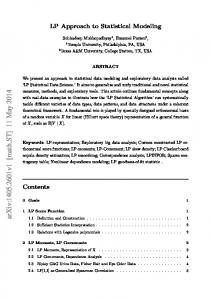
Bitumen, gasoline, and diesel are of the co-products of crude oil refining. Same as other multifunctional processes, determining co-product(s) should be identified to assign the environmental impacts of the process. The determining co-product(s) are product(s) of a multifunctional process that a change in their demand will affect the production volume of the process. Since the road network in Quebec is already developed and no further significant capacity expansion is expected, demand for bitumen will only come from roads repair and maintenance as well as the road reconstruction. As can be observed in Figure S5, the demand for this product is slightly decreasing and the same decrease trend is forecasted until 2021 53. To identify the most likely supplier that is affected by bitumen demand, the speed of the replacement rate for production equipment is considered. Steeper slope of the capital replacement than the overall market trend leads to selecting the most competitive supplier in the market for the long-term affected supplier
54
. In general, the replacement rate for
equipment is determined by the inverse estimated lifetime of the equipment. For the refinery, it is reported that the capital equipment lifetime is approximately 20 years 55. 1000
Production (megalitres)
900
Slope = - 1.1%
800 700 600 500
Slope = -5.1%
400 300 200 100 0 2004
2005
2006
2007
2008
2009
Linear (Bitumen manufacturing in Quebec)
2010
2011
2012
2013
2014
2015
Linear (Capital replacement rate)
Figure S5. Annual bitumen production in Quebec 56 and refinery capital replacement rate 55 S21
Different factors, such as supply (affected by current condition and future expectation of capacity, geopolitics, weather, etc.), demand (affected by current condition and future expectation of economic and population growth, personal and industrial transport, etc.), physical balancing, and market behavior (options, swaps, spreads, and futures of energy price) influence the formation of crude oil prices. Supply contracts of oils are short-term, and sources can be changed very quickly if crude oil producers offer better prices
57
. Crude oil is totally imported to Quebec and the supplier countries varied
significantly per year [24]. The import data and corresponding price of imported crude oil are not available and, therefore, the crude oil market is simplified by classifying the suppliers to the following three categories. Current suppliers of crude oil in Quebec are divided into the U.S. (WTI), Western Canada (WCS), and the organization of the petroleum exporting countries (OPEC). The low-sulfur type of crude oil is considered for the OPEC crude oil imported to Quebec (which comes from Algeria, Nigeria, etc.)
58
. The U.S. has been greatly increasing their market share, because of lower prices
offered by the American and Canadian producers, notably for the crude oil imported by train and ship from North Dakota and Texas, respectively. The bitumen production price is adjusted based on the price of the crude oil assuming a similar cost of the refinery for the different alternative suppliers. The WCS oil will naturally receive a lower price in the marketplace due to less valuable refinery products but more residual materials such as bitumen. Therefore, according to Figure S6, the WCS oil, which yields almost 29% of bitumen per barrel of crude oil, has the lowest price in the market compared to the other suppliers. For the short-term affected technology of bitumen, the U.S. crude oil imported by train was taken into account. For the long-term effect of the change in bitumen demand, we assume that the oil production in WCS is the affected supplier (see Figure S6).
S22
18 16
$/L Bitumen
14 12 10 8 6 4 2 0 2009
2010
2011
Bitumen_WTI
2012
2013
Bitumen_WCS
2014
2015
2016
2017
Bitumen_OPEC
Figure S6. The annual price of crude oils normalized for production of 1-liter bitumen from different suppliers of Quebec 59
Since bitumen is a co-product of petroleum production, the procedure of identifying the determining product is necessary to assess the consequences of demand changes of the multifunctional process. This procedure is extensively described in Schmidt and Weidema
60
, and Weidema 9. The crude oil
refinery is assumed as a joint process (i.e. the output of the co-products cannot be varied independently) and a demand change for one of the co-products might induce an increase in the production volume of the process. The outputs of WCS oil are significantly different from those in WTI and OPEC oils since the latter sources yield fewer residues and larger volume of lighter co-products. The petroleum coproducts do not have any alternative way of production although some flexibility exists, notably in the bitumen market (e.g. bioasphalt as a long-term substitution of bitumen). Therefore, a change in the production volume in short-term can influence the output, pricing and consequent consumption of all the other refinery co-products. According to Weidema 3, joint products that do not have any alternative production routes have the same normalized market trend, since only then the market will be cleared. In this situation, a change in demand for one of the co-products will influence the production volume S23
of the crude oil in proportion to its share in the gross margin of the refinery process (similar to economic allocation in attributional LCA). The overview of the co-products and their contribution to revenue, induced production, and consumption as well as the net changes in consumption, which are induced by demanding each by-product, are presented in Table S2 and S3 (WTI oil). The prices of petroleum coproducts were obtained from 61, 62, 30, 63 and 64. The procedure of finding the determining products in a joint production system that have more than one product without alternative production routes are explicitly described in 65. It should be noted that the changes in the demand of the other co-products may affect their consumption and disposal phases. Therefore, in case of no alternative route of production for the co-products (Table S3), a demand change for 1-liter bitumen from the short-term supplier induces a 0.73-liter crude oil refinery (of which 0.03 liter bitumen, see Figure S7) and the rest of the demand, i.e. 0.97-liter bitumen, shall be supplied from the reduction in consumption of bitumen by the marginal consumers. As a simplification, in this study, it is assumed that the 0.97-liter bitumen is supplied by the un-demanded production induced by other co-products such as diesel and gasoline (See section j. Diesel and gasoline).
S24
Table S2. The procedure for identifying the determining product in petroleum production (WTI crude oil) Product
Average Output from a Barrel of Oil 66, 67
Price
Revenue
$/Liter
$/Liter crude oil
%
Bitumen
4%
0.64
2.6
3%
Diesel
27%
0.89
24.9
28%
Gasoline
43%
1.08
50.8
58%
Heavy fuel oil
5%
0.45
2.3
3%
Light fuel oil
3%
0.58
1.7
2%
Liquefied petroleum gas
2%
0.46
0.9
1%
Jet fuel
6%
0.81
4.9
6%
Rest (Relatively small quantities)
6%
-
0.0
0%
Total
-
-
88.0
100%
Table S3. Induced production of the demanded co-product (highlighted in yellow) and by-products from crude oil refinery of WTI per Liter demand Induced
production
when
Bitumen
Diesel
Gasoline
Heavy fuel oil
Light fuel oil
LPG
Jet Fuel
Bitumen
0.03
0.04
0.05
0.02
0.03
0.02
0.04
Diesel
0.20
0.28
0.34
0.14
0.18
0.15
0.26
Gasoline
0.34
0.48
0.58
0.24
0.31
0.25
0.43
Heavy fuel oil
0.04
0.05
0.06
0.03
0.03
0.03
0.05
Light fuel oil
0.02
0.03
0.04
0.02
0.02
0.02
0.03
Liquified petroleum gas (LPG)
0.01
0.02
0.02
0.01
0.01
0.01
0.02
Jet fuel
0.04
0.06
0.07
0.03
0.04
0.03
0.06
Rest
0.04
0.05
0.06
0.03
0.03
0.03
0.05
Induced determining products
0.73
1.01
1.23
0.51
0.66
0.52
0.92
Total induced production
0.73
1.01
1.23
0.51
0.66
0.52
0.92
demanding 1 Liter by-product
S25
Induced consumption of petroleum by-products 0.34 lit
Gasoline Diesel
0.20 lit
0.04 lit
HFO LPG LFO
0.01 lit
0.03 lit
Market for bitumen from WTI supplier
0.02 lit
Rest of residues Jet Fuel
Petroleum refinery coproducts
1 lit 0.04 lit
0.04 lit
Consumption reduction of bitumen
0.97 lit
Figure S7 Total exchanges in petroleum co-product market due to the short-term change in bitumen demand (LPG= liquefied petroleum gas, HFO= heavy fuel oil, LFO= light fuel oil)
We assumed that the most likely compensating bituminous material as bio-asphalt since this is identified as one of the rare products that are able to exert the same properties of petroleum bitumen. The availability of abundant forest wood in Quebec makes the development of bio-asphalt very facilitating to change the asphalt-paving industry in the coming years dramatically. In the long-term scenario, we consider the innovative technology of bio-asphalt as an alternative route for supplying the bitumen demand in the market. Therefore, in the first stage, it should be identified if the bitumen is the determining co-product. Since it is assumed that other co-products rather than bitumen have no alternative route of production, the change in the demand of bitumen will not affect the capacity of S26
crude oil refinery production. Instead, the bitumen alternative route, i.e., the bio-asphalt, supplies the change in the demand since the demand for petroleum bitumen is constrained by other co-products. j)
Diesel and Gasoline
The short-term and long-term affected technologies for car and trucks fuels were assumed as gasoline and diesel, respectively, mainly because the infrastructure for other technologies such as electric and LPG vehicles are not well developed, and their production is constrained. Nevertheless, the improvement in car fuel efficiency was considered in the modeling and is explained in Section 4 of this Supplementary Information. Like the bitumen case, the price of crude oils is normalized based on the proportion of diesel and gasoline volumes for each crude oil supplier. As shown in Figure S8 and S9, the lowest and highest historical prices of the crude oils normalized for production of gasoline and diesel belong to WTI and WCS suppliers, respectively. 3.5 3
$/Lit Gasoline
2.5 2 1.5 1 0.5 0 2009
2010
2011 Gas_WTI
2012
2013 Gas_WCS
2014
2015
2016
2017
Gas_OPEC
Figure S8. The annual price of crude oils normalized for production of 1-liter gasoline from different suppliers of Quebec 59
S27
3.5 3
$/Lit Diesel
2.5 2 1.5 1 0.5 0 2009
2010
2011 Diesel_WTI
2012
2013
2014
Diesel_WCS
2015
2016
2017
2018
Diesel_OPEC
Figure S9. The annual price of crude oils normalized for production of 1-liter diesel from different suppliers of Quebec 59
The outputs of WCS crude oil and their corresponding revenue are presented in Table S4. The demand for gasoline and diesel in short-term can induce an increase of 0.23 and 0.13 liter of the demanded coproducts, respectively (The highlighted values in 3rd and 4th columns of Table S5). At the same time, the induced production of 0.13-liter diesel supplies an additional amount of the un-demanded petroleum co-products and therefore inducing an increased consumption of these co-products to clear all the co-products from the markets. The induced production of diesel and gasoline in long-term, which are supplied by WTI crude oil, are 0.28 and 0.58 Lit, respectively, as shown in Table S3.
S28
Table S4. The procedure for identifying the determining product in petroleum production (WCS crude oil) Product name
Average Output from a Barrel
Price
Revenue
of Oil 68
$/L
$/L crude oil
%
Bitumen
26%
0.64
16.6
25%
Diesel
10%
0.89
8.9
13%
Gasoline
17%
1.08
18.4
27%
Heavy fuel oil
18%
0.45
8.1
12%
Light fuel oil
15%
0.58
8.7
13%
Liquefied petroleum gas
3%
0.46
1.4
2%
Jet fuel
6%
0.81
4.9
7%
Rest (Relatively small
5%
-
0.0
0%
-
-
67.0
100%
quantities) Total
Table S5. Induced production of the demanded co-product (highlighted in yellow) and by-products from crude oil refinery of WCS per Liter demand Induced production when demanding 1 Liter of:
Bitumen
Diesel
Gasoline
Heavy
Light
fuel oil
fuel oil
LPG
Jet Fuel
Bitumen
0.25
0.35
0.42
0.17
0.23
0.18
0.32
Diesel
0.10
0.13
0.16
0.07
0.09
0.07
0.12
Gasoline
0.16
0.23
0.27
0.11
0.15
0.12
0.21
Heavy fuel oil
0.17
0.24
0.29
0.12
0.16
0.12
0.22
Light fuel oil
0.14
0.20
0.24
0.10
0.13
0.10
0.18
Liquified petroleum gas (LPG)
0.03
0.04
0.05
0.02
0.03
0.02
0.04
Jet fuel
0.06
0.08
0.10
0.04
0.05
0.04
0.07
Rest
0.05
0.07
0.08
0.03
0.04
0.03
0.06
Induced determining products
1.0
1.3
1.6
0.7
0.9
0.7
1.2
Total induced production
1.0
1.3
1.6
0.7
0.9
0.7
1.2
S29
The fuel consumption of vehicles induces an extra extraction of crude oil and at the same time, significant consumption of other co-products. The short-term affected supplier of gasoline and diesel, i.e. the least competitive one, is identified as the Canadian source. Therefore, the change in demand for one-liter gasoline and diesel will induce 1.3 and 1.6-liter Canadian crude oil extraction and refinery, respectively. In addition, the increase in the extraction and the refinery of crude oil induces an increased consumption of the other co-products, such as kerosene, bitumen, fuel oils, and light petroleum gas, since all markets must be cleared. In the long-term, the affected supplier is the U.S. source, as the U.S. crude oil yields larger proportions of valuable refinery co-products, such as gasoline, than those for other suppliers. The induced production rate is estimated 1.01, and 1.23-liter crude oil for 1-liter change in the demand for gasoline and diesel, respectively. k) Asphalt production
Asphalt market is following the same trend of the bitumen industry in Quebec as well as Canada. It is observed that there is a -0.5% decline in the asphalt production according to the statistics in recent five years. This decline is expected to be continued at the rate of -0.3% in next five years
69
. The lifetime
of asphalt plants is used to find the capital replacement rate for the asphalt production. Different lifetimes of asphalt plant are mentioned in the literature (15-35 years
70-72
). Given the range of
possibilities in the plant lifetime, asphalt market trend is still lower than the capital replacement rate (See Figure S10). Therefore, the most competitive must be selected in long-term as the affected supplier in asphalt production. The nearest plant and the lowest long-term cost fuel for different levels of mixture manufacturing will be selected, while the farthest transportation distance was considered for the asphalt affected supplier in short-term.
S30
12 11 10
Trend
9 8 7 6 5 4 2011
2012
2013
2014
2015
2016
2017
2018
2019
2020
2021
Historical trend
Future trend
Minimum capital replacement rate
Maximum capital replacement rate
Figure S10. Market trend of asphalt manufacturing and possible replacement rate of capital equipment
l)
Fuel for asphalt production
Generally, fuels, that are utilized in asphalt plants, are divided into different types of gas fuels (natural gas, propane, and biogas) and fuel oils (heavy and light fuel oils and used oils) 73. By-product fuels such as biogas and used oils have negligible contributions to the fuels market for the asphalt plant, and their production is technologically constrained because the production volume is determined by the demand for main products. Since these by-product fuels are fully utilized in the market, their increased use in the life cycle of pavements results in a corresponding increase in the production of other products that fulfill the same function. According to Figure S11 and considering the decrease in heavy fuel oil supply in the region, the light fuel oil is currently the least competitive technology for heat generation in asphalt plants. However, after 2020 it is the natural gas that shows the lowest price for heating. In addition, as stated in cement fuels section, there will be a political constraint on the use of heavy fuel oils in Canada
21
. Therefore, in the short-term scenario, we consider heavy fuel oil as the asphalt-
S31
heating supplier (e.g. in pavement construction) and for the prospective scenario, natural gas will be selected (e.g. for the pavement resurfacing as a part of maintenance and repair). 25
Price ($/GJ)
20 15 10 5 0 2010
2015 Ligh fuel oil
2020 Heavy fuel oil
2025 Natural Gas
2030
2035 Propane
Figure S11. Historical and forecast cost of different fuels for asphalt heating 27, 30, 31, 53 (Note: the currency is expressed in $CDN and are in the base year 2015. Conversion between Canadian and US$, where required, has been done at the rate of $1 US = $1.32 CDN.)
m) Electricity production The affected technologies of electricity generation in short-term were investigated in 74. The gas power plants in New Brunswick and New York were considered for the change in electricity demand in short-term. The mix of natural gas, wind, wood, and hydropower were assigned to the framework as the long-term affected suppliers according to ecoinvent v.3.3 75. n) End of life
For the end-of-life scenario, we considered 98% reclamation of asphalt pavements and therefore, avoided burdens of virgin materials and asphalt production, as well as transportation of materials from project to plant, is assigned according to local practices 76. Replacing virgin coarse aggregate by 90% of concrete mass and recycling of all the reinforcing rebars are the end-of-life scenario of the concrete pavement. Rest of the materials in both alternatives were sent to landfilling site. Summary of all the affected technologies described in the previous section is presented in Table S6. S32
Table S6.Summary of affected technologies in different time horizons (WCS = West Canadian Select, WTI = Western Texas Intermediate) Flow
Market trend
Short-term affected supplier
Long-term affected supplier
Note
Concrete
Farthest ready mixed plant
Nearest ready mixed plant
The distance of the plant from the urban neighborhood determines the price of the concrete
Cement Clinker
Cement plant with the oldest technology (dry kiln technology) in the market Crushed gravel and sand
New plant constructed in Port-Daniel (precalciner and pre-heater technology)
The other existing plants are not able to increase their production due to the technological and political constraint. The natural sands are not abundant and will be finished in near future.
Water extracted from a well in batching plant Oldest technology in chemical admixtures (Lignosulfonatebased) Rebars produced by German manufacturers with blast oxygen furnace technology
Water extracted from a well in batching plant Latest technology in chemical admixtures (Polycarboxylate-based)
-
-
Sand and gravel Water Chemical admixtures
Reinforcing rebars
Crushed gravel and sand
-
De-icing salt
Calcium chloride
Rebars produced by Canadian manufacturers with blast furnace with carbon capture and storage and top gas recycling technology Sodium chloride
Vehicles fuel
WCS crude oil
WTI crude oil
-
Bitumen
WTI crude oil
Bioasphalt
Abundant (no resource constraint) and the lowest cost
Fuel for production
asphalt
Light fuel oil
Natural gas
In short-term, no alternative way to produce all the petroleum co-products. In long-term, only bitumen has alternative production route. -
Fuel for production
clinker
Natural gas
Forest biomass near the plant (St-Elzéar)
-
Gas power plant (import)
Wind farm
-
Electricity
S33
4. Dynamic modeling of use phase In this section, the procedure of use stage modeling for each investigated, as well as the details of input parameters, are presented. 4.1.
Car fuel consumption
The interaction between pavement and diverse types of vehicles can cause an increase in fuel consumption due to energy dissipation or rolling resistance. This resistance is affected by the specifications of the vehicle, such as weight and power, and tire properties, such as thickness and composite type, As well as the characteristics of the pavement properties, such as flexibility and surface roughness. 4.1.1.
Car fuel efficiency and the rebound effect
The changes in the pavement specifications, such as surface roughness and rigidity, can modify the quantity of the fuels. This change in fuel consumption (liter/km) is called “Pavement-induced fuel efficiency” in this study. We considered the contribution of the pavement system, and specifically, the surface properties (IRI) and the deflection (rigidity) of the pavement, which are explicitly presented in section 4.1.2 and 4.1.3. Another parameter that adjusts the time-dependent fuel consumption of vehicles is “technologically-induced fuel efficiency”. Fuel-efficient vehicles use less gasoline or diesel per traveled kilometer, which results in saving on fuel cost. The improvement in the average car and trucks fuel consumptions were obtained from historical data
77
and were
deployed in the net change of time-dependent fuels consumption both for surface roughness and rigidity-induced changes. In this study, simplified as linear regression, Eq. (S1) and (S2) were used for estimating the evolution of technical efficiency for gasoline and diesel vehicles, respectively. S34
𝜕𝜕𝜕𝜕(𝑡𝑡) )𝑔𝑔𝑔𝑔𝑔𝑔 𝐸𝐸(𝑡𝑡)
(
𝜕𝜕𝜕𝜕(𝑡𝑡) )𝑑𝑑𝑑𝑑𝑑𝑑𝑑𝑑𝑑𝑑𝑑𝑑 𝐸𝐸(𝑡𝑡)
(
Where
Eq. (S1)
= 0.9085𝑡𝑡
𝜕𝜕𝜕𝜕(𝑡𝑡) 𝐸𝐸(𝑡𝑡)
Eq. (S2)
= 0.9606𝑡𝑡
represents the relative change in fuel efficiency, which is applied to the fuel
economy of vehicles in the technology matrix. The changes in vehicles fuel consumptions, and specifically, the improvement in car fuel efficiencies, can be affected by a rebound effect, which is a tendency for road users to travel for longer distances or to switch to larger vehicles and as a result, counteracting a certain part of the fuel efficiencies. The total rebound effect of the improvement in fuel efficiency on gasoline consumption can be divided into the price and the income effects. The price effect refers to purchasing an excessive quantity of gasoline by consumers due to the decrease in fuel cost. The income effect implies that road users have more income to spend on gasoline and other goods. In this study, we included the direct rebound effect of changes in fuel efficiency, which refers to changes in gasoline consumption through both price and income effects. A rebound effect implies that excessive consumption will offset the increase in efficiency. The magnitude of the rebound effect is thus critical for the proper design of policies for evaluating the effectiveness of both pavement-induced and technologically-induced fuel efficiency. Rebound effect from fuel efficiency is defined as a relative change in gasoline consumption following a change in behavior due to a relative change in fuel efficiency, or the elasticity of gasoline consumption with respect to fuel efficiency as shown in the Eq. (S3). ∂FC�
ηE = ∂E FC �
Eq. (S3)
E
S35
Where, FC and E represent fuel consumption (in this case, gasoline) and fuel efficiency, respectively. The difference between the actual response of gasoline demand to an increase in efficiency and full response, where efficiency elasticity is equal to 1, is the rebound effect of fuel efficiency. Therefore, the lower the efficiency elasticity, the higher the rebound effect. The procedure of estimating the rebounding effects and their corresponding values for Quebec households were collected from 78. The modified fuel efficiency of cars is therefore calculated by multiplying the rebound effect with the fuel efficiencies induced by technology and pavement characteristics. The time-dependent efficiency elasticity ηE (𝑡𝑡) and the implied rebound effects are significant in the long-term as the fuel is considered as a basic need. Therefore, the rebound
effect was considered in the modification of the fuel efficiencies in long-term. The function of tthe ime-dependent elasticity of fuel efficiency is described as a discrete function according to Eq. (S4): 0 TShift ≤ 𝑡𝑡 ηE (𝑡𝑡) = �η T Shift > 𝑡𝑡 E
Eq. (S4)
Where TShift is defined as the time after the beginning of life cycle when the change in demand will affect a new capacity installation. One should note that the rebound effect can vary from one income-level consumer to another. For example, low-income households spend more on energy relative to their income rather than high-income households. The high-income consumers are likely to afford to switch to larger cars as fuel cost decreases. The variability of the consumer income-level was considered in this study.
S36
4.1.2.
Car fuel consumption due to surface roughness
The roughness of pavement is generally measured by International Roughness Index (IRI) corresponding to unevenness of pavement surface (0.5-50 m). Figure S12 shows the procedure of estimating the time-dependent values of IRI.
Analyzing the road performance (PavementME)
Calculation of timedependent IRI
consideration of M&R on reverting the albedo
Figure S12. Estimation of time-dependent IRI for each scenario using Pavement-ME software
After the calculation of IRI for each scenario, the surface roughness-induced fuel consumptions were calculated and were linked to the affected technology, as shown in Figure S13.
Calculation of extra distance traveled
Calculation of extra fuel consumption
Reverting the surface roughness values after M&R
Consideration Fuel elasticity and efficiency
Figure S13. The procedure of calculating inventory data for surface roughness-induced fuel consumption
The details of modeling and the explanation of time-dependent parameters are presented in this section. The extra distance traveled by the vehicles needs to be calculated in the first step. It should be noted that the method presented assumes that the change in IRI varies for all average daily truck (ADT) since the IRI(t) is measured from the outer lane, which has the highest damage due to the significant traffic of trucks load. According to Eq. (S5), the change in traveled kilometer for vehicle type i in lane j at time t is estimated as: S37
j
j
j
∆VKMi (t) = ∑nj=1(ADTi . Fvi . l. (1 + R)t . �IRIBAU (t) − IRIALT (t)�)
Eq. (S5)
Where, ∆VKM is the extra km that vehicle type i, ADT is the traffic volume, Fv is the percentage change in fuel consumption per unit change in IRI, R is the percentage of traffic growth, and IRIBAU and IRIALT are the international roughness index (in m/km) of BAU and ALT cases, respectively. The change in fuel consumption (Lit) at time t for each vehicle type i is then calculated as: ∆fIRI (t) =
∆VKMi (t) FEi (t)
Eq. (S6)
In Eq. (S2-S6), ∆FIRI and FEi represent the change in fuel consumption (Lit) and fuel economy (km/Lit) for vehicle type i, respectively. Then, the changes in fuels consumption for each type of vehicle i at time t was linked to the short-term or long-term affected technologies according to the time occurrence. The IRI progression as a function of the pavement use must be predicted for the life cycle of the project. To have a more accurate estimation of the IRI, the pavement design software, Pavement-ME, was employed. This software calculates the IRI progress specified by the Mechanistic-Empirical Pavement Design Guide (MEPDG) considering different specifications such as traffic load, environment condition (temperature and humidity), and materials used in the pavement layers. Diamond grinding is a usual repair for concrete pavements and specifically, reducing the unevenness of the textured surface. To estimate the IRI change after grinding, Eq. (S7) based on data from the Caltrans grinding project was employed 79. This equation consists
S38
of a linear regression model, where IRI after grinding (𝐼𝐼𝐼𝐼𝐼𝐼𝐷𝐷𝐷𝐷𝐷𝐷𝐷𝐷 ) is related to IRI before grinding (𝐼𝐼𝐼𝐼𝐼𝐼𝑏𝑏𝑏𝑏𝑏𝑏𝑏𝑏𝑏𝑏𝑏𝑏 𝐺𝐺𝐺𝐺𝐺𝐺𝐺𝐺𝐺𝐺𝐺𝐺𝐺𝐺𝐺𝐺 ).
Eq. (S7)
IRIDrop = −0.6839 + 0.6197IRIbefore Grinding
For asphalt overlay work, the achieved driving quality is influenced by the roughness of the existing surface, the thickness and number of layers, and the extent of shape correction undertaken by regulation or cold planning. As shown below, Eq. (S8) provides a guide to the IRI achievable with a single layer of asphalt 80: Eq. (S8)
IRIa = 0.3 + (0.667 IRIb ) − (0.0109 T)
Where, IRIa and IRIb are the roughness after and before the asphalt overlay (m/km),
respectively and T represents the total thickness of overlay (mm). 4.1.3.
Car fuel consumption due to surface rigidity
The dissipated energy as a consequent of pavement rolling resistance must be compensated by extra engine power. The model of deflection-induced pavement-vehicle interaction developed by Akbarian
81, 82
and Louhghalam et al.
83, 84
was employed to calculate the
dissipation of energy in pavement material and vehicle suspension system (Figure S14). The deflection-induced truck fuel consumption was shown as a significant source of emission in the use phase of pavements, whereas the contribution of deflection-induced car fuel consumption to the total emissions was insignificant
85
. One of the important
parameters used to estimate deflection-induced fuel consumption is the ambient temperature. It was already shown that the excessive fuel consumption related to the rigidity of pavements has no difference in 0 °C while this difference in 30 °C is more than 250% 86. Therefore, we considered the monthly fuel consumption to improve the accuracy S39
of the model estimation. Nevertheless, the effect of the monthly temperature variability was considered in the uncertainty analysis to evaluate the robustness of the conclusion.
Rigidity estimation Calculation of relaxation time and winkler length Calculation of non-dimentional function Calculation of energy dissipation rate Connection of excessive fuel quantitiy to the affected technology
Figure S14. The procedure for calculating inventory data for flexibility-induced fuel consumption
4.2.
Albedo effect
Albedo is a scale that shows what fraction of solar shortwave radiation is reflected when it reaches a surface. If the solar radiation is fully absorbed by the surface, then a value of 0 will be attributed to the surface and if the solar radiation is fully reflected, then the albedo of the surface is equal to 1. The albedo of pavement surface can affect the ecosphere in two ways: directly through adjusting the radiative forcing and indirectly by changing the ambient temperature. In this study, the direct and indirect effects of albedo are called RF and UHI, respectively and the procedure of modeling is explained in section 4.2.1 and 4.2.2. The procedure of calculating time-dependent albedo is shown in Figure S15. The time-dependent albedo values are calculated using the equation developed by Levinson and Akbari 87 and Richard et al. 88. S40
Quantification of the mixture ingridients
Calculation of time-dependent albedo
Estimation of intial value of albedo
consideration of M&R on reverting the albedo
Figure S15. Estimation of time-dependent albedo for each scenario using Pavement-ME software
4.2.1.
Modeling RF effect of albedo
In the direct effect of albedo, the changes to the pavement surface can deploy a radiative forcing by unbalancing the total shortwave radiation reflecting the space. Therefore, the radiative balance at the top-of-atmosphere (TOA) will change due to this perturbation. RF is defined as quantitative comparisons of the strength of different human interventions and natural means in causing climate change
89
. In fact, once the RF is exerted, the climate
tends to balance itself to recover equilibrium by means of changes in temperature. Akbari et al.
90
estimated a reduction of 2.55 kg CO2 per 0.01 increase in surface albedo for one
square meter. It should be noted that adapting a constant value of CO2 reduction per albedo change may not pose the real variation within different geographical contexts and along different months of a year, where shortwave radiation varies. Hence, we look for a timedependent modeling framework for the RF effect to take in to account the temporal and regional aspects of the case study. The procedure for calculating the RF effect is summarized in Figure S16. The first step is to calculate the net RF per a standard albedo change to estimate the change in RF-induced by changing the surface reflectivity. According to Muñoz et al. result of a change in a surface albedo can be calculated as:
S41
91
, the effective RF as a
𝐴𝐴𝐴𝐴𝐴𝐴𝐴𝐴𝐹𝐹𝐹𝐹
∆RFalb (t) = −R s . Ta . ∆αs (t). 𝐴𝐴𝐴𝐴𝐴𝐴𝐴𝐴
Eq. (S9)
𝐸𝐸𝐸𝐸𝐸𝐸𝐸𝐸ℎ
Where RFTOA is the downward solar radiation at TOA; Rs is the downward solar radiation at the surface of the Earth; Ta is an atmospheric transmittance factor expressing the fraction of the radiation reflected from the surface that reaches the TOA; Δαs is the change in the surface albedo; and localization factor is the pavement functional area (AreaFU) divided by the surface area of the earth (Areaearth). The daily average Rs of the latitude and longitude of Montreal city was obtained from a 10-year daily average surface insolation recorded and obtained by NASA database and a global average Ta of 0.854 is used in this calculation. The monthly averaged values were calculated from the daily RF and the estimated forcing due to the time-dependent change in the reflectivity of pavements was computed by multiplying the difference in the surfaces albedo by the monthly forcing values.
Calculation of montly shortwave radiation
Estimation of intantaneous radiatve forcing induced by albedo value
Calculation of absolute GWP induced by the surface albedo
Calculation of CO2 emission related to change in instaneous radiation
Figure S16. The procedure of calculating inventory data for RF effect and linking to CO2 balance
The next step is to calculate the absolute global warming potential (AGWP) induced by this RF change. By dividing the AGWP of RF change to AGWP of CO2, the ΔGWP of RF can be calculated as: ∆𝐺𝐺𝐺𝐺𝐺𝐺𝑎𝑎𝑎𝑎𝑎𝑎 =
𝑇𝑇𝑇𝑇
∆𝑅𝑅𝑅𝑅𝑎𝑎𝑎𝑎𝑎𝑎 𝑑𝑑𝑑𝑑 𝑇𝑇𝑇𝑇 ∫0 𝑅𝑅𝑅𝑅𝐶𝐶𝐶𝐶2 𝑑𝑑𝑑𝑑
∫0
Eq. (S10)
The installation of a reflective pavement induces a one-time step change in the radiation balance of the earth. To simplify the integration in Eq. (S10), we assumed that the radiative S42
effect per unit of change in albedo remains constant for the whole service life (Figure S17) of the pavement but the value of albedo assigned to the RF will change as a function of
3
3
2
2
1
1
0 -1
0
10
20
30
40
50
60
70
80
90
100
0 -1
-2
-2
-3
-3
-4
-4
-5
-5
-6
-6
-7
-7
-8
Years
CO2 Radiative forcing (×10-15 W.m-2.kg-1)
Δalbedo Radiative forcing (×10-13 W.m-2.kg-1)
time.
-8
Figure S17. Schematic view of time-dependent instantaneous radiative forcing of a unit mass pulse emission at time zero for carbon dioxide and radiative forcing induced by albedo change
For the static CLCA, we considered the 9.26E-15 W.yr/m2/kg CO2 as the value of denominator in Eq. (S9). On the other hand, for the dynamic LCA, the dynamic inventory for RFalb is obtained by dividing the life cycle into one-year time steps and by adding the emissions induced by albedo change occurring at every time step. Inspiring from the study conducted by Levasseur at al.
92
, the following equation was computed to calculate the
cumulative GHG emissions induced by ΔRFalb at time t:
S43
∆GWIalb (t) = ∑tj=0(
j
∫j−1 ∆RFalb dt t−j
Eq. (S11)
)
∫t−j−1 RFCO2 dt
Eq. (S11) implies that to compute the change in the impact of global warming at a given time t, herein illustrated as ΔGWIalb (t), caused by a given albedo change, the induced RF occurring at time t should be divided by the RFCO2 at time 0. We then add the score assigned to the total RF occurring at year t-1 divided by the RFCO2 at time 1 (because it has been released one step back) and so on, until we finally add the total albedo-induced RF occurring at time 0, divided by the RFCO2 at time t. 4.2.2.
Modeling UHI effect of albedo
Changes to the surface albedo of pavements in the urban area contribute to a phenomenon known as Urban heat island (UHI) effect. The term UHI implies the warmth of the earth surfaces and the surrounding atmosphere in urban areas compared to the nearby rural areas that have not been urbanized yet. Elevated temperature during summertime leads to an increase in cooling energy demand for occupied buildings that are equipped with cooling systems. As a consequent of the increase in electricity consumption, there are some indirect emissions related to the surface reflectivity (in contrast with the direct relation of surface reflectivity to RF effect). One should note that the impacts of increased pavement temperatures on UHI are not always negative. The positive impacts of the UHI effect are well-reflected in higher altitude regions that receive less insolation and sun rays is perpendicular throughout the year. The UHI effect can pose a negative impact during hot seasons and in winter, it can also bring benefit to the occupants of the spaces near pavement surfaces by increasing the temperature and less heating energy consumption 93. Therefore, both sides of the UHI impacts should be considered when evaluating the effect of S44
pavements albedo, especially in near-surface effect, which is influencing human comfort. To achieve this goal, we developed a model for assessing the environmental consequences of UHI effect stemmed from the pavement albedo change. The methodology of this model is summarized in Figure S18. It should be noted that in this method it is assumed that other conditions are constant and the change in pavement surface albedo is dominant in changing the temperatures. However, it might not be the case in a region that has many snowing days. In this condition, the albedo might be much higher in winter due to the high reflectivity of snow covering low-reflectivity surfaces, which might reduce its contribution to UHI by causing fewer surfaces to absorb radiation from the sun 94.
Calculation of ΔT pavement due to change in albedo Calculation of peak ΔT near-surface due to the change in pavement temperature Estimation of Linear regression for temperature- electricity consumption and base temperatures Calculation of effective area and consumers by ambient temperature change Calculation of cooling and heating demand change and linking to the affected technologies
Figure S18. The procedure of calculating the change in electricity demand due to the UHI effect
S45
We calculated the change in the temperature surface of pavement as a function of albedo change using the empirical relationship between the temperature adjusting by albedo change and global peak solar radiation intensity as 95: Eq. (S12)
∆T𝑎𝑎𝑎𝑎𝑎𝑎 = 6000q
Where q is peak global solar radiation coming to the pavement surface (W/m2); ∆T𝑎𝑎𝑎𝑎𝑎𝑎 is the change in pavement surface temperature due to 0.1 change in pavement surface albedo
(°C/0.1 albedo). As shown in Eq. (S12), the global solar radiation plays an important role in the pavement temperature change. Similar to the RF effect, we used the average 10-year monthly date to obtain the global solar radiation for Montreal city 96. The next step in calculating the UHI effect is linking the induced change to ambient temperature to the change in pavement surface temperature. To do so, Therefore, we considered the model developed by Li 97 to estimate the temperature change as: Tz = (Ts − T + ). e
Z
(−5.13−0.57WS) + Z
+ T+
Eq. (S13)
Where Tz is the near-surface air temperature at height Z (in °C); Ts is the surface temperature (in °C); Z+ is the upper bound of height considered in the model (in m) assuming Z+=1 m; T+ is the near-surface air temperature at Z+ (in °C); Z is the height above the pavement surface (in m); and WS is wind speed at 2m height (m/s). Therefore, according to Eq. (S14), the change in near-surface temperature can be computed as: ∆Tz = ∆Ts . e
Z 1
(−5.13−0.57WS)
Eq. (S14)
Where ΔTz and ΔTs are the changes in ambient temperature and surface temperature, respectively. The limitation of using this model for the UHI effect is that the spatial S46
variation of near-surface air temperature is in the range of up to 1 m from the surface. Therefore, we assumed the temperature change profile at this height and extend this temperature change for the whole urban area. To simulate building energy, we used the DOE-2.1 software and considered the last 10year hourly temperature in the region. A typical residential building was modeled considering the electricity consumption change as a function of air temperature in summer and winter. The base heating and cooling temperatures during awake and asleep times were considered. The variability of these temperatures was also taken into account in the uncertainty analysis. The electricity consumption values as a function of air temperature are shown in Figure S19.
S47
Electricity consumption (kWh)
25
a)
20 15 10
Ewin = -0.4304T + 7.10 R² = 0.76
5 0 -40.0
-30.0
-20.0
-10.0
0.0
10.0
20.0
Electricity consumption (kWh)
Temperature (oC)
4 3.5
b)
Esum = 0.1165T - 0.98 R² = 0.75
3 2.5 2 1.5 1 0.5 0
0.0
10.0
20.0
30.0
40.0
Temperature (oC)
Figure S19. Analysis results of electricity consumption as a function of hourly temperature for winter a) and summer b)
In the last step, we used the following equation to calculate the monthly change in electricity consumption for the summer season of the urban areas considering the effective consumers and areas in the city: dE . ∆Tz (t). Uh . Up . UAC . Ap dTsum
∆felec(sum) (t) = �
for Tm ≥ Tsum
0 for Tm < Tsum
And for the winter: S48
Eq. (S15)
∆felec(win) (t) = �
dE . ∆Tz (t). Uh . Up . UAC . Ap dTwin
for Tm ≤ Twin
0 for Tm > Twin
Eq. (S16)
Where Δfelec(sum) and Δfelec(win) are the change in electricity demand in summer and winter, respectively (in kWh); ΔTz is the change in air temperature (in °C); Uh is the percentage of household in urban area; Up is the total number of households; UAC is the percentage of household in urban area that uses air conditioner in summer and winter, Ap is the percentage of the urban area surface covered by the pavement functional unit, Tm is monthly temperature in summer and winter; and Tsum and Twin are the base temperatures in summer and winter, respectively. As a simplification of this model, we assumed that the buildings are uniformly distributed throughout the city of Montreal using similar cooling and heating equipment. However, the number of stories and type of the HVAC system can be changed from one building to another. More investigation on the effect of real urban texture with consideration of various HVAC systems is required through global system analyzing systems, such as geographic information system (GIS). 4.3.
Carbonation
Methodology for implementation of carbon uptake of concrete pavement during its life cycle will be proceeded in three steps according to Figure S20:
Determination of concrete carbonation rate
Calculation of Carbonation depth
Calculation of CO2 mass absorbed by concrete
Figure S20. The procedure of calculating inventory data for carbonation effect and linking to CO2 balance S49
We used the values in Table S7, to determine the concrete carbonation rate obtained from Lagerblaad 98.
Table S7. The proposed value of concrete carbonation rate (𝑚𝑚𝑚𝑚/�𝑦𝑦𝑦𝑦𝑦𝑦𝑦𝑦) 98
Strength
˂ 15 MPa
15-20 MPa
25-30 MPa
˃ 35 MPa
Wet/Submerged
2
1
0.75
0.5
Buried
3
1.5
1
0.75
Exposed
5
2.5
1.5
1
Sheltered
10
6
4
2.5
Indoors
15
9
6
3.5
In the second step, the carbonation depth was calculated based on Eq. (S17) which is popular as Fick’s 1st law: Eq. (S17)
Dc = k√t
Where Dc is the carbonated depth (mm); k is carbonation rate (mm/�year).
The depth of carbonation refers to the depth at which the calcium in the concrete can potentially bind to the atmospheric CO2. However, not all of the calcium in the concrete is expected to bind to CO2 molecules; the binding efficiency is suggested to be roughly 75% 99. The mass of CO2 that is absorbed in time t, ΔGWIcarb (t), is given by Eq. (S18):
Eq. (S18)
∆GWIcarb (t) = DC (t). c. CaO. r. A. M
Where Dc is the carbonation depth; t is service life (year); c is the quantity of Portland cement (Kg/m3 concrete); CaO is the amount of CaO in Portland cement (%); r is the proportion of calcium S50
oxide that can be carbonated (75%); A is the exposed surface area of concrete (m2/kg); and M is the chemical molar fraction of CO2/CaO.
4.4.
Lighting
The procedure of calculating the lighting demand for pavements is presented in Figure S… Based on the ability to reflect visible light, roads are grouped into 4 classifications: R1 to R4 100. Given the pavement material and the functional classification of the roadway (arterial, freeway, collector, etc.), AASHTO and other authorities have produced recommendations for lighting requirements . The procedure of change in the demand values of electricity is summarized in Figure S21.
100, 101
Usage hours and surface color
Estimation of change in electricity
Estimation of lighting energy
Linking the change in electricity demand to affected technologies
Figure S21. The procedure of calculating inventory data for lighting electricity and linking to affected technologies
Table S8 shows a description of the classifications and a sample of illumination demand for arterial and freeway facilities. Frequently, concrete pavements are classified as R1 while asphalt pavements are classified as either R2 or R3.
S51
Table S8. Overview of pavement class descriptions and illumination demands Class Road
Description
Illumination
class
Demand
(lux) Arterial 100
Freeway 101
R1
- Portland cement concrete road surface
12
6
- Asphalt road surface with an aggregate composed of a 17
9
- Asphalt road surface with a minimum of 15% of the aggregate composed of artificial brightener aggregates R2
minimum 60% gravel (diameter > 10mm) - Asphalt road surface with 10-60% artificial brightener in aggregate mix R3
- Asphalt road surface with dark aggregates
17
9
15
8
- Asphalt road surface with rough texture after some months of use R4
- Asphalt road surface with very smooth texture
As the illumination demand is specified, the electricity need for supporting lighting will be calculated based on Eq. (S19): Eq. (S19)
∆felec(light) (t) = E𝑙𝑙𝑙𝑙𝑙𝑙 . hr. light. 𝐴𝐴𝐹𝐹𝐹𝐹
Where Δfelec(light) is electricity demand change for road illumination (kWh); Elum is electricity
consumption per lumen (kW/lux); hr is the hours of lighting (considered as an average of 8 hours); light is the illumination demand (lux/m2); and AFU is the functional area (m2).
S52
5. Quantification of the characterizations of uncertainty and variability sources The Monte Carlo simulation was used in this study to propagate the uncertainty and variability sources using Crystal Ball add-on in Excel. To better analyze the system, we computed the contribution of the sources to the variance of the results in two level of parameters, e.g. temperature variation, and components of life cycle stages, e.g. UHI effect. Moreover, we divided the uncertainty and variability sources of this case study to the following three categories: a) Parameter uncertainty due to data quality It is the most conventional type of uncertainty that has been studied in LCA studies. This type of uncertainty is related to the quality of data used as a proxy for the unit processes in various life cycle stages. The pedigree matrix has been used to convert the qualitative judgments of obtained data into numerical values considering five different criteria, namely reliability, completeness, and temporal, geographical and technological correlation 102. For each criterion, an uncertainty factor is calculated by analyzing data from various sources. The variance (σ) of the parameter distributions (i.e., commonly, a lognormal distribution) is calculated based on Eq. (S20): 6
σ2 = �𝑛𝑛=1 σ2𝑛𝑛
Eq. (S20)
where σ1 - σ5 are the uncertainty factors (variance) of reliability, completeness, temporal
correlation, geographical correlation, and technological correlation of normal distributions
to the underlying the lognormal distribution assigned to each process, respectively. In the
S53
next step, we calculated the mean and variance values of the lognormal distribution. In addition, a basic uncertainty factor (σ6) is also considered represents an environmental flow to the technosphere or emissions) 103. b) Model uncertainty due to use phase modeling Rather than the data quality, there are other sources of uncertainty in the calculation of life cycle impacts. In this study, we separately analyzed the uncertainty of modeling constant used, particularly in use phase components. This uncertainty is generally explained in the literature as measurement error in physical constants or modeled relationships 104, 105. c) Variability While the variability comes from inherent changes in the real-world (e.g., true differences in production technologies, times or regions), the uncertainty sources are attributed to simplification of reality, the introduction of subjective choices or lack of precision in LCA calculation. We quantified the uncertainty characterizations using the ecoinvent pedigree matrix methodology
102
. As explained by Gregory et al.
106
, empirical parameters, such as
inventory quantities, comprise measurable positive values. According to the LCA literature and to be coherent with the pedigree matrix, the log-normal probability distribution is considered for the inventory quantities. The calculation of the standard deviation of the normal distribution underlying each log-normal distribution is described in Gregory et al 106
. It should be noted that the same approach was not followed to quantify the frequency
distribution of the variability sources since a frequency distribution is to do with historical measurements rather than the quality of the input data. We obtained the frequency S54
distributions of the variability sources from the historically available data in the first step. The use of uniform distribution (through the identification of minimum and maximum limits of the parameters) was the second attempt when we were unable to decide which values within this range are more likely to occur than others. Although the uniform distribution is considered as an alternative for the log-normal distribution in CMLCA and ecoinvent 107, it has the risk to be an excessive oversimplification of the variability results. Future research can explore this topic.
S55
6. Contribution analysis results 6.1.
Dynamic climate change contribution results
100
Metric ton CO2eq
50
0
-50
-100
-150
1 2 3 4 5 6 7 8 9 10 11 12 13 14 15 16 17 18 19 20 21 22 23 24 25 26 27 28 29 30 31 32 33 34 35 36 37 38 39 40 41 42 43 44 45 46 47 48 49 50 Materials and design
Construction
M&R
EOL
IRI
Rigidity
RF
UHI
Carbonation
Figure S 22. Time-dependent contribution results of climate change category S56
Lighting
Total
6.2.
Dynamic human Health contribution results
0.2
Human health (DALY)
0.1
0
-0.1
-0.2
-0.3
1 2 3 4 5 6 7 8 9 1011121314151617181920212223242526272829303132333435363738394041424344454647484950
Materials and design
Construction
M&R
EOL
IRI
Rigidity
UHI
Figure S 23. Time-dependent contribution results of human health category S57
Lighting
Total
6.3.
Dynamic contribution results of ecosystem quality 40000 20000 0
Ecosystem quality (PDF.m2.yr)
-20000 -40000 -60000 -80000 -100000 -120000 -140000 -160000 -180000 -200000 -220000
1 2 3 4 5 6 7 8 9 1011121314151617181920212223242526272829303132333435363738394041424344454647484950 Materials and design
Construction
M&R
EOL
IRI
Rigidity
UHI
Lighting
Figure S 24. Time-dependent contribution and base-case results of ecosystem quality category
S58
Total
6.4.
Dynamic resource contribution results
2000000 1000000 0
Resource (MJ primary)
-1000000 -2000000 -3000000 -4000000 -5000000 -6000000 -7000000 -8000000
1 2 3 4 5 6 7 8 9 1011121314151617181920212223242526272829303132333435363738394041424344454647484950
Materials and design
Construction
M&R
EOL
IRI
Rigidity
UHI
Figure S 25. Time-dependent contribution and base-case results of resource category
S59
Lighting
Total
6.5.
Total contribution results of four damage categories
CC
-400
-300
-200
EOL UHI IRI Materials and design
-100
0
HH
100
Lighting RF M&R
200
300
400
-0.6
Carbonation Rigidity Construction
-0.4 -0.2 EOL UHI IRI Materials and design
0 Lighting RF M&R
EQ
-400000
-200000
EOL UHI IRI Materials and design
0 Lighting RF M&R
0.2
0.4
0.6 Carbonation Rigidity Construction
0.8
R
200000
400000
-15000000
600000
Carbonation Rigidity Construction
-10000000
-5000000
0
5000000
10000000
EOL
Lighting
Carbonation
UHI
RF
Rigidity
IRI
M&R
Construction
Materials and design
Figure S26. Total contribution of life cycle phases in consequences of shifting from BAU to ALT scenario (CC=Climate change; HH= Human health; EQ= Ecosystem quality; R= Resource) S60
150
0.25
25
100
100
0.2
20
50
50
0.15
15
0
0
0.1
10
0.05
5
0
0
-100
-150
-150
-0.1
-10
-200
-200
-0.15
-15
CO2 contribution
CH4 Flow
0.00001
0.002
1
0.000008
0
0
0.000006
2 1.5 1
0.000004
-0.004
-2
-0.006
-3
0
-0.008
-4
-0.000002
N2O Flow
CH4 Contribution
0.5
0.000002
N2O Contribution
0 1 7 13 19 25 31 37 43 49 55 61 67 73 79 85 91 97
-1
Mg SF6
-0.002
Mg CO2eq
2
1 7 13 19 25 31 37 43 49 55 61 67 73 79 85 91 97
0.004
SF6 Flow
SF6 Contribution
Figure S27. Time-dependent cumulative emissions and contribution of four major greenhouse gases to climate change results
S61
-5
-0.5
Mg CO2eq
-0.05
1 7 13 19 25 31 37 43 49 55 61 67 73 79 85 91 97
-100
CO2 Flow
Mg N2O
-50
Mg CH4
-50
Mg CO2eq
150
Mg CO2eq
Dynamic results of four major GHGs
1 7 13 19 25 31 37 43 49 55 61 67 73 79 85 91 97
Mg CO2
6.6.
6.7.
The contribution of life-cycle components to the variance of uncertainty results 100% 90% 80% 70% 60% 50% 40% 30% 20% 10% 0%
Climate Change
Human Helath IRI
Rigidity
Ecosystem Quality Materials
Resource
Others
Figure S28. The contribution of life-cycle components to the variance of each damage category
S62
6.8.
Sensitivity analysis results 250% 200% 150% 100% 50% 0%
Climate change
Dynamic
Human health
Static affected technology
Ecosystem quality
Resource
Static use phase modeling + Static affected technology
Figure S29. Comparison of static and dynamic inventory results (Static characterization factors were used for all the scenarios. Normalized results more than 100% show an overestimation in the environmental credits given to the substitution of BAU with ALT and vice versa. In static affected technology scenario, we considered similar modeling framework to dynamic except that we only linked the demand to long-term affected technologies. In static use phase modeling and static affected technology, in addition to isolating the affected supplier to long-term technology, we computed the use phase modeling by static inputs. List of input parameters is available in Spreadsheet SI, Table S1).
S63
140% 120% 100% 80% 60% 40% 20% 0%
Climate change
Human health 10 year short-term
Ecosystem quality
Resource
5 year short-term
Figure S30. Sensitivity analysis of the dynamic vs static inventory and short-term period of 5 and 10 years
110% 100% 90% 80% 70% 60% 50% 40% 30% 20% 10% 0%
Human health Base case
Ecosystem quality Longer repair intervals
Climate change
Resources
Shorter repair intervals
Figure S31. Sensitivity analysis of the increasing and decreasing the intervals of repair schedules for two years
S64
References 1. Buyle, M.; Pizzol, M.; Audenaert, A., Identifying marginal suppliers of construction materials: consistent modeling and sensitivity analysis on a Belgian case. Int J Life Cycle Assess 2017. 2. International Trade Administration Global Steel Trade Monitor Steel Imports Report: Canada Washington D.C., 2017. 3. Weidema, B., Market information in life cycle assessment. Danish Environmental Protection Agency Environmental Project 2003, 863, (863), 147-147. 4. Habert, G.; Billard, C.; Rossi, P.; Chen, C.; Roussel, N., Cement production technology improvement compared to factor 4 objectives. Cem. Concr. Res. 2010, 40, (5), 820-826. 5. Kicak, K.; Ménard, J.-F. Comparative Life-Cycle Assessment of Cement Concrete Pavement and Asphalt Pavement for the Purposes of Integrating Energy and Environmental Parameters into the Selection of Pavement Types; R592.1; Department of Chemical Engineering, École Polytechnique de Montréal: 2012. 6. Weidema, B. P., Avoiding or Ignoring Uncertainty. J. Ind. Ecol. 2009, 13, (3), 354-356. 7. Ekvall, T.; Weidema, B., System boundaries and input data in consequential life cycle inventory analysis. Int J Life Cycle Assess 2004, 9, (3), 161-171. 8. ISO ISO 14044, Environmental management - Life Cycle Assessment - Requirements and guidelines; 2006; pp 1-47. 9. Weidema, B. P.; Ekvall, T.; Heijungs, R., Guidelines for application of deepened and broadened LCA. Deliverable D18 of work package 2009, 5, 17. 10. Miller, S. A.; John, V. M.; Pacca, S. A.; Horvath, A., Carbon dioxide reduction potential in the global cement industry by 2050. Cem. Concr. Res. 2017. 11. McCormack, R. IBISWorld Industry Report 32732CA: Ready-Mix Concrete Manufacturing in Canada; IBISWorld Pty Ltd: 2016. 12. Statistics Canada Ready-Mix Concrete Manufacturing (NAICS 32732): Manufacturing costs. https://strategis.ic.gc.ca/app/scr/sbms/sbb/cis/definition.html?code=32732&lang=eng 13. Syverson, C., Markets Ready-Mixed Concrete. The Journal of Economic Perspectives 2008, 22, (1), 217-233. 14. Statistics Canada Table 303-0060: Production, shipments and stocks of cement, monthly. http://www5.statcan.gc.ca/cansim/a03 15. Oston, M. IBISWorld Industry Report 32731CA Cement Manufacturing in Canada; IBISWorld Pty Ltd: 2016. 16. Statistics Canada Table 303-0061: Destination of shipments of cement, monthly. http://www5.statcan.gc.ca/cansim/a03 17. Brown, D.; Sadiq, R.; Hewage, K., An overview of air emission intensities and environmental performance of grey cement manufacturing in Canada. Clean Technologies and Environmental Policy 2014, 16, (6), 1119-1131. 18. Gouvernement du Québec Québec’s Cap-and-Trade System for Greenhouse Gas Emission Allowances; Gouvernement du Québec,: Québec, Canada, 2014. 19. Quebec Office of the Minister of Sustainable Development, E., and Parks, The Carbon Market: The Québec Cap and Trade System for Greenhouse Gas Emissions Allowances. http://www.mddelcc.gouv.qc.ca/changements/carbone/Systeme-plafonnement-droits-GESen.htm
S65
20. NRC Coal - 2012 Annual Review. http://www.nrcan.gc.ca/miningmaterials/markets/commodity-reviews/2012/14377 21. Éditeur officiel du Québec, chapter Q-2, r. 4.1 Clean Air Regulation Environment Quality Act. In Quebec, 2016. 22. MDDELCC - Ministère du Développement durable de l'Environnement et de la Lutte contre les changements climatiques Quebec Residual Materials Management Policy, 5-action plan,. http://www.mddep.gouv.qc.ca/matieres/mat_res-en/part-5.htm (May 8th, 2018), 23. Ministère de l'Énergie et des Ressources naturelles, L'énergie des Québécois : source de croissance : politique énergétique 2030 In Bibliothèque et Archives nationales du Québec,: 2016. 24. EcoTec Consultants Évaluation économique de la filière de la biomasse forestière destinée aux projets de chaufferies; La Fédération québécoise des coopératives forestières: Québec, Canada, 2012. 25. EIA, U. S. International Energy Outlook 2016 With Projections to 2040; U.S. Energy Information Administration: Washington, DC, 2016. 26. Sieminski, A. Annual Energy Outlook 2015 U.S. Energy Information Administration (eia): New York, NY, 2015. 27. Québec, É. e. R. n. Prix du gaz naturel. https://mern.gouv.qc.ca/energie/statistiques/statistiques-energie-prix-gaz.jsp 28. SECOR Estimation des besoins pour la période 2015-2030 en gaz naturel au Québec et offre potentielle du. 28 territoire; Société en commandite Gaz Métro et Gazifère: Québec, Canada, 2014. 29. Alexandra Pehlkan, E. E. Scrap Tire Recycling in Canada; Natural Resource Canada: Motreal, Canada, 2005. 30. Côté;, J.-T. B. J.-P. B. M.-A. G. B. L. J.-F., Projection des coûts évités et des prix de détail des principaux carburants et combustibles au Québec. In GENIVAR Société en commandite, : Quebec, Canada, 2009. 31. Québec, É. e. R. n. Prix des produits pétroliers. https://mern.gouv.qc.ca/energie/statistiques/statistiques-energie-prix-petroliers.jsp 32. Energy Innovators Initiative in Canada Energy Consumption Benchmark Guide: Cement Clinker Production; Office of Energy Efficiency, Natural Resources Canada: Ottawa, Canada, 2001. 33. ecoinvent, Ecoinvent v.3.1 database. In Swiss Centre for Life Cycle Inventories, Ed. Zurich and Dubendorf, Switzerland, 2014. 34. United States Environmental Protection Agency Air emissions from scrap tire combustion; Office of Research and Development: Washington, 1997. 35. Ministère de l'Énergie et des Ressources naturelles Granulats : sable et gravier. http://mern.gouv.qc.ca/mines/industrie/industrie-substances-sable.jsp (2016/07/11), 36. Lamond, J.; Pielert, J. e., Significance of Tests and Properties of Concrete and ConcreteMaking Materials, STP169D-EB. ASTM International: West Conshohocken, PA, 2006. 37. Tolley, W. R. Roadmap 2030: The U.S. Concrete Industry Technology Roadmap; Concrete Research and Education Foundation: 2002. 38. Wit, A. d. Admixtures and reach EFCA information document; European Federation of Concrete Admixtures Associations: Berlin, 2009. 39. Kalyani, D. IBISWorld Industry Report 33231CA Structural Metal Product Manufacturing in Canada; IBISWorld Pty Ltd: 2016. 40. Infrastructure Canada 2014 New Building Canada Plan. http://www.infrastructure.gc.ca/plan/nbcp-npcc-eng.html (September 6th, 2016), S66
41. Weidema, B. P. Example –constraints on steel production. http://consequentiallca.org/clca/marginal-suppliers/resource-constraints-on-suppliers/example-constraints-steelproduction/ (September 6th, 2016), 42. Trading Economics Canada | Economic Forecasts | 2016-2020 Outlook. http://www.tradingeconomics.com/canada/forecast 43. worldsteel Committee on Economic Studies Steel Statistical Yearbook 2015; World Steel Association (worldsteel): Brussels, 2015. 44. Banque de données des statistiques officielles sur le Québec Importations internationales annuelles par produit, Québec et Canada. http://www.stat.gouv.qc.ca/docshmi/statistiques/economie/commerce-exterieur/imp_prod_2015.htm (September 2nd, 2016), 45. Banque de données des statistiques officielles sur le Québec Exportations internationales annuelles par produit, Québec et Canada. http://www.stat.gouv.qc.ca/docshmi/statistiques/economie/commerce-exterieur/exp_prod_2015.htm (September 2nd, 2016), 46. Global Affairs Canada / Affaires mondiales Canada Canadian steel imports industry class by country. https://www.eics-scei.gc.ca/report-rapport/A2.htm (October 21st, 2016), 47. MetalBulletin Rebar. https://www.metalbulletin.com/steel/long-products/rebar.html 48. Canadian International Trade Tribunal, Conceret reinforcing bar. In Canadian International Trade Tribunal: 2016. 49. Morfeldt, J.; Nijs, W.; Silveira, S., The impact of climate targets on future steel production – an analysis based on a global energy system model. J. Clean. Prod. 2015, 103, 469482. 50. Rainer Remus, M. A. A.-M., Serge Roudier, Luis Delgado Sancho Best Available Techniques (BAT) Reference Document for Iron and Steel Production; EUR 25521 EN; Seville, Spain 2013. 51. MTQ, Bilan du Plan d'action 2013-2014 - Plan ministériel de gestion environnementale des sels de voirie 2011-2014. In Ministère des transports, de la Mobilité durable et de l'Électrification des transports, Gouvernement du Québec: 2015. 52. Statistics Canada Table 404-0021 Rail transportation, origin and destination of commodities. http://www5.statcan.gc.ca/cansim/a26 (September 6th, 2016), 53. Direction de la planification et de la recherche Évolution de la demande d'énergie et des émissions de gaz à effet de serre au Québec : scénario de référence 1996-2021; Secteur de l'énergie du Ministère des ressources naturelles: Québec 2001. 54. Weidema, B.; Wenzel, H.; Petersen, C.; Hansen, K., The product, functional unit and reference flows in LCA. Environmental News 2004, 70, 46-46. 55. Gary, J. H.; Handwerk, G. E.; Kaiser, M. J., Petroleum refining: technology and economics. CRC press: 2007. 56. Statistics Canada Table 128-0013: Supply and demand of refined petroleum products for non-energy use. http://www5.statcan.gc.ca/cansim/a47 57. Statistics Canada Table 134-0001 Refinery supply of crude oil and equivalent. http://www5.statcan.gc.ca/cansim/a26 58. National Energy Board Market Snapshot: Record high crude oil imports from the U.S. push Canadian oil imports to a three year high. https://www.nebone.gc.ca/nrg/ntgrtd/mrkt/snpsht/2016/03-01hghcrdlmprt-eng.html (November 22nd, 2016), 59. U.S. Energy Information Administration Petroleum & other products. https://www.eia.gov/dnav/pet/pet_pri_spt_s1_d.htm (August 23rd, 2016), 60. Schmidt, J. H.; Weidema, B. P., Shift in the marginal supply of vegetable oil. Int J Life Cycle Assess 2007, 13, (3), 235-239. S67
61. Bitume Québec Prix des bitumes des années 2017, 2016, 2015 et 2014. http://www.bitumequebec.ca/resultats-du-bitume/annee-en-cours-2/ (February 12th 2017), 62. Regie de l'energie Quebec Produits petroliers informations utiles. http://www.regieenergie.qc.ca/energie/petrole_tarifs.php 63. Regie de l'energie Quebec Prix du mazout léger (données mensuelles) Régions de Montréal et de la Capitale-Nationale. http://www.regieenergie.qc.ca/energie/archives/graphiques/mazout_graph_historique2016.pdf 64. Indexmundi Jet Fuel Monthly Price - Canadian Dollar per Gallon. https://www.indexmundi.com/commodities/?commodity=jet-fuel&months=12¤cy=cad 65. Consequential-LCA Multiple determining products from joint production. https://consequential-lca.org/clca/multiple-determining-products/multiple-determiningproducts-from-joint-production/ 66. Cross, P.; Desrochers, P.; Shimizu, H. The Economics of Petroleum Refining: Understanding the business of processing crude oil into fuels and other value added products; Canadian Fuels Association: Canada, 2013. 67. U.S. Energy Information Administration (EIA) Petroleum & Other Liquids: Refinery Yield. https://www.eia.gov/dnav/pet/PET_PNP_PCT_DC_NUS_PCT_A.htm (February 12th, 2017), 68. MathPro Inc Assessment of the European refining sector's capability to process unconventional, heavy crude oils; Maryland, 2015. 69. Witter, D. IBISWorld Industry Report 32412CA Asphalt Manufacturing in Canada; IBISWorld Pty Ltd: 2016. 70. HAKS Hamilton Avenue Asphalt Plant Reconstruction. http://www.haks.net/project.php?mark-sub=serv-sub&scat_id=78&pro_id=163 (August 24th, 2016), 71. Alberta Roadbuilders & Heavy Construction Association A guide to energy efficient best practices for alberta’s road building & heavy construction industry; Alberta, Canada, 2011. 72. Karjalainen, J. Asphalt plant carbon footprint. http://www.nvfnorden.org/library/Files/Utskott-och-tema/Belaggning/M%C3%B8ter-ogprotokoller/Nordiske-m%C3%B8ter/Carbonfootprint_JoonasKarjalainen%2015.6.2015.pdf (August 24th, 2016), 73. Bitume Québec Guide de bonnes pratiques pour les centrales d’enrobage; Bibliothèque et Archives nationales du Québec,, 2013. 74. Amor, M. B.; Lesage, P.; Pineau, P.-O.; Samson, R., Can distributed generation offer substantial benefits in a Northeastern American context? A case study of small-scale renewable technologies using a life cycle methodology. Renewable and Sustainable Energy Reviews 2010, 14, (9), 2885-2895. 75. ecoinvent, Ecoinvent v.3.4 database. In Swiss Centre for Life Cycle Inventories, Ed. Zurich and Dubendorf, Switzerland, 2017. 76. Esenwa, M.; Eng, P.; Davidson, J. K.; Kucharek, A. S. 100% Recycled Asphalt Paving, Our Experience; Canadian Technical Asphalt Association: Ontario, Canada, 2013. 77. NRC 2018 Fuel Consumption Guide. http://www.nrcan.gc.ca/energy/efficiency/transportation/cars-light-trucks/buying/7487 (February 1st 2018), 78. Moshiri, S.; Aliyev, K., Rebound effect of efficiency improvement in passenger cars on gasoline consumption in Canada. Ecol. Econ. 2017, 131, 330-341. 79. Stubstad, R., M. Darter, C. Rao, T. Pyle, and W. Tabet Report on the Effectiveness of Diamond Grinding Concrete Pavements in California; Applied Research Associates-ERES Division. Caltrans: May 2005, 2005. S68
80. Roads and Maritime Services Thin Open Graded Asphalt Surfacing; NSW Governement: 2009. 81. Akbarian, M. Quantitative sustainability assessment of pavement-vehicle interaction: from bench-top experiments to integrated road network analysis. Massachusetts Institute of Technology, 2015. 82. Akbarian, M.; Moeini-Ardakani, S. S.; Ulm, F.-J.; Nazzal, M., Mechanistic Approach to Pavement-Vehicle Interaction and Its Impact on Life-Cycle Assessment. Transportation Research Record: Journal of the Transportation Research Board 2012, 2306, (-1), 171-179. 83. Louhghalam, A., Scaling Relations of Dissipation-Induced Pavement-Vehicle Interactions. 2014. 84. Louhghalam, A.; Akbarian, M.; Ulm, F.-J., Scaling Relationships of Dissipation-Induced Pavement-Vehicle Interactions. Transportation Research Record: Journal of the Transportation Research Board 2014, 2457, 95-104. 85. Louhghalam, A.; Akbarian, M.; Ulm, F.-J., Carbon management of infrastructure performance: Integrated big data analytics and pavement-vehicle-interactions. J. Clean. Prod. 2017, 142, 956-964. 86. A Louhghalam, M. A., FJ Ulm In Pavement Infrastructures Footprint: The Impact of Pavement Properties on Vehicle Fuel Consumption., Computational Modelling of Concrete Structures, 2014; Nenad Bicanic, H. M., Gunther Meschke, René de Borst, Ed. 2014; pp 10511058. 87. Levinson, R.; Akbari, H., Effects of composition and exposure on the solar reflectance of portland cement concrete. Cem. Concr. Res. 2002, 32, (11), 1679-1698. 88. Richard C., D. G., Lemieux C., Bilodeau J., and Haure-Touzé J., Albedo of Pavement Surfacing Materials: In Situ Measurements. In Cold Regions Engineering ASCE: 2015; pp 181-192. 89. Forster, P.; Ramaswamy, V.; Artaxo, P.; Berntsen, T.; Betts, R.; Fahey, D. W.; Haywood, J.; Lean, J.; Lowe, D. C.; Myhre, G., Changes in atmospheric constituents and in radiative forcing. Chapter 2. In Climate Change 2007. The Physical Science Basis, 2007. 90. Akbari, H.; Menon, S.; Rosenfeld, A., Global cooling: increasing world-wide urban albedos to offset CO2. Clim. Change 2009, 94, (3), 275-286. 91. Muñoz, I.; Campra, P.; Fernández-Alba, A., Including CO2-emission equivalence of changes in land surface albedo in life cycle assessment. Methodology and case study on greenhouse agriculture. Int J Life Cycle Assess 2010, 15, (7), 672-681. 92. Levasseur, A.; Lesage, P.; Margni, M.; Deschênes, L.; Samson, R., Considering Time in LCA: Dynamic LCA and Its Application to Global Warming Impact Assessments. Environ. Sci. Technol. 2010, 44, (8), 3169-3174. 93. Hisada, Y.; Matsunaga, N.; Ando, S., HEAT ISLAND STRUCTURE IN FUKUOKA METROPOLITAN AREA IN THE SUMMER SEASON AND WINTER SEASON. ENVIRONMENTAL SYSTEMS RESEARCH 2005, 33, 171-178. 94. Zhou, L.; Dickinson, R. E.; Tian, Y.; Zeng, X.; Dai, Y.; Yang, Z. L.; Schaaf, C. B.; Gao, F.; Jin, Y.; Strahler, A.; Myneni, R. B.; Yu, H.; Wu, W.; Shaikh, M., Comparison of seasonal and spatial variations of albedos from Moderate-Resolution Imaging Spectroradiometer (MODIS) and Common Land Model. Journal of Geophysical Research: Atmospheres 2003, 108, (D15), n/a-n/a. 95. Li, H.; Harvey, J.; Kendall, a., Field measurement of albedo for different land cover materials and effects on thermal performance. Build. Environ. 2013, 59, 536-546. 96. NASA Atmospheric Science Data Center: Surface meteorology and Solar Energy (release 6.0). https://eosweb.larc.nasa.gov/cgi-bin/sse/sse.cgi? (February 12, 2018), 97. Li, H., Evaluation of cool pavement strategies for heat island mitigation. University of California, Davis: 2012. S69
98. Lagerblad, B., Carbon dioxide uptake during concrete life cycle–State of the art. Swedish Cement and Concrete Research Institute—CBI 2005. 99. García-Segura, T.; Yepes, V.; Alcalá, J., Life cycle greenhouse gas emissions of blended cement concrete including carbonation and durability. Int J Life Cycle Assess 2014, 19, (1), 3-12. 100. AASHTO, Roadway Lighting Design Guide. American Association of State Highway and Transportation Officials: Washington, DC, 2005. 101. Dilaura, D. L.; Houser, K. W.; Mistrick, R. G.; Steffy, G. R., Lighting Handbook 10th Edition. The Illuminating Engineering Society: 2011; p 1328. 102. Ciroth, A.; Muller, S.; Weidema, B.; Lesage, P., Empirically based uncertainty factors for the pedigree matrix in ecoinvent. Int J Life Cycle Assess 2016, 21, (9), 1338-1348. 103. Weidema, B. P.; Bauer, C.; Hischier, R.; Mutel, C.; Nemecek, T.; Reinhard, J.; Vadenbo, C.; Wernet, G. Overview and methodology: Data quality guideline for the ecoinvent database version 3; Swiss Centre for Life Cycle Inventories: 2013. 104. Lloyd, S. M.; Ries, R., Characterizing, Propagating, and Analyzing Uncertainty in Life-Cycle Assessment: A Survey of Quantitative Approaches. J. Ind. Ecol. 2007, 11, (1), 161-179. 105. Huijbregts, M. A. J., Application of uncertainty and variability in LCA. Int J Life Cycle Assess 1998, 3, (5), 273. 106. Gregory, J. R.; Noshadravan, A.; Olivetti, E. A.; Kirchain, R. E., A Methodology for Robust Comparative Life Cycle Assessments Incorporating Uncertainty. Environ. Sci. Technol. 2016, 50, (12), 6397-6405. 107. Heijungs, R.; Frischknecht, R., Representing Statistical Distributions for Uncertain Parameters in LCA. Relationships between mathematical forms, their representation in EcoSpold, and their representation in CMLCA (7 pp). Int J Life Cycle Assess 2005, 10, (4), 248-254.
S70