Deployment and Radio Resource Reuse in IEEE 802.16j Multi-hop Relay Network in Manhattan-like Environment I-Kang Fu and Wern-Ho Sheen
Fang-Ching Ren
Department of Communication Engineering
Information and Communications Research Laboratory
National Chiao Tung University
Industrial Technology Research Institute
Hsinchu, 300 Taiwan, R.O.C.
Hsinchu, 300 Taiwan, R.O.C.
[email protected],
[email protected]
[email protected]
Abstract- IEEE 802.16j is an amendment to the IEEE 802.16 broadband wireless access standard to enable the operation of multi-hop relay stations (RS). It aims to enhance the coverage, per user throughput and system capacity of IEEE 802.16e. Compared with base station (BS), RS does not need a wire-line backhaul and has much lower hardware complexity. Using RSs can significantly reduce the deployment cost of the system. In this paper, the RS deployment and radio-resource reuse strategies for IEEE 802.16j multi-hop relay (MR) networks are investigated. Simulation results show that the per-user throughput and system capacity of IEEE 802.16j MR network can be substantially improved by the proposed method. Keywords- IEEE 802.16j, Multi-hop Relay, Radio Resource Reuse
I. Introduction Advances in wireless communication technologies in last decade have dramatically changed human’s lives. From wireless telephony to wireless Internet, people are able to access information anytime and anywhere. Such a convenience further triggers people’s expectation for higher transmission rate and better quality of services [1]. There will be a transmit power issue, however, when system operators try to upgrade their cellular networks to support a much higher transmission rate. For example, ten times in transmission rate will result in more than ten times in transmit power in order to meet the required signal to interference plus noise ratio (SINR). Since the transmit power cannot be increased unlimitedly due to the hardware cost or battery life of a mobile station (MS), the coverage holes may exist between adjacent base stations (BS). Traditional solution to this problem is to deploy additional BSs or repeaters to serve the coverage holes. Unfortunately, the cost of BS is very high and the wire-line backhaul may not be available everywhere. Repeater, on the other hand, has the problem of amplifying interference and has no intelligence of signal control and processing. Recently, relay station (RS) that receives and forwards signals from source to destination through radio has been developed as a more cost-effective solution. Since RSs do not need a wire-line backhaul, the
1-4244-0983-7/07/$25.00 ©2007 IEEE
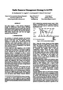
deployment cost of RSs will be much lower than that of BSs. Meanwhile, RS can decode the signal from the source and forward it to the destination. Intelligent resource scheduling and cooperative transmission can be applied to obtain better system performance. Multi-hop relays (MR) have been proposed to enhance cell coverage and user throughput to the traditional cellular systems. In the public deliverable of the EU WINNER project [2], multi-hop relay was introduced to increase the throughput of the boundary users and/or to relay user data to a destination that is out of BS coverage. Within IEEE 802.16 Working Group, IEEE 802.16j Relay Task Group has been devoted to standardize an MR network with the objectives to enhance the system coverage, per-user throughput and/or capacity of the IEEE 802.16 broadband wireless access system. IEEE 802.16j is the only standard body that is currently standardizing a multi-hop relay network. In addition to coverage extension and user throughput enhancement, some results have shown that the system capacity can be improved as well with appropriate deployment of RSs [3-5]. Along this line, this paper investigates the issue of capacity enhancement for the IEEE 802.16j MR network. Firstly, RSs are deployed to have line-of-sight (LOS) to the BS and non-line-of-sight (NLOS) to other interfering RSs. Secondly, radio-resource reuse on different radio links in the same cell is exploited to improve system capacity. Simulation results show that the per-user throughput and system capacity can be substantially improved by the proposed method. II. IEEE 802.16j System Architecture IEEE 802.16j is an amendment to the IEEE 802.16 standard to enable the functionalities of interoperable RSs and BSs. In this section, the key system features of the IEEE 802.16j MR network are overviewed. The basic system architecture considered by IEEE 802.16j is shown in Figure 1(a), where two kinds of radio links are identified: access link and relay link. BS that is capable of supporting multi-hop relay is called MR-BS. The access link is the radio link that originates or terminates at an MS, which is either a downlink (DL) or an uplink (UL), defined in IEEE
ICICS 2007
802.16-2004. The relay link is the radio link between an MRBS and an RS or between a pair of RSs, which can be either uplink or downlink. Following the basic architecture in Figure 1(a), a new frame structure shown in Figure 1(b) is designed [6], where each DL sub-frame and UL sub-frame is divided into access zone and relay zone. The DL/UL access zone is a portion of DL/UL subframe used for access links transmission, and the DL/UL relay zone is a portion of DL/UL sub-frame used for relay links transmission. Note that each DL/UL sub-frame may have more than one relay zone. In order to enable RS operations with no change on the legacy MS specification, two types of RSs have been defined: Non-transparent RS and transparent RS. The non-transparent RS acts as a BS sector [7], therefore the MR-BS has to assign a preamble index to each RS, and the RS will transmit its own preamble, FCH (Frame Control Header) and MAP over the access zone. The frame structure for the non-transparent RS is shown in Figure 1(b). Note that it is not possible for nontransparent RSs to scan and synchronize with each other by the preamble. Because they need to transmit their own preamble at the start of a frame and is not able to receive the preamble transmitted from the MR-BS or other RSs. Therefore, in Figure 1(b) the relay amble (R-amble) located at the end of downlink sub-frame is designed for the purpose of measurement, synchronization and neighborhood discovery over relay links. Note that the R-amble may not be transmitted in each frame for overhead reduction. For the transparent RS, it does not have its own preamble, FCH and MAP. It looks transparent to MS and only relays MS’s data. The frame structure for the transparent RS is similar to Figure 1(b), but the transparent RS will be in receiving mode when the MR-BS transmits its preamble, FCH and MAP. When an MS communicates with a non-transparent RS, it will receive the preamble, FCH, MAP and data burst from the RS. On the other hand, if an MS communicates with a transparent RS, it will receive the data burst from the RS but receive the preamble, FCH and MAP from the MR-BS. Therefore, the transparent RS has to be centralized controlled by the MR-BS to transmit/receive the data burst over the designated sub-channels and symbol times. Note that the MRBS and multiple RSs can serve a particular MS simultaneously so as to increase the received signal quality and obtain cooperative diversity gain. As for the non-transparent RS, it can generate its own FCH and MAP without the instruction from the MR-BS, so that the de-centralized control can be performed to reduce the messaging delay and the messaging overhead over relay links. Meanwhile, a group of RSs may transmit the same preamble, FCH, MAP and data burst, and these RSs will act as a single
virtual station from MS’s point of view [8]. In this case, the MS will not initiate the handover procedure when moving between the grouped RSs and the cooperative diversity gain will be obtained. III.
RS Deployment and Radio-Resource Reuse in Manhattan-like environment In the Manhattan-like environment as the one shown in Figure 2, the shadow fading due to the regulated street layout can be exploited to mitigate the multiple access interference. In the traditional cellular deployment, shadow fading is treated as a negative effect, and a margin is needed in link budget planning to ensure the service availability at the cell boundary. In this paper, firstly RS is deployed to avoid shadow fading as shown in Figure 2(a). By appropriate site selection, RS is deployed to have LOS (line of sight) with the signal source. Secondly, shadow fading is exploited to isolate the interfering signal. For example, in Figure 2(b), RS1 has LOS with its subordinate station MS1. Meanwhile, RS1 has NLOS (non LOS) with MS2. Therefore, the radio link RS1↔MS1 can reuse the radio resource which is allocated the radio link RS2↔MS2, and the interference from RS1 to MS2 is avoided largely by the shadow fading. The proposed RS deployment can be summarized in the following two stages: 1. Deploy RS at the location where it can have LOS to its signal source and to its transmission destination. If LOS is not always guaranteed, select the location where it can have highest LOS probability. 2. After initial deployment in stage 1, adjust the location of each RS to have NLOS condition to its interference sources or its interfering targets. The first deployment stage aims to improve the received strength of the desired signal, and the second stage aims to reduce the interference. Following the aforementioned RS deployment method, the received signal quality can be substantially improved, and the shadow fading can properly isolate the interfering signals transmitted from interference sources. Therefore, within the area surrounded by objects (ex. buildings or hill), the radio resources can be reused by different relay stations without significantly interfering with each other. IV. Simulation Results A. Simulation Environment A downlink two-hop cellular network is simulated in Manhattan-like environment, where 14 RSs are deployed within the coverage of an MR-BS. Total of 19 cells with three sectors per cell are considered. The RS’s locations are as depicted in Figure 3(a), which follows the deployment method proposed in previous section. The MR-BS and RSs are
deployed above rooftop, so that the relay links have line-ofsight (LOS) condition. The access links between MR-BS and MS are assumed to be non line-of-sight (NLOS). For the access links between RS and MS, LOS is assumed if they locate on the same street and the distance is less than 150m. The path-loss and shadow fading models are referenced from the multi-hop relay system evaluation methodology in [9]. The total transmit power of the MR-BS is 45 Watts with 1 km cell coverage, and the RS/MS maximum transmit power are 5 Watts and 0.5 Watts respectively. Two radio resource allocation methods for the MR network are simulated to investigate the potential benefit of the proposed RS deployment method. The conventional method has no radio resource reuse, that is orthogonal radio resource is allocated to relay and access links within a cell. In this case, there is no intra-cell interference. The proposed method is to reuse the radio resource within the same cell, the radio resource for relay links are reused in every sector and the one for access links are reused by every RSs. At the beginning of simulation, MSs are generated by Poisson process and randomly located on the street. During the simulation, the MS moves along the streets and communicates with an RS or the MR-BS based on the received signal quality. The modulation and coding scheme is adjusted on a frame-byframe basis according to signal quality. For each frame, the number of bits successfully received in access links is recorded, and at the end of simulation, the cell throughput is calculated by dividing the number of successfully received bits in access links by the overall simulation time. The more detailed simulation parameters are given in [10]. B. Simulation Results In Figure 4(a), the CDF (Cumulated Distributed Function) of downlink received signal quality is presented for different relay methods and different frequency reuse factors. The simulation results show that the received signal quality can be substantially improved by deploying relay stations. For frequency reuse factor K = 1 , a MS has 23%, 81% and 74% probability to have a received Eb/(I0+N0) higher than 20 dB in the cases of no relay, conventional relay, and the proposed relay methods, respectively. It means that the received signal quality is improved by deploying RSs, which is mostly achieved by the lower propagation loss from serving station to MS. On the other hand, if we draw a horizontal line at CDF=10% and compare the curves with K = 1 . It shows that a mobile station has 10% probability to have signal quality lower than 4dB, 15dB and 11dB for the case with no relay, conventional resource allocation method and proposed resource allocation method, respectively. If the coverage planning criterion is to ensure mobile station has 90% probability to have signal quality better than 4dB, the
conventional method and proposed method can lead to additional 11dB and 7 dB margin in link budget for coverage extension. The downlink cell capacity is presented in Figure 4(b), which shows that the proposed resource allocation method and RS deployment method can lead to substantial capacity improvement than conventional method and the case with no relay. For two-hop case, a data bit is transmitted from BS to RS in 1st hop and RS to MS in 2nd hop in different time, so only one effective bit is received by MS. Therefore, the results show that the conventional method has smaller cell capacity because all traffic in relay links shall be treated as overhead, and the improvement by higher transmission rate cannot break even with the lost on radio resources for relay links. The conventional method has -4.81%, -27.63% and -33.92 cell capacity with respect to the case with no relay for reuse factors K = 1, 3 and 7 , respectively. On the other hand, the proposed resource reuse method along with RS deployment method can achieve 116.4%, 68.33% and 56.03% capacity gain for reuse factors K = 1, 3 and 7 , respectively. The cell capacity is improved because radio resources are reused in different relay links and access links within each cell and the proposed RS deployment method also utilize the severe shadow fading effect to isolate the interfering signals. In Figure 5(a), the CDF of uplink transmission power for MS is presented. Because the power control is considered in uplink transmission, therefore, the reduction on propagation loss by RS deployment will lead to lower transmit power. For K = 1 , MSs have the probabilities 36.43%, 74.23% and 63.10% to consume the transmission power lower than 10dBm for the case of no relay, conventional method, and the proposed method, respectively. According to the better propagation condition and lower propagation loss, the uplink transmission power can be substantially reduced by RS deployment. The uplink capacity is presented in Figure 5(b), which is defined as the effectively received bits at MSs within each cell in uplink access zone. Compared with the conventional method, it shows that 2.54%, 35.84% and 44.11% capacity gain can be achieved by the proposed resource reuse method for the cases of K = 1 , 3 and 7, respectively. On the other hand, degradation on system capacity is observed in the MR network due to additional resource used for multi-hop transmission for the case of K = 1 . Ⅴ. Conclusion This paper investigates the issues of RS deployment and radio-resource reuse in the IEEE 802.16j multi-hop relay network. By deploying RSs at locations that have LOS to the signal source and NLOS to the interference sources, radio resource is reused to improve the system capacity. Simulation
results in the Manhattan-like environment are given to illustrate the attainable improvement.
REFERENCES [1] Recommendation ITU-R M.1645, “Framework and overall objectives of the future development of IMT-2000 and systems beyond IMT-2000,” International Telecommunication Union, Jun. 2003. [2] A. Adinoyi et al, “Description of Identified new Relay Based Radio Network Deployment Concepts and First Assessment by Comparison against Benchmarks of well known Deployment Concepts using Enhanced Radio
Interface
Technology,”
IST-2003-507581
WINNER
D3.1,
Nov.2004. https://www.ist-winner.org/ [3] J. Cho and Z. J. Haas, “On the Throughput Enhancement of the Downstream Channel in Cellular Radio Networks Through Multihop Relaying,” IEEE Journal on Selected Area in Communications, Vol.22, No.7, pp.1206-1219, Sep. 2004. [4] I. K. Fu, W. H. Sheen, C. L. Hsiao and C. C. Tseng, “System Performance of Relay-based Cellular Systems in Manhattan-like Scenario,” IEEE C80216mmr-05/041, Nov. 2005. [5] I. K. Fu, W. H. Sheen, C. L. Hsiao and C. C. Tseng, “Reverse Link Performance of Relay-based Cellular Systems in Manhattan-like Scenario,” IEEE C80216mmr-06/004, Jan. 2006. [6] M. Hart et al, “Baseline Document for Draft Standard for Local and Metropolitan Area Networks – Part 16: Air Interface for Fixed and Mobile Broadband Wireless Access Systems, Multihop Relay Specification,” IEEE 802.16j-06/026r3, Apr. 2007. [7] P. Wang et al.,“Fixed and Nomadic Relay Station Preamble Segment Assignment Scheme,” IEEE C802.16j-07/040r8, Mar. 2007. [8] H. Zhang et al,, “Virtual Relay Grouping Concept to Support RSs Sharing
Fig.1 (a) The system architecture and (b) the frame structure for IEEE 802.16j multi-hop relay network
the Same Preamble,” IEEE C802.16j-07/144r7, Mar. 2007. [9] M. Hart et al., “Multi-hop Relay System Evaluation Methodology (Channel Model and Performance Metric),” IEEE 802.16j-06/013r3, Feb. 2007. [10] I. K. Fu, W. H. Sheen and F.-C. Ren, “Shadow-assisted Resource Reuse for Relay-augmented Cellular Systems in Manhattan-like Environment,” International Journal of Electrical Engineering, pp.11-19, Vol. 14, No. 1, Feb.2007.
Fig.2 The proposed RS deployment method: (1) to have LOS with signal source and (2) to have NLOS with interference source
Fig.3 (a) Simulation environment and (b) the location of interfering cells Fig.5 (a) The CDF of uplink MS transmit power and (b) uplink cell capacity
Fig.4 (a) CDF of downlink received signal quality and (b) the downlink cell capacity