DEPLOYMENT-DRIVEN SECURITY CONFIGURATION FOR VIRTUAL NETWORKS Ramaswamy Chandramouli Computer Security Division, Information Technology Laboratory National Institute of Standards & Technology Gaithersburg, MD, USA
[email protected]
ABSTRACT Virtualized Infrastructures are increasingly deployed in many data centers. One of the key components of this virtualized infrastructure is the virtual network – a software-defined communication fabric that links together the various Virtual Machines (VMs) to each other and to the physical host on which the VMs reside. Because of its key role in providing connectivity among VMs and the applications hosted on them, Virtual Networks have to be securely configured to provide the foundation for the overall security of the virtualized infrastructure in any deployment scenario. The objective of this paper is to illustrate a deployment-driven methodology for deriving a security configuration for Virtual Networks. The methodology outlines two typical deployment scenarios, identifies use cases and their associated security requirements, the security solutions to meet those requirements, the virtual network security configuration to implement each security solution and then analyzes the pros and cons of each security solution.
KEYWORDS Virtualized Infrastructure, Virtual Machine, Virtual Network, Security Configuration, Software Defined Network
1. INTRODUCTION Virtualized infrastructures are increasingly deployed in many data centers, driven by cost, efficiency, scalability and in some cases security considerations. The term virtualized infrastructure, in the context of this paper, includes the following: the physical host or server that is virtualized (called Virtualized Host), the Hypervisor software, the Virtual Machines (VMs) residing on a virtualized host, the software-defined virtual network that is configured inside a virtualized host, middleware and management tools specific to the virtualized environment, the hardware/software components relating to storage, the common networking components of the data center such as physical Network Interface Cards (physical NIC), switches (physical and virtual), routers, firewalls, load balancers, application delivery controllers etc. One of the key components of this virtualized infrastructure is the virtual network [1] – a software-defined communication fabric that links together the various Virtual Machines (VMs) to each other and to the physical host on which the VMs reside. The VMs are instantiated and managed by a piece of software called “Hypervisor” which in turn is installed in many instances Natarajan Meghanathan et al. (Eds) : NeTCoM, CSIT, GRAPH-HOC, SPTM - 2014 pp. 01–13, 2014. © CS & IT-CSCP 2014 DOI : 10.5121/csit.2014.41301
2
Computer Science & Information Technology (CS & IT)
directly on a physical computing hardware. We will refer to the physical computing hardware on which the hypervisor is installed as Virtualized Host. It is in fact the hypervisor that provides the API and the functional code necessary to define and configure a virtual network linking the various VMs with each other and to the virtualized host where they (Hypervisor and the VMs) all reside. Since the term “Virtual Network” in the context of networking as a whole is an overloaded term, it is good to clarify its semantics in the context of the virtualized infrastructure discussed in this paper. In our context, the term virtual network encompasses the two aspects: (a) Software-enabled NIC Virtualization and (b) Data path Virtualization. A brief explanation of these two aspects follows: Software-enabled NIC Virtualization [2]: Here a physical Network Interface Card (pNIC) in a virtualized host is shared among many Virtual Operating Systems (OSs) (called Guest OS, Virtual Machines or Domains depending upon the product offering). This sharing is possible through a software-defined artifact called Virtual NIC (or vNIC), which is a software emulation of a physical NIC. Each vNIC is defined within a Virtual OS and the latter is therefore called the client of vNIC. Each vNIC may be assigned its own dedicated IP and MAC addresses. If the Virtual OSs (clients of vNIC) run a server software (e.g., Web Server, DNS Server or Firewall), they are also referred to as “Virtual Servers”. The bridging of these vNICs or multiplexing of the traffic from different vNICs (and hence different VMs or Virtual Servers) for achieving the goal of sharing physical NICs is achieved using a software-defined switch called virtual switch (vSwitch in some product offerings) [3]. Links between vNICs and virtual switches are softwareemulated links and so are the links between virtual switches and physical NICs (the later are also called uplinks). Data path Virtualization [2]: The software-emulated links created by NIC virtualization above can be virtualized using a capability in the virtual switches. This type of link virtualization is different from virtualization of links found in physical channels (using multiplexing or creation of virtual circuit) where virtualization happens at the channel. In data path virtualization, virtualization of links happens at the network node level (i.e., virtual switch). These virtual switches (vSwitches) have the capability to define dynamic multiple port groups within it (just like ports in a physical switch). These port groups are tagged with what are known as Virtual LAN (VLAN) IDs [4]. These tags or labels are used by virtual switches to create multiple virtual links (data paths). Thus VLAN tags achieve two different objectives – to share the same infrastructure (e.g., the LAN infrastructure or communication channel) as well as creating data paths in the broadcast domain. In Summary, the virtual network in the context of this paper is a “software-emulated network which generates traffic that is injected into the real world through a non-virtual/non-emulated physical NIC” [2] and has the following building blocks: • • • • •
Virtual Servers (Clients of vNICs) Virtual NICs (vNICs) Virtual Switches (vSwitch) Virtual Links and Physical NICs (pNICs).
In addition to the above components, we also include external physical switches/routers attached to virtualized hosts (more specifically to the physical NICs of the hosts) also under the umbrella of the “virtual network” since they play a role in configuration of the virtual network (e.g., interVLAN routing). Other components such as VLAN ID/Port Group (in the Virtual Switch), Software-defined firewalls & IDS/IPS installed as Virtual Security Appliance (VSA), Load Balancers etc (sometimes packaged as Virtual Appliances) are also included since they are artifacts used in a virtual network configuration as well.
Computer Science & Information Technology (CS & IT)
3
Having settled on the semantics for the virtual network, let us turn our attention to the role of virtual networks in a virtualized infrastructure. While the hypervisor kernel provides the processlevel isolation for the VMs, it is the virtual network that provides the connectivity between the VMs and the applications hosted on them. Hence, secure configuration of the virtual network forms the foundation for the security of the entire virtualized infrastructure. Two significant deployment scenarios for a large virtualized infrastructure are: •
Hosting Multi-tier applications (with extensive connectivity between components containing various application tiers) with a large user base, large volume of data or high volume of transactions or combination of all three
•
Offering an Infrastructure as a Service (IaaS) public cloud service.
In this scenario, VMs belonging to different cloud service clients could be potentially coresidents in a single virtualized host of the infrastructure. It must be emphasized that the two deployment scenarios stated above are not mutually exclusive. For example, a 3-tier application (consists of Web Server, Application Server & Database Server tiers) may be hosted on three different groups of VMs either by the enterprise itself (as part of its internal IT resources) or by a cloud service client (if the virtualized infrastructure is used for offering a public cloud service). In the former case, the virtualized infrastructure and all the VMs are owned by the enterprise while in the latter case, the ownership of the VMs is with the cloud service client while the virtualized infrastructure is owned by the cloud service provider. The objective of this paper is to illustrate a methodology for obtaining a secure virtual network configuration based on deployment scenarios cited above. The methodology is based on identifying the typical set of use cases in the deployment scenarios. Section 2 lists the steps of the methodology and identifies the various use cases. Section 3 is the core material for this paper as it describes the steps of the methodology used to derive security configuration for a virtual network and also analyzes the pros and cons of the underlying security solution. Section 4 outlines the benefits of the methodology.
2. METHODOLOGY FOR DERIVING VIRTUAL NETWORK SECURITY CONFIGURATION The methodology for deriving a virtual network security configuration has the following key steps: •
STEP 1: Identify the key use cases that result from the deployment scenarios stated in the previous section. We consider only use cases that have an impact on virtual network configuration parameters and identify those that are not within the scope of the methodology.
•
STEP 2: For each chosen use case, identify the associated security requirements and a security solution that will meet the requirements.
•
STEP 3: Identify and describe the virtual network security configuration operations that will implement the security solutions and also analyze the pros and cons of those security solutions.
4
Computer Science & Information Technology (CS & IT)
2.1 Choice of Use Cases in Virtualized Infrastructure Deployments As already mentioned, we consider here only those use cases that are relevant from the virtual network standpoint. Before identifying those use cases, we first provide here certain use cases that get a lot of attention in deployments involving virtualized infrastructures [5], but do not impact the virtual network configuration parameters. These use cases therefore are not considered within the scope of our methodology. • • • • •
Building a VM image, versioning of VM images, maintaining the integrity of the VM images both during storage and while using them for instantiating VM instances. Configuring the VM OS (or Guest OS) Configuring Endpoint (Virus & Malware) protection for VMs Providing Access Protection for accessing VMs from an external network Comprehensive Data Protection (Data in VM definition files and Application Data)
We now identify the typical set of use cases that may require virtual network configuration for their secure implementation. All these use cases by and large pertain to one or both of the two key components of the virtualized infrastructure: the Hypervisor and the VMs. They are: • •
Managing the Hypervisor and the virtual network it spawns (e.g., VMs, Virtual Switches/Port Groups/VLANs etc) (MH) Providing Selective Isolation/Connectivity between various applications/VMs (VM-CO)
3. IMPACT OF USE CASE OPERATIONS ON VIRTUAL NETWORK SECURITY CONFIGURATION In this section, we describe for each use case, the associated security requirements, the security solutions that will meet the security requirements and the virtual network security configuration operations that will implement each security solution and also analyze the pros and cons of each of the security solutions.
3.1 Management of the Hypervisor (MH) The set of management commands sent to the hypervisor includes those that are needed for running a hypervisor as well those that are needed to create an application hosting environment (Provisioning VM instances & Creating a Virtual Network configuration to support them). Specifically these are the broad categories of commands sent to the hypervisor. •
Commands needed to set the hypervisor’s functional parameters (e.g., the CPU scheduling algorithm it uses)
•
The commands needed to define the topology of the virtual network (creation of virtual switches, ports within each virtual switch and connections between vNICs provided through virtual switches as well as connections from ports/virtual switches to physical NICs of the virtualized host)
•
Commands relating to operations on VMs (e.g,, Start, Stop & Pause VMs, Migrate a VM from one Virtualized Host to another etc – these are sometimes called VM lifecycle operations)
In some hypervisor architectures, the functions relating to VM Management (VM Lifecycle operations) are offloaded to a dedicated, security hardened VM (sometimes called Management VM). Regardless of this architectural variation, all hypervisors have an interface (called
Computer Science & Information Technology (CS & IT)
5
management interface) for sending these management commands. The obvious security requirements (SR) considering the sensitive nature of the operations performed by the invocation of these commands are: •
MH-SR-1: The sources from which these commands originate must be restricted to some trusted sources
•
MH-SR-2: The management commands must be sent securely - protecting their integrity and sometimes confidentiality.
•
MH-SR-3: The communication channels (data paths) carrying these management commands must be logically isolated from channels carrying other types of traffic such as the data/application related traffic.
Out of the three security requirements stated above, MH-SR-1 is met by restricting the set of users who are authorized to invoke the hypervisor management commands to some trusted administrators and by restricting the origin of the command packets to designated administrative LANs within the enterprise [6]. For accomplishing this latter objective, a dedicated softwaredefined firewall may have to be installed exclusively for protecting the management interface. MH-SR-2 is met by establishing a secure communication protocol such as SSH with the management interface and sending the management commands digitally signed and/or encrypted [6]. Hence the only security requirement here that has to be met through a virtual network-based security solution is MH-SR-3. The security solution (SS) for obtaining an isolated communication channel exclusively dedicated to management commands (requirement MH-SR3) is: •
SS-1: Use a dedicated virtual network segment for sending all management commands to the Hypervisor.
The virtual network security configuration operations to implement the above security solution are: •
VN-SC-OP-1: Dedicate a VLAN for carrying just the hypervisor management traffic. This is accomplished by creating a port of connection type console or kernel (depending upon the hypervisor) on a virtual switch of the hypervisor and assigning a VLAN ID to that port and associating the management interface (along with its IP address) with it. A dedicated VLAN on a kernel-type port is also the preferred configuration option for supporting VM Migration commands.
•
VN-SC-OP-2: An added security assurance, in the pursuit of isolating management traffic from all other traffic into the hypervisor, can be obtained by having a virtual switch (vSwitch) just dedicated for defining the management VLAN with no other connections.
Analysis of the security solution: A dedicated virtual network segment is just one of the three security solutions for managing the hypervisor. It has to be augmented with administrator access control, interface-protecting firewall and a secure communication protocol.
3.2 Providing Selective Isolation/Connectivity between various applications/VMs (VM-CO) In the previous section, the need for isolating the management traffic from the application traffic was addressed. There is also a need to provide selective isolation among traffic pertaining to
6
Computer Science & Information Technology (CS & IT)
different applications running in VMs. This need is closely aligned with the two deployment scenarios outlined in Section 1 as follows: •
Multi-tier Applications: The enterprise may run multiple multi-tier applications of different sensitivity levels in VMs based on the type of data processed or the functions/operations performed. In some instances, VMs need to be isolated based on the Line of Business (LOB) and/or functional departments.
•
Multiple Tenants on a Host: VMs belonging to different cloud service clients must be logically isolated from one another to protect the integrity of data and applications hosted on them. In many instances, there may be the need to provide logical isolation among VMs belonging to the same cloud service client.
After isolating the VMs by the nature of the application (or LOB or Functional Department) or cloud service client, it may be found that some business processes require that applications in the VMs of one department/LOB may need to communicate or interact with applications in VMs of other departments/LOBs. These twin security requirements (Selective Isolation and Connectivity) are stated as follows: •
VM-SR-1: Traffic going into/emanating from VMs running sensitive applications must be isolated from traffic pertaining to non-sensitive applications. Traffic among VMs belonging to a Line of Business (LOB) or a functional department (e.g., Accounting, Engineering etc) or a cloud service client must be isolated from corresponding traffic from other LOBs, functional departments or cloud service clients respectively.
•
VM-SR-2: Communication between VMs belonging to different logical groups (Application Profile, LOB or Functional Department) must be enabled in some instances but should be governed by a security policy.
The various security solutions that can meet the above requirements are: •
SS-2: Virtual Network Segmentation using VLAN IDs
•
SS-3: Virtual Network Segmentation using VLAN IDs with Software Defined Network (SDN) support
•
SS-4: Control of Network traffic using Firewalls installed as Virtual Security Appliances (VSA)
•
SS-5: Control of Network traffic using Virtual Switches with SDN Support
A description of the above security solutions, the virtual network security configuration operations needed to implement each of the solutions and performance characteristics of each of these solutions are given below: 3.2.1
Virtual Network Segmentation using VLAN IDs
Isolation of traffic among VMs residing in a virtualized host (or in different hosts) is achieved by segmentation of the virtual network and connecting the VMs (or Virtual Network Interface Cards (vNICs)) to the corresponding port in the virtual switch tagged with the ID of that virtual network segment. A common technology used for this purpose is the Virtual Local Area Network or VLAN. Since the VMs in a virtualized host are connected to virtual switches, the ports in the virtual switches are tagged with VLAN IDs and the VMs designated for a particular VLAN
Computer Science & Information Technology (CS & IT)
segment are assigned (connected) to the corresponding virtual switch port. operations for achieving the requisite virtual network security configuration are:
7
The necessary
•
VN-SC-OP-3: Identify the set of VMs that belongs to a specific cloud service client (tenant) or Line of Business (LOB) or functional department and assign them to a new VLAN (VLAN ID). Also identify the set of virtualized hosts that are targets for hosting them.
•
VN-SC-OP-4: Define a new VLAN using the interface that your LAN management software provides.
•
VN-SC-OP-5: Define/Identity virtual switches on the target hosts (for identified VMs), define/identify ports on those virtual switches and associate the new VLAN ID with those switch ports. This type of ports is simply called VM portgroup in some hypervisors. Connect the identified VMs (or the vNIC) to those portgroups.
•
VN-SC-OP-6: The previous operation has configured the virtual switches inside the virtualized hosts with the new VLAN. The same VLAN has to be configured on the external physical switches connected to those virtualized hosts. This requires four operations: (1) The new VLAN ID has to be added to the external switch’s VLAN database; (2) At least one of the ports on that external switch must be enabled to support traffic carrying that VLAN ID; (3) The port enabled for that VLAN ID must be connected to the physical NIC of the virtualized host, and finally (4) that particular physical NIC should be connected as the uplink port for the virtual switch on which the new VLAN ID is defined.
This establishes a communication path from the vNIC of the VM to the virtual switch’s port (to which the former is connected) and through its (the virtual switch) uplink port to the virtualized host’s physical NIC and on to the external physical switch. One requirement needed for this configuration is that the port on the external switch on which VLAN is enabled should be configured as a trunk port (capable of receiving/forwarding traffic belonging to multiple VLANs). Firewall rules can then defined on this external switch to provide selective connectivity between different VLANs. Analyzing the above security solution, we find the following limitations. They are [7]: •
There is a limit to the number of VLAN IDs that can be used (the figure is 4096)
•
Configuring the virtual switches inside the virtualized hosts (where identified VMs are hosted) as well as physical switches connected to the virtualized hosts for one or more VLANs is a manual, time-consuming and error-prone process, part of which may have to be repeated if application profile of VMs change.
•
To enforce restrictions on inter-VLAN communication, the enforcement point is a physical firewall or the physical switch. This requires routing all traffic originating from or coming into a VM to the physical NIC of the virtualized host and on to the trunk port of a external physical switch, thus increasing the latency of communication packets with consequent increase in application response times.
3.2.2
Virtual Network Segmentation using VLAN IDs with SDN support
Before looking at this security solution, it would be good to review the architectural concepts underlying SDN. SDN is an architectural concept that enables direct programmability of
8
Computer Science & Information Technology (CS & IT)
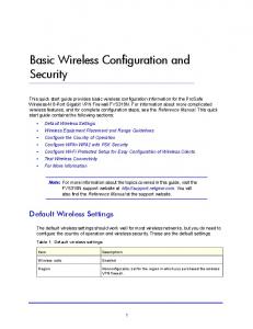
networks through open-source Standards-based APIs [8]. This capability is enabled by dividing the functionality of a network device such as a switch or router into two distinct layers – the data plane and control plane. The control plane is implemented by a software called SDN controller and defines how data flows (i.e., how network messages/packets are forwarded and routed) while the data plane performs the basic task of storing/forwarding packets based on entries in the forwarding table. The SDN controller is often centralized (so that it controls data forwarding functions of multiple data planes each associated with a network device) and communicates with data planes through a standardized API (e.g., OpenFlow [9]). The interface to the data plane (which in the SDN architecture is essentially is a network device with SDN support (such as a SDN switch) is also called “Southbound Interface”. Similarly the SDN controller also can be implemented to have an open interface, called the “Northbound Interface”. An architectural diagram of a SDN is given in Figure 1 below:
Figure 1. SDN High Level Architecture
The SDN architecture can be leveraged to automate the creation of VLANs for isolating traffic among VMs in the following way. First, the virtual switches that can be defined using the hypervisor APIs should be capable of supporting SDN capabilities. An example is the open vSwitch [10]. Secondly, there should be a SDN controller that can communicate with and control all SDN supported virtual switches. With this set up, the Northbound interface exposed by SDN controller can be used to send in commands to create the necessary VLANs (operation VN-SCOP-4) as well as send in information regarding VMs and their locations (virtualized hosts and SDN virtual switches) pertaining to each VLAN. This information is used in the SDN controller to generate commands, that is sent through the Southbound Interface for: (a) creating the necessary port groups/VLAN tags on SDN supported switches and (b) connect the VMs to those switch ports (operation VN-SC-OP-5). Similarly the tasks involved in VN-SC-OP-6 can also be automated if the external physical switch is also a SDN switch. This security solution presents the following advantages: •
Due to standardized interfaces and pre-programmed scripts, the creation of VLAN and enabling the connectivity of VMs to the designated VLAN are automated thereby reducing/eliminating the errors that could creep in manual configuration. The relevant
Computer Science & Information Technology (CS & IT)
9
interfaces are: (a) SDN controller interface (Northbound Interface) and (b) SDN supported virtual switch interface (Southbound Interface). •
Similarly, the VLAN reconfiguration necessitated by VM migrations or change in application profiles of VMs can also be automated using SDN interfaces.
•
The VLAN ID limit of 4096 imposed by IEEE 802.1Q standard can be overcome by creating packet forwarding rules in SDN controller based on MAC addresses to be placed on virtual switches
3.2.3. Control of Network traffic using Firewalls installed as Virtual Security Appliances In the virtualized infrastructure, network security using firewalls can be implemented in two ways: (a) installing a firewall in each of the VMs to be protected or (b) installing a firewall at the hypervisor-level to enforce traffic control rules for all VMs in that virtualized host. The latter solution uses the hypervisor’s Virtual Machine Introspection (VMI) API. The configuration operations for this solution are: VN-SC-OP-7: Install a firewall as a Virtual Security Appliance (VSA) inside a hardened VM. This appliance has the ability to enforce traffic restrictions on traffic going into any VM by virtue of its access to the hypervisor’s VMI API. The packets for enforcement are fed into it by a hypervisor kernel module that forwards all or selected (based on a set of rules) packets coming into the vNIC of every VM in the virtualized host [11]. The performance characteristics of this security solution are: •
It does not consume the valuable CPU cycles in individual VMs which could otherwise be used for running the business applications.
•
All policies needed for the firewall can be defined centrally in the Virtual Infrastructure Management server and then pushed in to the firewall VSA running in several virtualized hosts.
•
Firewall VSAs are capable of supporting sophisticated logic for traffic control rules such as the ability to define security groups based on customized criteria.
3.2.4. Control of Network traffic using Virtual Switches with SDN Support To implement this solution, the virtualized infrastructure should have a network with SDN capabilities as described in 3.2.2. In this solution, traffic control using firewall like rules which only allow packets based on the following values – A specific protocol (TCP or UDP), from port, to port, A single IP address or range of IP addresses can be implemented directly on virtual switches in a hypervisor instead of in a virtual security appliance (VSA) [12]. A set of VMs is associated with a Security Group. A traffic control rule can be associated with one or more Security Groups. A VM instance can also be associated with multiple Security Groups. Using these combinations, the set of traffic control rules applicable for a particular VM instance (say VM1) can be identified. Let us assume for simplicity that VM1 is associated with a single Security Group (SG1). An example of a traffic control rule (SG1-R1) associated with this Security Group SG1 is given in Table 1. This rule allows TCP traffic on port 6001 from any VM in the IP address range 10.10.2.1 to 10.10.2.4 into the VM instance VM1. Let us also assume that the VM instance VM1 is launched with an IP address of 10.10.2.27. Let us also assume that VM instances within the IP range specified in Table 1 is connected to the
10
Computer Science & Information Technology (CS & IT)
same virtual switch as VM1. Hence to install incoming traffic control rules for VM instance VM1 on the virtual switch to which it is connected, the configuration operations are as follows: •
VN-SC-OP-8: The Virtualized Infrastructure Management server provides to the SDN controller through its Northbound interface the following information for VM instance VM1: VM1’s IP address (10.10.2.27), the virtual switch (vS1) to which VM1 will be connected, the Security Groups associated with VM1 (SG1) and the associated traffic control rules (SG1-R1). TABLE 1. Security Rule (SG1-R1) for Security Group (SG1) Field Protocol From Port To Port Source
•
Value TCP 6001 6001 10.10.2.1 – 10.10.2.4
VN-SC-OP-9: Now the SDN controller has the task of connecting VM instance VM1 to virtual switch vS1 and to implement the security group rule (SG1-R1) on the switch vS1 (since the VM instance VM1 belongs to security group SG1). To accomplish the latter task, the SDN controller converts the SG1-R1 rule into the format of SDN-standard rule (e.g., an OpenFlow rule) and installs them on the virtual switch vS1 to which the VM instance VM1 is connected. This operation is repeated for every VM instance added to the Security Group SG1.When a new rule (SG1-R2) is added to the Security Group SG1, the virtualized management infrastructure server communicates this information to SDN controller. The SDN controller generates the list of VM instances belonging to the Security Group SG1 and installs the new rule on the virtual switch that hosts each instance. Similarly, if a rule is removed from SG1, the SDN controller will uninstall (delete) the corresponding traffic flow rules for each VM instance from their respective virtual switches.
We can clearly see the advantages of the traffic control implemented on virtual switches instead of in firewalls (installed as virtual security appliance) as follows: •
It avoids the unnecessary forwarding of all traffic destined for all VMs to the security VM hosting the virtual security appliance-based firewall.
•
Thanks to programmable scripts within the SDN controller, the virtual network configuration operations required due to addition and deletion of rules or VMs to Security Groups can be completely automated.
4. BENEFITS & CONCLUSIONS This paper has outlined a methodology for deriving security configuration of a virtual network in a virtualized infrastructure for two deployment scenarios. The security configurations are implementations of security solutions which meet the security requirements for use cases of the two deployment scenarios. We have also performed an analysis of those security solutions. The artifacts generated by the methodology are summarized in Table 2 below. The methodology has the following two security assurance benefits: •
The first benefit is that, the use-case/security requirements/security solution/virtual network configuration trajectory adopted in the approach provides automatic traceability
Computer Science & Information Technology (CS & IT)
11
of the any configuration setting to a use case/security requirement. It thus implicitly provides a logical basis for versioning of a particular virtual network configuration. It also provides the validity for modifying, removing or enhancing a virtual network security configuration based on the following: (a) A use case has been dropped or modified (b) A new threat scenario has necessitated the need for additional security requirements for an existing use case. •
The second benefit is that, the analysis of the security solutions underlying a particular virtual network security configuration helps to ensure that the resulting configuration meets the security requirements/objectives, are appropriate for the virtualized infrastructure context and use the state of practice technology.
The role of virtual networks in ensuring the security of the overall virtualized infrastructures is likely to grow with adoption of technologies like: (a) Distributed virtual switches (as opposed to switches specific to a virtualized host), (b) More SDN capabilities for virtual switches, and (c) Attestations of boot integrity for VMs (in addition to hypervisor modules). Being a use-case driven methodology, it has the flexibility and scalability to be applied in these emerging virtualized infrastructure environments as well. TABLE 2. SUMMARY OF VIRTUAL NETWORK SECURITY CONFIGURATION Use Case
Security Requirements
Security Solution & its Analysis
Virtual Network Security Configuration
1. Management of the Hypervisor and the Virtual Network it spawns (MH)
(a)Restricting commands to trusted sources (b) Protecting the Integrity & Confidentiality of Commands (c) Restricting Management Traffic to dedicated channels
Dedicated Virtual Network Segment: (a) Not a stand- alone solution. Must be augmented with administrator access control, firewall and secure communication protocol
2. Selective Isolation/Connectivity between existing applications/VMs (VM-CO)
(a)Isolating Traffic among Logical VM Groups (LOB, Functional Department or Cloud Service Client) (b)Controlled Communication between logical VM Groups based on a security policy (which translates to a set of Traffic Control Rules)
Virtual Network Segmentation using VLAN IDs: (a)VLAN ID Limitation (b) Manual, Errorprone process (c) Communication latency as all traffic is routed to an external switch
(a) Assign a VLAN ID on a Service Console or Kernel type port of a virtual switch and associate only the management interface with it. (b) Configure no other traffic on that virtual switch (dedicate that virtual switch for management traffic) (a)Select a new VLAN ID and associate it with a port on vSwitch (b) The new VLAN ID is added to the external switch’s VLAN database and enabled on one of its ports (c) Define firewall rules on the switch for InterVLAN communication Same as the previous row except that all VLAN configuration operations can be performed by executing scripts using Northbound & Southbound interfaces of SDN
Virtual Network Segmentation using VLAN IDs with SDN support VLAN configuration and re-configuration can be totally automated
12
Computer Science & Information Technology (CS & IT) Control of Network traffic using Firewalls installed as Virtual Security Appliances (a)Communication Traffic policy defined centrally and implemented uniformly in all virtualized hosts (b) Security Groups can be defined based on an customized criteria and used in firewall rules (c) All traffic coming into all VMs must be routed to the VM hosting the firewall VSA potentially affecting application response times Control of Network traffic using Virtual Switches with SDN Support: (a)Avoids unnecessary traffic generated due to the need to route all traffic to VM hosting the firewall (b) Automated propagation of changes to the security rule set to all affected VM instances
(a)Install a firewall as a Virtual Security Appliance (VSA) inside a hardened VM (b)Link it to a kernel module that forwards all packets destined for any VM
(a) For a given Security Group, the information about its constituent VMs , as well as Traffic control rules are sent to SDN controller through Northbound Interface (b) SDN controller installs the rules on virtual switches connected to those VM instances through its Southbound interface
REFERENCES [1]
Virtualization Overview [On-line] Available: http://www.vmware.com/pdf/virtualization.pdf [Retrieved: June 2014] [2] A. Wang, M.Iyer, R.Dutta, G.Rouskas, and I. Baldine, “Network Virtualization: Technologies, Perspectives, and Frontiers,” Journal of Lightwave Technology, Vol. 31, No. 4, Feb 15, 2013 [3] VMware Virtual Networking Concepts, [On-line]. Available: http://www.vmware.com/files/pdf/virtual_networking_concepts.pdf [Retrieved: June 2014] [4] IEEE 802.1Q Virtual LANs (VLANs), [On-line]. Available: http://www.ieee802.org/1/pages/802.1Q.html [Retrieved: June 2014] [5] R. Chandramouli, “Analysis of Protection Options for Virtualized Infrastructures in Infrastructure as a Service Cloud,” Proceedings of the Fifth International Conference on Cloud Computing, Venice, Italy, May 2014. [6] “Amazon Web Services: Overview of Security Processes,” March 2013, http://aws.amazon.com/security/ [Retrieved: February, 2014] [7] Q. Chen, et al, “On State of the Art in Virtual Machine Security”, IEEE Southeastcon, 2012, pp. 1-6. [8] Open Networking Foundation,[On-line]. Available: http://www.opennetworking.org [Retrieved: June 2014] [9] OpenFlow, [On-line].Available: http://www.openflow.org [Retrieved: June 2014] [10] Open vswitch, [On-line]. Available: http://openswitch.org [Retrieved July 2014]
Computer Science & Information Technology (CS & IT)
13
[11] “The Technology Foundations of VMware vShield,” [On-line] Available: http://www.vmware.com/files/pdf/techpaper/vShield-Tech-Foundations-WP.pdf [Retrieved: April, 2014] [12] G. Stabler, et al, “Elastic IP and security groups implementation using OpenFlow,” Proceeedings of the 6th International Workshop on Virtualization Technologies in Distributed Computing, Deft, Netherlands, 2012 .