Depth-based defocus map estimation using off-axis apertures Eunsung Lee, Eunjung Chae, Hejin Cheong, Semi Jeon, and Joonki Paik∗ Image Processing and Intelligent Systems Laboratory Graduate School of Advanced Imaging Science, Multimedia, and Film Chung-Ang University, Seoul, South Korea ∗
[email protected]
Abstract: This paper presents a depth-based defocus map estimation method from a single camera with multiple off-axis apertures. The proposed estimation algorithm consists of two steps: (i) object distance estimation using off-axis apertures and (ii) defocus map estimation based on the object distance. The proposed method can accurately estimate the defocus map using object distances that are well-characterized in a color shift modelbased computational camera. Experimental results show that the proposed method outperforms the state-of-the-art defocus estimation methods in the sense of both accuracy and the estimation range. The proposed defocus map estimation method is suitable for multifocusing, refocusing, and extended depth of field (EDoF) systems. © 2015 Optical Society of America OCIS codes: (100.2000) Digital image processing; (110.1758) Computational imaging; (100.6890) Three-dimensional image processing; (100.2960) Image analysis.
References and links 1. W. You, K. Michael, and M. Yu, “Efficient total variation minimization methods for color image restoration,” IEEE Trans. Image Process. 17(11), 2081–2088 (2008). 2. V. Maik, J. Shin, and J. Paik, “Regularized image restoration by means of fusion for digital auto focusing,” in Proceedings of Computational Intelligence and Security (Springer, 2005), pp. 928–934. 3. P. Favaro and S. Soatto, “A geometric approach to shape from defocus,” IEEE Trans. Pattern Anal. Mach. Intell. 27(3), 406–417 (2005). 4. P. Favaro, S. Soatto, M. Burger and S. Osher, “Shape from defocus via diffusion,” IEEE Trans. Pattern Anal. Mach. Intell. 27(3), 518–531 (2008). 5. S. Pertuz, D. Puig, M. Garcia, and A. Fusiello, “Generation of all-in-focus images by noise-robust selective fusion of limited depth-of-field images,” IEEE Trans. Image Process. 27(3), 1242–1251 (2013). 6. Y. Tai and M. Brown, “Single image defocus map estimation using local contrast prior,” in Proceedings of International Conference on Image Processing (IEEE, 2009), pp. 1798–1800. 7. S. Zhuo and T. Sim, “Defocus map estimation from a single image,” Pattern Recogn. 44(9), 1852–1858 (2011). 8. C. Shen, W. Hwang, and S. Pei, “Spatially-varying out-of-focus image deblurring with L1-2 optimization and a guided blur map,” in Proceedings of International Conference on Acoustics, Speech and Signal Processing (IEEE, 2012), pp. 1069–1072. 9. C. Willert and M. Gharib, “Three-dimensional particle imaging with a single camera,” Experiments in Fluids 12(6), 353–358 (1992). 10. H. Farid and E. P. Simoncelli, “Range estimation by optical differentiation,” J. Opt. Soc. Am. A 15(7), 1777– 1786, (1993). 11. S. Nayar, “Computational cameras: redefining the image,” Computer 39(8), 30–38 (2006). 12. C. Zhou and S. Nayar, “Computational cameras: convergence of optics and processing,” IEEE Trans. Image Process. 20(12), 3322–3340 (2011). 13. Y. Lim, J. Park, K. Kwon, and N. Kim, “Analysis on enhanced depth of field for integral imaging microscope,” Opt. Express 20(21), 23480–23488 (2012).
#239656 (C) 2015 OSA
Received 24 Apr 2015; revised 30 Jun 2015; accepted 14 Jul 2015; published 13 Aug 2015 24 Aug 2015 | Vol. 23, No. 17 | DOI:10.1364/OE.23.021958 | OPTICS EXPRESS 21958
14. T. Nakamura, R. Horisaki, and J. Tanida, “Computational phase modulation in light field imaging,” Opt. Express 21(29), 29523–29543 (2013). 15. S. Kim, E. Lee, M. Hayes and J. Paik, “Multifocusing and depth estimation using a color shift model-based computational camera,” IEEE Trans. Image Process. 21(9), 4152–4166 (2012). 16. A. Mohan, X. Huang, J. Tumblin, and R. Raskar, “Sensing increased image resolution using aperture masks,” in Proceedings of Computer Vision and Pattern Recognition (IEEE, 2008), pp. 1–8. 17. V. Maik, D. Cho, J. Shin, D. Har, and J. Paik, “Color shift model-based segmentation and fusion for digital autofocusing,” J. Imaging Sci. Technol. 51, 368–379 (2007). 18. Y. Bando, B. Chen, and T. Nishita, “Extracting depth and matte using a color-filtered aperture,” ACM Trans. Graphic. 27(5), 134 (2008). 19. S. Lee, M. H, Hayes, and J. Paik, “Distance estimation using a single computational camera with dual off-axis color filtered apertures,” Opt. Express 21(20), 23116–23129 (2013). 20. H. Foroosh, J. Zerubia, and M. Berthod, “Extension of phase correlation to subpixel registration,” IEEE Trans. Image Process. 11(3), 188–200 (2002). 21. R. C. Gonzalez and R. E. Woods, Digital Image Processing (Prentice Hall, 2007). 22. A. Mittal, R. Soundararajan, and A. C. Bovik, “Making a ‘Completely Blind’ Image Quality Analyzer,” IEEE Signal Process. Lett. 20(3), 209–212 (2013). 23. C. T. Vu, T. D. Phan, and D. M. Chandler, “S3 : A Spectral and Spatial Measure of Local Perceived Sharpness in Natural Images,” IEEE Trans. Image Process. 21(3), 934–945 (2012).
1.
Introduction
Recent advances in various digital imaging systems have increased the demands on high-quality images over the past decades. To remove degradation factors in the image, an accurate analysis of blur parameters plays an important role in various applications of image enhancement such as robot vision, satellite image processing, video surveillance, and the image signal processing (ISP) chain in modern digital cameras [1, 2]. Image degradation occurs in various types of non-ideal imaging conditions. With a constant exposure time, the size of out-of-focus blur increases if the size of an aperture increases or an object is located farther away from the infocus position. For this reason, the acquired image with multiple objects with different distances has, in general, a spatially varying blur. Most conventional defocus estimation methods use multiple input images acquired from the scene with different focal planes [3–5]. Tai et al. estimated the defocus map using the MRF propagation based on the local contrast prior [6]. On the other hand, Zhou et al. estimated the amount of defocus blur using the gradient of a re-blurred input image [7]. Shen et al. combined the local contrast prior and a guided filter to derive a blur map, and then removed the out-offocus blur using `1 or `2 optimization in [8]. These algorithms are sensitive to the accuracy of tuning parameters, and cannot utilize the depth information because of the intensity-based framework. Willert et al. proposed a single camera-based three-dimensional particle imaging to analyze the flow field of a vortex ring impinging on a wall [9]. They used two small apertures to determine the object distance from the lens by measuring two separate defocused particle images. Since only isolated particles can be analyzed, Willerts work cannot be used to measure both three-dimensional information and RGB data at the same time. To overcome such limitation, the proposed work can use wider apertures separated by color filters with a novel, color-based registration algorithm. The fundamental theory of range estimation is based on measuring the change in a twodimensional image sensor that results from the change in the three-dimensional world. As an alternative to traditional approaches to this measurement including binocular stereo and structure from motion, Farid et al. proposed a direct measurement technique for the viewpoint derivative using a single camera at a fixed location [10]. More specifically, a single stationary camera and a pair of Gaussian optical attenuation masks were used to measure the derivatives. Instead of using optical masks, the proposed work uses a single lens with three different color-filtered
#239656 (C) 2015 OSA
Received 24 Apr 2015; revised 30 Jun 2015; accepted 14 Jul 2015; published 13 Aug 2015 24 Aug 2015 | Vol. 23, No. 17 | DOI:10.1364/OE.23.021958 | OPTICS EXPRESS 21959
apertures, and measure the derivative information using region-based image registration algorithm. The multiple color-filtered aperture system can also provide a normal photographic RGB data as well as the depth or range information. Recently, computational cameras attracted increasing attention to acquire additional information such as the distance and velocity of an object [11, 12]. In this paper, we estimate the depth-based defocus map by using an off-axis aperture camera. The proposed method can be applied to either a classical stereo camera or the color shift model-based computational camera proposed by Kim et al. [15]. More specifically, Kim’s method acquires both a color image and depth information using a computational camera equipped with multiple color-filtered apertures (MCA). The image acquired by the MCA camera contains the distance information of an object from the plane of focus in the form of disparity between color channels. To estimate the distances of multiple objects and to make all of them focused at the same time, a set of fundamental image processing algorithms are needed such as image segmentation for clustering object regions, color shift model-based registration and fusion, and image restoration. The disadvantage of Kim’s method is the high computational load and the limited quality of multi-focused image. In this paper, we present a novel defocus map estimation method by analyzing the relationship among multiple off-axis apertures. In order to estimate the object distance, we analyze color shifting vectors which are generated according to the optical property of the off-axis apertures. The defocus map is then estimated using the distance and specifications of apertures, such as the shape of each aperture and the relative distance between apertures. Since the proposed method uses the real object distances in a single input image, we can efficiently estimate the defocus map without the problems of conventional methods. This paper is organized as follow. Section II presents a computational camera using multiple off-axis apertures. Section III presents the object distance estimation method by analyzing offaxis apertures, and section IV presents the circle of confusion estimation method by analyzing the object distance and aperture specifications. Section V summarizes experimental results, and Section VI concludes the paper. 2.
Properties of an off-axis aperture
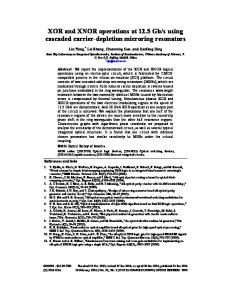
Various computational cameras have been developed to obtain additional information which cannot be acquired in the conventional camera [11, 12]. Additional information is used to solve fundamental problems of a conventional camera system such as depth estimation, motion deblurring, refocusing, and high dynamic range [13, 14]. Recently, computational cameras using multiple off-axis apertures were proposed for a new type of computational camera [15–19]. An aperture of an optical system is the opening that can adjust the amount of incoming light. The center of an aperture in a normal camera is aligned to the optical axis of the lens, and the convergence pattern on the image plane forms either a point or a circular region whose radius is determined according to the distance of the object from the focus plane as shown in Fig. 1(a). On the other hand, if the center of the aperture is not aligned to the optical axis, the convergence location of the incoming light is deviated from the optical axis as shown in Figs. 1(b) and 1(c). The MCA system is the extension of this approach using three apertures with different color filters. The main advantage of the MCA camera is that it provides both color and depth information that can be estimated from the direction and amount of color deviation from the optical axis. Maik et al. have originally proposed color shift model-based auto-focusing using the multiple color-filtered apertures system [17], and the rigorous analysis of the MCA system was given in [15]. Lee et al. have proposed a distance estimation method using dual off-axis color filtered apertures [19]. However the original contribution of this work is twofold: i) the proposed three different color-filtered apertures can provide better color reproduction, and ii) it
#239656 (C) 2015 OSA
Received 24 Apr 2015; revised 30 Jun 2015; accepted 14 Jul 2015; published 13 Aug 2015 24 Aug 2015 | Vol. 23, No. 17 | DOI:10.1364/OE.23.021958 | OPTICS EXPRESS 21960
(a)
(b)
(c)
Fig. 1. Comparison of the convergence patterns with different aperture positions.
can estimate color shifting vectors more robustly using three pairs of apertures. In the following section, we derive the relationships between color shifting vectors and circle of confusions. 3.
Object distance estimation by multiple off-axis aperture
The color deviation of the image acquired by a color shift model-based computational camera is characterized by a function of the distance of an object from the plane of focus. To analyze the color deviation, we consider a single-aperture model that has an off-axis aperture away from the optical axis as shown in Fig. 2.
Fig. 2. A thin lens model with a single off-axis aperture.
In the thin lens model, the focal length f has the relationship as 1 1 1 = + , where j ∈ { f ar, in, near}, f sj vj
#239656 (C) 2015 OSA
(1)
Received 24 Apr 2015; revised 30 Jun 2015; accepted 14 Jul 2015; published 13 Aug 2015 24 Aug 2015 | Vol. 23, No. 17 | DOI:10.1364/OE.23.021958 | OPTICS EXPRESS 21961
where s j represents the distance between the object plane and the lens, and v j the distance between the image plane and the lens. Given an object in an arbitrary position, the corresponding distances s and v are related with the in-focus distances sin and vin as 1 1 1 1 + = + , sin vin s v
(2)
and sin vin v . (3) vin v + sin v − sin vin To compute v, we analyze the relationship between the object distance and the corresponding shifting vector as shown in Fig. 3. If a circle of confusion is sufficiently small and the length of the shifting vector is determined according to the distance of the image plane from the lens, it can be computed using the property of similar triangles as s=
v=
vin dc , (dc − ∆)
(4)
where dc denotes the distance between the optical axis and the center of the aperture,and ∆ the shifting vector that represents the distance between the optical axis and the image of the object in the image plane. The object distance s in Eq. (3) can be expressed as sin vin dc . (5) vin dc + sin ∆ As a result, the object distance s is inversely proportional to the shifting vector ∆. If an optical system has multiple apertures, the imaging sensor also has the same number of multiple images and shifting vectors as shown in Fig. 1(c). We can separate the multiple images and shifting vectors in the image plane by using a different color filter in each aperture. As shown in Fig. 4, the incoming lights passing red and blue color-filtered apertures are focused in the corresponding color sensors, respectively, and the position of each image is determined by the single-aperture model. In the multiple off-axis aperture model, the direction of shifting vector is determined by the in-focused object distance sin . Therefore, we can estimate s by analyzing the direction and magnitudes of the shifting vector according to Eq. (5). s=
Fig. 3. The relationship between the object distance and the corresponding shifting vector the single-aperture model.
#239656 (C) 2015 OSA
Received 24 Apr 2015; revised 30 Jun 2015; accepted 14 Jul 2015; published 13 Aug 2015 24 Aug 2015 | Vol. 23, No. 17 | DOI:10.1364/OE.23.021958 | OPTICS EXPRESS 21962
(b)
(a)
(c)
Fig. 4. Different convergence patterns with multiple apertures and sensor.
4.
Depth-based defocus map estimation based on color shifting vectors
We estimate the object distance using color shifting vectors of off-axis apertures under the assumption that each circle of confusion is sufficiently small. In this section, a rigorous analysis of the circle of confusion is presented according to color shifting vectors. The size of a circle of confusion is determined by the distance of an object away from the plane of focus. If the object is placed on the in-focused plane, the circle of confusion ideally converges to a point, whereas it grows bigger if the object moves away from the in-focused plane as shown in Fig. 5.
Fig. 5. The size of a circle of confusion varies according to the object location.
Using the property of similar triangles, the diameter of a circle of confusion is computed as cnear =
dl (vnear − vin ) , vnear
(6)
c f ar =
dl (vin − v f ar ) , v f ar
(7)
and
where cnear and c f ar respectively represent diameters of circle of confusions when the corresponding objects are located at near- and far-focused planes, and dl the diameter of the aperture. #239656 (C) 2015 OSA
Received 24 Apr 2015; revised 30 Jun 2015; accepted 14 Jul 2015; published 13 Aug 2015 24 Aug 2015 | Vol. 23, No. 17 | DOI:10.1364/OE.23.021958 | OPTICS EXPRESS 21963
Since the diameter of a circle of confusion has a positive value, Eq. (6) and Eq. (7) can be generalized as dl (|v − vin |) . v Replacing the denominator in Eq. (8) with Eq. (4) yields, c=
c=
(8)
dl (|∆|) . dc
(9)
If sizes of the image and sensor are m × n and p × q, respectively, the shifting vector ∆ is computed as q p δ = δ, (10) m n where δ represents the shifted pixels in the image. p/m and q/n are the distance per pixel. The relation between the circle of confusion c and the object distance s can be expressed using Eq. (5) and Eq. (9) as ∆=
c=
dl vin (sin − s) . ssin
(11)
If centers of three apertures are located at the vertices of an equilateral triangle, the shifting vector can be expressed as 1√ 3a, 3 where a represents the distance among R, G, and B channels as shown in Fig. 6. δ=
(a)
(12)
(b)
Fig. 6. The relationship between the color shifting vectors and the distances among RGB channels in image and sensor.
Equation (12) states that both the object distance and depth-based defocus map can be estimated from the color shifting vectors. Although the ideal color shifting vectors have the same magnitude, we use the median value of three color shifting vectors that were estimated in RGB color channels.. The proposed defocus map estimation algorithm is summarized in Algorithm 1.
#239656 (C) 2015 OSA
Received 24 Apr 2015; revised 30 Jun 2015; accepted 14 Jul 2015; published 13 Aug 2015 24 Aug 2015 | Vol. 23, No. 17 | DOI:10.1364/OE.23.021958 | OPTICS EXPRESS 21964
Algorithm 1 Depth-based Defocus Map Estimation Input: Given Im , the acquired image by multiple color filtered apertures, the distance between the optical axis and the center of the aperture dc , the diameter of the aperture dl , the in-focus distances sin (or vin ), and the focal length f . Output: The defocus map is estimated using the circle of confusion c in the following steps. 1: Compute vin = sin f /(sin − f ), or sin = vin f /(vin − f ) 2: Compute the shifted pixel δ using Eq. (12) and a = median(agr , agb , arb ) as shown in Fig. 6. 3: 4: 5:
5.
Compute the shifting vector ∆ using Eq. (10) Compute the object distance s using Eq. (5) Compute the circle of confusion c using Eq. (11)
Experimental results
In this section, experimental results of the proposed defocus map estimation method using multiple off-axis apertures are presented. Hardware specifications used in the experiment are shown in Table 1. Table 1. Hardware Specifications of the Off-axis Aperture Camera
Camera type Image Sensor Image Lens Aperture Filter
Digital single lens reflex (DSLR) CMOS Sensor (36×24mm) Color image (R, G, and B channels, 5616×3744) Focal Length: 151mm Three Aperture (dc : 9.5mm, dl : 6.4mm) Gelatin Filter (R, G, and B colors)
In order to measure the relationship among the object distance, shifting vector, and circle of confusion, we acquired multiple images with different distances as shown in Fig. 7, and then color shifting vectors are estimated using the phase correlation method in [20].
#239656 (C) 2015 OSA
Received 24 Apr 2015; revised 30 Jun 2015; accepted 14 Jul 2015; published 13 Aug 2015 24 Aug 2015 | Vol. 23, No. 17 | DOI:10.1364/OE.23.021958 | OPTICS EXPRESS 21965
(a)
(b)
(c)
(d)
(e) Fig. 7. Experimental setup: (a) far-focused image, (b) in-focused image, (c) near-focused image, and (d) and (e) multiple, different object locations with the multiple color-filtered aperture camera with different sin ’s
#239656 (C) 2015 OSA
Received 24 Apr 2015; revised 30 Jun 2015; accepted 14 Jul 2015; published 13 Aug 2015 24 Aug 2015 | Vol. 23, No. 17 | DOI:10.1364/OE.23.021958 | OPTICS EXPRESS 21966
(a)
(c)
(b)
(d)
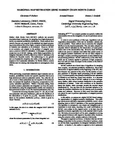
Fig. 8. Relationship between the object distance and the corresponding circle of confusion: (a,c) object distance according to shifting vector and (b,d) circle of confusions for the object distances in MCA.
Blue curves in Figs. 8(a) and 8(c) show the ground truth of object distances from the camera versus the magnitude of the shifting vectors, and red crosses show the estimated object distances according to Eq. (5). As shown in Figs. 8(a) and 8(c), the proposed method can accurately estimate the object distances. Blue curves in Figs. 8(b) and 8(d) show the ground truth of circle of confusion sizes according to the object distance, and red crosses show the estimated size of circles of confusion according to Eq. (11). As shown in the figure, the proposed method can accurately compute the size of circles of confusion corresponding to the object distance.
#239656 (C) 2015 OSA
Received 24 Apr 2015; revised 30 Jun 2015; accepted 14 Jul 2015; published 13 Aug 2015 24 Aug 2015 | Vol. 23, No. 17 | DOI:10.1364/OE.23.021958 | OPTICS EXPRESS 21967
(a)
(b)
(c)
(d)
Fig. 9. Comparison of different defocus map estimation methods: (a) the input image acquired by MCA, (b) the estimated defocus map by the Zhuo’s method [7], (c) the estimated defocus map by the Shen’s method [8], and (d) the estimated defocus map by the proposed method.
Experimental results of the proposed defocus map estimation algorithm are shown in Fig. 9 and Fig. 10. Figure 9(a) and Figs. 10(a)-10(b) show input images containing spatially varying blur according to the distances. Zhuo’s and Shen’s methods can estimate the amount of defocus blur only in the neighborhood of edges since they use intensity-based estimation as shown in Figs. 9(b)-9(c) and Figs. 10(c)-10(f). On the other hand, the proposed method successfully estimates the spatially varying blur that varies according to the object distances as shown in Fig. 9(d) and Figs.10(g)-10(h).
#239656 (C) 2015 OSA
Received 24 Apr 2015; revised 30 Jun 2015; accepted 14 Jul 2015; published 13 Aug 2015 24 Aug 2015 | Vol. 23, No. 17 | DOI:10.1364/OE.23.021958 | OPTICS EXPRESS 21968
(a)
(b)
(c)
(d)
(e)
(f)
(g)
(h)
Fig. 10. Comparison of different defocus map estimation methods: (a)-(b) two input images acquired by the MCA camera, (c)-(d) the estimated defocus maps using Zhuo’s method [7], (e)-(f) the estimated defocus maps using Shen’s method [8], and (g)-(h) the estimated defocus maps using the proposed method.
Figure 11 shows the result of spatially adaptive image restoration using defocus maps of Zhuo’s, Shen’s, and the proposed method. Since the proposed method estimates the defocus map using the correct distance information, it can successfully remove spatially varying out-offocus blur.
#239656 (C) 2015 OSA
Received 24 Apr 2015; revised 30 Jun 2015; accepted 14 Jul 2015; published 13 Aug 2015 24 Aug 2015 | Vol. 23, No. 17 | DOI:10.1364/OE.23.021958 | OPTICS EXPRESS 21969
(a)
(b)
(c)
(d)
(e)
(f)
(g)
(h)
Fig. 11. Comparison of the restored results using the estimated defocus map; (a) an input image acquired by the MCA camera, (b) the experimental setup, (c) the defocus map estimated by Zhuo’s method [7], (d) the restored image using (c), (e) the defocus map estimated by Shen’s method [8], (f) the restored image using (e), (g) the defocus map estimated by the proposed method, and (h) the restored image using (g). #239656 (C) 2015 OSA
Received 24 Apr 2015; revised 30 Jun 2015; accepted 14 Jul 2015; published 13 Aug 2015 24 Aug 2015 | Vol. 23, No. 17 | DOI:10.1364/OE.23.021958 | OPTICS EXPRESS 21970
Table 2 summarizes quantitative analysis of Zhuo’s, Shen’s, and the proposed methods. To analyze the accuracy, the defocused image was restored using defocus maps estimated by the three methods. We used L1-2 optimization [8] and Wiener filter [21] as image restoration methods. For the quality assessment, we used natural image quality evaluator (NIQE) [22] and spectral and spatial sharpness(S3 ) [23]. It is to note that the proposed method produces the best result in most NIQE and S3 values. Table 2. Comparison of the restoration performance using various defocus map.
Input
Image 1
Image 2
Image 3
Image 4
6.
Method Zhuo’s method [7] Shen’s method [8] Proposed method Zhuo’s method [7] Shen’s method [8] Proposed method Zhuo’s method [7] Shen’s method [8] Proposed method Zhuo’s method [7] Shen’s method [8] Proposed method
NIQE L1-2 Wiener filter optimization 5.1481 8.9015 4.5473 6.9794 3.6184 3.8842 4.4525 8.9015 4.4645 6.9794 3.6184 3.8842 5.1612 5.5437 5.9406 7.9970 5.2891 4.9775 5.4112 5.3479 5.8880 5.7121 5.3032 4.7969
S3 L1-2 optimization 0.4596 0.4532 0.4920 0.4596 0.4532 0.4920 0.3233 0.2812 0.3361 0.2515 0.2197 0.2633
Wiener filter 0.9879 0.9399 0.9491 0.9879 0.8960 0.9789 0.8404 0.8546 0.9153 0.7622 0.5432 0.7882
Conclusion
In order to estimate the defocus map using a color shift model-based computational camera, a combined optical and mathematical model of off-axis apertures is presented. Based on the assumption that an image has multiple objects at different distances from the camera, each object region is out-of-focused by the corresponding circle of confusion that is determined from the object distance. Misaligned regions among color channels are registered for computing color shifting vectors, and the object distance and the corresponding circle of confusion are estimated from the color shifting vectors. Since the propose method uses the real object distance, it can correctly estimate the spatially varying blur without manually tuning parameters in a single input image. Although the proposed approach primarily focuses on the estimation of the defocus map using the image acquired by the color shift model-based computational camera, it can also be used for any types of color misaligned and/or spatially varying out-of-focused images. To acquire the highly accurate defocus map, an improved registration method will be developed in the future. Acknowledgments This work was supported by Institute for Information & communications Technology Promotion(IITP) grant funded by the Korea government(MSIP) (B0101-15-0525, Development of global multi-target tracking and event prediction techniques based on real-time large-scale video analysis) and the Technology Innovation Program (Development of Smart Video/Audio Surveillance SoC & Core Component for Onsite Decision Security System) under Grant 10047788.
#239656 (C) 2015 OSA
Received 24 Apr 2015; revised 30 Jun 2015; accepted 14 Jul 2015; published 13 Aug 2015 24 Aug 2015 | Vol. 23, No. 17 | DOI:10.1364/OE.23.021958 | OPTICS EXPRESS 21971