FUTA Journal of Research in Sciences, Vol. 12 (2) 2016: 325 - 333
DEPTH ESTIMATION OF MINERAL DEPOSIT USING MAGNETIC METHOD IN ODUDUWA UNIVERSITY, IPETUMODU, SOUTHWESTERN NIGERIA *1
S.O. Sedara,; 2O.O. Alabi, and 3D.D. Akinwande, Department of Physics and Electronics, Adekunle Ajasin University, Akungba-Akoko, Ondo State 2 Department of Mathematical and Physical Sciences, Osun State University, Osogbo, Osun State 3Department of Integrated Science, Adeyemi College of Education, Ondo, Ondo State, Nigeria *
[email protected] *1
ABSTRACT
In this study we delineate the subsurface structures in an open field in Oduduwa University, Ipetumodu, Osun State covering 500m2 using magnetic methods. The goal is to estimate depth to top and centre of mineral deposit of the study area. Ground magnetic survey was carried out along ten (10) profiles. The data set was processed and interpreted using a series of techniques and software (the slope methods, trend analysis and Golden software). The results indicate that profile 1 has the highest amplitude of 12.4 nT followed by profile 5 with 10.2 nT. The depth to basement top estimate ranges from 2.25 to 6.65 m while depth to center ranges from 8 to 25m. The magnetic anomaly obtained is between -8.8 nT and +5.8 nT. The ground magnetic contour, 3-D and vector maps showed that magnetic anomalies are as a result of rocks present in the region. The major rocks and minerals suspected to be found in this area and its environment are slate, gneiss and serpentenite. The high intensity values strongly suggest the presence of ferromagnetic minerals. The suspected points to have a high presence of minerals in the study area are between profiles 1 and 5. Keywords: Magnetic field, Magnetic anomaly, Basement, Oduduwa University INTRODUCTION The increasing importance given to environmental challenges has recently prompted the scientific society to improve on the geophysical techniques intended at the discovery of mineral ore deposit. The discovery and location of these mineral ores can be detected through several geophysical techniques (Foley, 1994; Gibson et al.,1996; Marchetti, et al., 1998). Efforts have been made by geological and mining engineers to find the meaning of the structure of the outermost formations of the Earth’s crust. These have led to diverse comprehensive studies, which now stand as building-block to their efforts. Based on the aim and
objectives of investigation, there are many geophysical methods suitable to different situations. These methods include; magnetic, gravity, electrical, electromagnetic methods, to mention but few (Keary and Brooks, 2002; Musset and Khan, 2000) and this research makes use of these magnetic methods. The magnetic method of geophysical prospecting is a geophysical technique that measures variations in the earth’s magnetic field to determine the location of subsurface features. This non destructive technique has numerous applications in engineering and environmental studies. These include; the location of voids, near-surface faults, igneous dikes, and buried ferromagnetic
325
S.O. Sedera et al., FUTA J. of Res. in Sci., Vol. 12 (2) 2016: 325 - 333
objects like storage drums, pipes etc (Butler, 2005; Lowrie, 2001). In general, the technique that is aforementioned makes use of the magnetic survey which is constantly used for a quick detection of underground metallic refuse. This technique involves two different kinds of measurements viz the total intensity of the local magnetic field and its vertical gradient. The discovery of metallic hidden objects using magnetometric survey accounts for the low cost of its non-persistent implementation, the quickness of data acquisition and processing. The analysis and localization of these hidden objects with only magnetic signature, depends solely on the depth of the object used and its makeup; since a nonmagnetic body is completely unable to detectable. This limitation can be dormant if other geophysical techniques (electromagnetic, GPR and electrical resistivity) which focused on different physical properties of the affected matter are used. An application of ground magnetic surveys to the structural interpretation of an area is described in this study. Oduduwa University site (study area) is located within a tropical climate differentiated by irregular wet and dry seasons. The relationship existing between tectonic structures and mineralization makes this area an excellent prospecting target. This research work focuses on the data collected from the interpretations of the ground magnetic survey on a subsurface geological structure.
The primacy given to magnetic survey is such that deep insight into the depth of the top and center of magnetic sources in the area is delineated. Location and Geology of the Study Area The study area is situated at the Ipetumodu area of Osun State, Nigeria. It lies between latitudes 7.504268 and 7.504434°N and longitudes 4.452252 and 4.452925°E. The geology of this area is of Precambrian rocks that are characteristic for the basement Complex of Nigeria. The major rock found within the area form part of the Proterozoic schist belts of Nigeria (Figure 1). In terms of structural features, lithology and mineralization, the schist belts of Nigeria show considerable similarities to the Achaean Green Stone Belts. Previous study has shown that the south western region of Nigeria is characterized by solid mineral deposit and more research work should be carried out to discover these minerals (Joshua et al., 2010). Also some studies have shown that this area is characterized by Precambrian rocks typical of the basement Complex of Nigeria (Adekoya et al., 2003; Ajayi and Ogedengbe, 2003; Obaje, 2009). The topography of the area is gentle with few local outcrops in the northeastern and northwestern part. There have been contradictory reports on the nature and lateral shift of the major faults in this area hence the necessity for this work.
Theory of Magnetic Methods The source of the earth’s magnetism is assumed to be the liquid outer core. This cools outside and it leads to the material becoming denser and sinking towards the inside of the outer core and new warm liquid matter rising to the outside (Telford Figure 1. Location and Geological Map of study Area 326
S.O. Sedera et al., FUTA J. of Res. in Sci., Vol. 12 (2) 2016: 325 - 333
et al., 2001). Thus, liquid metallic matter generates convection currents which move through a weak cosmic magnetic field that subsequently produce induction currents. It is this induction current that generate the earth’s magnetic field (Telford et al., 2001; Lowrie, 2001). Crystals with magnetic minerals are the major content of most rocks of the earth’s crust. Thus, most rocks contain some certain amount of magnetism which usually have two components; induction by the magnetic field present while taking measurement and remnant formed during geologic history (Reijers, 1996). Ground magnetic study however is used for detail mapping in order to understand the subsurface geology of an area. The technique requires measurements of the amplitude of magnetic components at discrete points along traverses distributed regularly throughout the survey area of interest. In ground magnetic study, three components are examined. These are horizontal, vertical and total components. The vertical components and the total components were mostly used in the past studies to delineate faults, fractures, depth to magnetic basement and other geological structures (Folami, 1992; Kayode, 2006, Akintayo, 2013). (1) Equation (1) above is the required potential equation within the regions occupied by magnetic bodies.
MATERIALS AND METHODS Data Acquisition and Processing Magnetic measurements were carried out using a proton magnetometer that involves three components. These components are; vertical, horizontal and total magnetic intensities. Ten (10) traverses of 150 points along East-west and West-east profiles were developed. The station interval was 10 m while the distance between lines was 5 m. The total area of the survey location was 500 employed in determining the depth to the top through trend analysis. The maximum slope
m2. The data acquisition technique requires measurements of the magnetic intensities at discrete points together with traverses regularly distributed within the study area. The magnetic data developed were processed so as to prepare the dataset for interpretations. The procedures for data processing include; drift correction, and plotting of the relative magnetic profiles. The peak points (positive or negative) on the magnetic profile plots are taken as reference points for the results of the depth estimation. For accuracy during measurement, the best method is to adjust the sensor in the same direction at each station wherever the measurement is being carried out. Figure 2 shows the grid points (profiles layout) in the study area. While preparing the data for interpretation, it was arranged traverse by traverse, and the line of best-fit was drawn in each profile to obtain the residual value of magnetic intensity, using Microsoft Excel. The value on the line was taken from the original (raw data) value to obtain either positive or negative values, which depicts anomaly in the data. On each profile, a tangent was drawn to the point of maximum slope, using a right-angled triangle construction and also a second line with half the same slope was drawn. The horizontal distance (S) between these two tangents is a measure of the depth to the magnetic body. The method of obtaining the above horizontal distance (S) is the half slope method. The estimate depth (d) to the top of the magnetized body can be calculated using equation 2, where (S) is the horizontal distance between half-slope tangents and (k) is constant (1.2 ≤ k ≤ 2; usually k=1.6). The vector map (Figure 13) and contour map (Figure 14) were constructed using the Surfer software. d = kS
(2)
The half-slope technique calculates the depth estimation of buried magnetic body to the top of the basement rocks. After data correction, the following steps were of the anomaly for each profile was determined using a right-angled triangle
327
S.O. Sedera et al., FUTA J. of Res. in Sci., Vol. 12 (2) 2016: 325 - 333
construction. Two lines constructed with a slope, which was equal to half the maximum slope and tangential to the curve, were measured. The horizontal separation between the two points of tangent is an approximate evaluation of the depth to the magnetic body. The slope of the curve created by the anomaly in a profile data determines the estimation of the depth of magnetic anomaly. The depth of an anomaly is related to the horizontal extent of tangent to the maximum slope. Another basic concept of estimating the slope method is to approximate the anomaly curve using a straight line, whose slope is the
maximum slope of the anomaly. The approach is to determine two points; points at which lines with half the maximum slope are tangent to the magnetic profile, and divide the horizontal distance by an “index value” of 1.2 to 2.0. This index value increases with the width to the depth ratios for the causative body. It is assumed in general, that the depth of investigation is a function of the target size and shape for near surface investigations, and this depth of investigation varies from 0 to 55 m depending on the quantity (i.e. size) of the hidden source (Philip et al., 2002; Butler, 2005).
Figure 2. Schematic Layout of profiles of Study area
328
S.O. Sedera et al., FUTA J. of Res. in Sci., Vol. 12 (2) 2016: 325 - 333
serpentenite, rhyolite, pegmatite, gabbro, basalts, oceanic basalts and hematite.
RESULTS The vector map (Figure 13) suggests appreciable magnetic minerals that cause special changes in the direction of magnetic field. It clearly highlights different changes in the direction of the magnetic field, which suggests that the target location where the magnetic mineral is more significant appears within that region of the map, and such area indicates the likely presence of minerals such as slate, gneiss mentioned earlier. The contour lines displayed in Figure 14 characterizes sharp gradient which are areas with higher magnetic susceptibility. Contour lines that are widely spaced imply shallow slope, which is an area with lower magnetic susceptibility. The prominence of sudden change in the contour over an appreciable distance, with frequent trend in the south-west direction of the study area, implies discontinuity in depth, possibly due to subsurface major faults. The 3D plot (Figure 15) has shown the location and signatures of the magnetic minerals in the study area. The area of the map is also good for engineering purpose and other part of the map, where the directions point towards the east, shows low magnetic signature and that area is good for hydro-geologic purpose. Six out of the ten magnetic plots clearly have distinct magnetic signatures. Tables 1 and 2 presents and determines the estimated basement depths to top and center of anomaly.
This was achieved using susceptibility data by (Reynolds, 1997). High residual points (maximum and minimum peaks on magnetic plots) observed (Figures 3-12) are suspected areas with near surface rocks with appreciable magnetite content. The peak points on profile 3 (Figure 5) are suspected to be fractured because of the wide gap between the two peak points. Low residual points on Figures 8 and 9 are suspected area with non-magnetic minerals or contact between rocks which are good points for hydro-geologic purposes.
Figure 3. Corrected Magnetic Field Plot for Profile 1
DISCUSSION
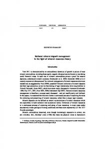
Profile 1 has the highest amplitude of 12.4 nT followed by profile 4 and profile 8 with amplitude 3.5 and 3.4 nT, respectively. It was also observed that the minimum depth is 2.25 m which indicates near-surface feature and maximum depth of 6.65m. The major rocks and minerals suspected to be found in this studied area and its environs are slate, gneiss,
Figure 4. Corrected Magnetic Field Plot for Profile 2
329
S.O. Sedera et al., FUTA J. of Res. in Sci., Vol. 12 (2) 2016: 325 - 333
Figure 5. Corrected Magnetic Field Plot for Profile 3
Figure 6. Corrected Magnetic Field Plot for Profile 4
Figure 8. Corrected Magnetic Field Plot for Profile 6
Figure 9. Corrected Magnetic Field Plot for Profile 7
Figure 10. Corrected Magnetic Field Plot for Profile 8 Figure 7. Corrected Magnetic Field Plot for Profile 5
330
S.O. Sedera et al., FUTA J. of Res. in Sci., Vol. 12 (2) 2016: 325 - 333
Figure 11. Corrected Magnetic Field Plot for Profile 9
nT Figure 14. Contour Map of Study area
nT Figure 15. 3D Surface Map of study area Figure 12. Corrected Magnetic Field Plot for Profile 10
Table 1. Showing depth to centre of anomaly body or source
Profile 1 Profile 2 Profile 3 Profile 4 Profile 5
Point 1 8m 11m 12m 18m 12m
Point 2 16m 6.5m 12m 20m 16m
Point 3 15m 6.5m 15m 12m
Point 4 10m 12m 12m
Point 5 -
Profile 6 Profile 7 Profile 8 Profile 9 Profile 10
10m 10m 10m 8m 6m
22m 10m 16m 10m 12.5m
8m 16m 6.5m
-
-
Figure 13. Changes in Magnetic field direction of Study area 331
-
S.O. Sedera et al., FUTA J. of Res. in Sci., Vol. 12 (2) 2016: 325 - 333
Table 2. Showing depth to top of anomaly body or source
Profile 1 Profile 2 Profile 3 Profile 4 Profile 5 Profile 6 Profile 7 Profile 8 Profile 9
Point 1 5m 2.875m 6.5m 4.375m 2.25m 3.75m 2.5m 5.625m 2.875m
Point 2 2.25m 2.5m 2.5m 3.75m 2.5m 2.5m 1.75m 3.5m 3.125m
Point 3 3.125m 2.5m 3.125m 2.5m 2.5m -
Point 4 2.5m 2.5m 2.25m -
Profile 10
2.25m
2.25m
2.15m
-
CONCLUSION The ground magnetic study of the area has helped to delineate the geophysical characteristics of the area. The profiles (Figures 3-15) obtained from the data have helped to determine approximate depth to the magnetic basement of the studied area. Also it has helped in producing contour map, 3D Surface map for the study area which will serve as a reference for further studies in the region. Profile 1 has the highest amplitude of 12.4 nT and profile 5 having 10.2 nT. The depth to the top of basement rocks ranges between 2.25 to 6.65 m. The highly mineralized region of the study area is between profiles 1 to 5. Hence, there is a need for further study using more advanced approach so that ground magnetic study can equally expose lithological units in basement structures to meet the demands of searching for mineral deposits in the area. REFERENCES Adekoya, J. A., Kehinde-Phillips, O. O. and Odukoya, A. M. (2003). Geological distribution of mineral resources in Southwestern Nigeria,” in Prospects for Investment in Mineral Resources of Southwestern Nigeria, Elueze, A. A. Ed., pp. 1–13, Nigerian Mining and Geosciences (NMGS), 2003.
Ajayi, T. R. and Ogedengbe, O. (2003) Opportunities for the exploitation of precious and rare metals in Nigeria,” in Prospects for Investment in Mineral Resources of Southwestern Nigeria, Elueze, A. A. Ed., pp. 15–56, Nigerian Mining and Geosciences Society (NMGS), 2003 Akintayo, O.O. (2013). Geomagnetic and geoelectric investigation of mineral rocks at Awo, Osun State, southwest Nigeria,” International Journal of Physical Research, vol. 1, no. 2, pp. 60–74, 2013 Butler, D. K. (2005). Near Surface Geophysics Textbook, vol. 13, Society of Exploration Geophysicist. Folami, S.L. (1992). Interpretation of Aeromagnetic Anomalies in Iwaraja area, Southwestern Nigeria. Journal of Mining and Geology 28(2):391-396. Foley, J.E. (1994). Stolmstm Magnetic survey at Sandia National Laboratory Technical area 2, in Proceedings of the Symposium on the Application of Geophysics to Engineering and Environmental Problems, March 27-31, 1994 Boston, Mass., edited by R.S. Bell and C.M. Lepper 895-907 Gibson, P.J., Lyle, P. and Gorge, D.M. (1996). Environmental applications of magnetometry profiling, Environmental Geology 27:178-183 Joshua, E.O., Popoola, O.I., Sedara, S.O., and Ayoade, O.A. (2010). Ground Magnetic Survey for the Investigation of Mineral Ore Deposit at Itesi village in Orile Ilugun, Ogun State, Nigeria. Nigerian Journal of Science. 44:11-16 Kayode, J.S. (2006). Ground Magnetic Study of Jeda-Iloko Area, Southwestern Nigeria and Its Geologic Implications. M.Tech. Thesis Federal University of Technology, Akure, Nigeria. Keary, P. and Brooks, M. (2002). An Introduction to Geophysical Exploration: Blackwell Science Ltd, Oxford 3rd ed., p. 255
332
S.O. Sedera et al., FUTA J. of Res. in Sci., Vol. 12 (2) 2016: 325 - 333
Lowrie, W. (2001). Fundamentals of Geophysics, Cambridge University Press, Cambridge, UK, 2nd edition, 2011. Marchetti, M., Chiappini, M. and Meloni, A. (1998). A test site for magnetic detection of buried steel drums, Annals of Geophysics 41(3):491-498 Musset, A.E. and Khan, M.A. (2000) Looking into the Earth: An Introduction to Geological Geophysics, Cambridge University Press. Obaje, N. G. (2009). Geology and Mineral Resources of Nigeria, vol. 120 of Lecture Notes in Earth Sciences, Springer, New York, NY, USA, 2009. Philip, K., Brooks, M. and Hill, L. (2002). An Introduction to Geophysical Exploration, Blackwell Science, London, UK, 3rd edition, 2002.
Reijers, T.J.A. (1996). Selected Chapters in geology. Shell Petrol. Dev. Company, Warri, Nigeria, 87-90. Reynolds, J.M. (1997). An Introduction to Applied and Environmental Geophysics.Reynolds Geo-Sciences Ltd, UK, Telford, W.M., Geldart, L.P. and Sheriff, R.E. (2001). Applied Geophysics, 3rd Edition, Cambridge University Press, Cambridge. 632-638
333