Description B. CCD array camera OptoLine OL 80.. BEA--220265-EN-04 en. 1.
General instructions. 2. 2. Type references. 2. 3. Function. 3. 4. Camera controls.
Description B
CCD array camera OptoLine OL 80.. 1. General instructions 2. Type references 3. Function 4. Camera controls 5. Assembly 5.1 Determining scanning direction 5.2 Determining camera measuring range and distance between camera and web 5.3 Determining the light transmitter size and distance M between the light transmitter and camera 5.4 Camera assembly 5.5 Light transmitter assembly 5.6 Determining the background 5.7 Mount support roller 6. Installation 7. Commissioning 7.1 Position camera 7.2 Check wiring Check wiring 7.3 Check supply voltage 7.4 Set camera CAN address 7.5 Position the web edge in the camera visual range 7.6 Set the camera aperture and focusing 7.7 Camera configuration 7.8 Camera calibration 7.9 Width measuring function calibration 7.10 Perform application-dependent settings 8. Operation 8.1 Specify set position value for guiders 9. Camera start-up response 10. Paramter list (Excerpt) 11. Error messages 12. Maintenance 13. Technical data
en
2 2 3 6 7 7 7 8 9 9 10 10 11 11 12 12 12 12 13 13 16 20 23 23 26 26 27 28 30 31 31
BEA--220265-EN-04
CCD array camera OptoLine OL 80..
1. General instructions 1.1 Description
This description applies for all CCD array cameras in the OL 80.. series. It explains the standard operation for width measuring and web guiding with one or two cameras on a moving web. Keep the description in a safe place, accessible to personnel at all times. The description is part of the package supplied and should be read carefully prior to assembly, operation and maintenance work.
1.2 Explanation of symbols
➜ jobs to be performed important information and instructions
1.3 Operation
The CCD array camera Opto Line OL 80.. should only be operated by qualified personnel or suitably instructed persons.
2. Type references
CCD array cameras in the OL 80.. series are only differentiated by their various lenses (measuring ranges). The function of the cameras is identical. The first two digits of the type reference indicate the camera resolution (80 = 8192), the third and fourth digits, the lens focal length. Example: OL 8028
B Page 2
BEA--220265-EN-04
focal length 28 mm
CCD array camera OptoLine OL 80..
3. Function
3.1 Purpose
The CCD array camera Opto Line OL 80.. was developed for contact-free position measuring. It detects the position of contrasts (edges, lines, flutes or grooves) on a moving web. The measuring result can be used for width measuring, web guiding, following up actuators or tools such as cutters etc. . In this description the camera and standard operation for width measuring and web guiding with one or two cameras is explained. Specialised applications designed by E+L are described separately in the system specifications or operating instructions.
3.2 Design
A width measuring system consists of: - one or several cameras - a set of cables - one or two light transmitters - a DO 002. remote display A web guiding system consists of: - one or several cameras - a set of cables - one or two light transmitters - an E+L controller with command station
3.3 Operating principle Frontlighting
Scanning methodes
Backlighting
Two different scanning methods are used to detect contrasts, frontlighting and backlighting. The method applied depends on the individual job. With the frontlighting method the light transmitter and camera are on the same side, either above or below the object. The camera catches the light reflected by the object from the light transmitter. When frontlighting is used, outer edges and lines, flutes or grooves can all be detected.
BEA--220265-EN-04
B Page 3
CCD array camera OptoLine OL 80.. With the backlighting method the light transmitter is positioned behind the object to be scanned, as seen from the scanned object. In the case of non-transparent materials, only the outer edges are detected. The following applies for both methods: Whether one or two cameras are used to establish the position depends on the resolution and web width required (see block diagram). What is important is that when width measuring or web guiding with one camera, both web edges are always in the camera visual range. When width measuring or web guiding with two cameras, one web edge each must be in the camera visual range. The centerpiece of the camera is a charge coupled device with 2048 pixels. The individual pixels convert the light shed into signal voltages. Contrast changes in the camera measuring range such as a web or printed line on a web cause a change in the voltage. The camera can detect up to 30 contrast changes in its measuring range, regardless of whether these are caused by one or several webs. See fig. on page 5. A maximum of 8 measuring values can be output on the basis of the positions recorded. A measuring value is a contrast position (e.g. the web edge position) or the center between two contrasts (e.g. the web or line center position). The built-in light controller makes the camera practically impervious to soiling caused by dust and environmental factors such as steam or ambient light fluctuations. All data to the camera (camera settings, measured value selection) and from the camera (measured value position, error messages, status information) are transferred via a CAN interface. The CAN controller is built into the camera. The in-house E+L protocol is used on the CAN bus. Coupling to other buses or unit interfaces is established via special interface modules that can be attached to the CAN bus. Two keys and a 16-bit LED display are available for basic operating functions, setting the CAN address, focusing the camera and displaying the measured value position. Further settings are performed via an E+L command station DO.. or RT.. .
*CCD = Charge-Coupled-Device B Page 4
BEA--220265-EN-04
CCD array camera OptoLine OL 80..
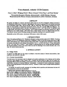
CCD-camera
Light transmitter
Edge
CCD camera visual range
Printed line (dark) Web (light) Background
Scan on oscilloscope 1
Pixel 1
1 Edge 2/3 Line
23
2048
Scanning direction
Frontlighting principle
BEA--220265-EN-04
B Page 5
CCD array camera OptoLine OL 80..
4. Camera controls
LED display In normal mode, the LED display indicates the position of the measured value (e.g. the web center) in the camera measuring range. In the event of malfunctions, it indicates various errors, see error messages section. Arrow The LED on the arrow indicates when the camera is ready for operation. When connected to the power, it lights up red until camera initialization is complete. When the camera is ready for operation it lights up green. GRP key Use the GRP key to set the group number and focus the camera, see the "Setting the camera CAN address" and "Focusing the camera" sections. DEV key Use the DEV key to set the camera device number, see "Setting the camera CAN address" section.
Camera controls
The DEV key is also used to set which measured value is to be indicated on the LED display. Press and hold down the DEV key. The address of the measured value currently being displayed is indicated. The addresses of all configured measured values are displayed in sequence at 5 second intervals. Release the key once the address of the required measured value appears. Other settings by the E+L Setup Editor.
B Page 6
BEA--220265-EN-04
The setup editor is a software tool for calibrating and configuring E+L CAN modules such as camera OL 80.. . In setup mode parameters can be displayed and some changed as well. Setup mode is accessed via a command station DO .... or operator panel RT .... . See description "CAN-Bus, serial bus and setup editor".
If the cameras are used only for width measuring, i.e. the system only has a remote display DO 002. (no E+L controller DC..), the device number of the remote display must always be 5 (device 5). Only then can the setup editor be started.
CCD array camera OptoLine OL 80..
5. Assembly
Please observe the locally applicable and professional safety and accident prevention regulations. Assembly procedure: 5.1 5.2 5.3 5.4 5.5 5.6 5.7
5.1 Determining scanning direction 5.2 Determining camera mea suring range and distance between camera and web
Determine scanning procedure Determine camera measuring range and distance between camera and web Determine the size of the light transmitter and the maximum distance between the light transmitter and camera Assemble camera Assemble light transmitter Determine background, mount black screen as required Mount support roller as required
Select frontlighting to scan lines or transparent webs, edges on opaque webs should be scanned using backlighting. In border cases, the suitable scanning process should be selected by trial and error. The distance K between the camera and web influences the camera measuring range: - the shorter the distance, the smaller the measuring range
K
Web
- the smaller the measuring range, the more precise the measurement (resolution) The following diagram will help you determine the distance between the camera and web for assembly purposes. The dimensions in the diagram are approximate.
Distance between camera and web Measuring range in cms OL 8024 OL 8028
OL 8050
Distance between camera and web K in cms
BEA--220265-EN-04
B Page 7
CCD array camera OptoLine OL 80.. * Depending on the application, a safety clearance of 50-100 mm must be allowed for in each case.
5.2.1 Systems with one camera: measuring range = max. web width + max. web movement ** + safety *
5.2.2 Systems with two cameras:
**On applications with an a ctuating element, e.g. pivoting frame, the stroke must be taken into account with regard to web movement.
measuring range = max. web width - min. web width + max. web movement ** + safety * 2
5.3 Determining the light transmitter size and distance M between the light transmitter and camera
The E+L light transmitter is available with one fluorescent tube (FS 16.1) and with two fluorescent tubes (FS 16.2). If sufficient space is available, the light transmitter should always be used with two fluorescent tubes.
The web must never lie outside the camera measuring range.
When selecting the light transmitter, please observe the following criteria: - distance K between the camera and web - distance L between the light transmitter and web - the light transmitter operational range CCD camera
CCD camera visual range Web Light transmitter Operational range ... not usable
100 mm ... Measuring range Distances: camera-Light transmitter-Web
Distance K between the camera and web is determined by the measuring range. Distance L between the light transmitter and web determines the scanning process. When using frontlighting the distance between the light transmitter and the web should be as short as possible to capture the maximum amount of light. The following applies for backlighting; the shorter the distance between the light transmitter and the web, the greater the danger of dirt being sharply depicted on the light transmitter, causing incorrect measurements. We recommend a minimum dis tance of 100 mm. The camera visual range must always be located in the light transmitter operational range. On E+L light transmitters, the outer 100 mm are not usable for the cameras.
B Page 8
BEA--220265-EN-04
CCD array camera OptoLine OL 80.. The following table lists the maximum distance of standard E+L transmitters to the camera. Light transmitter length FS 16.1
FS 16.2
Light transmitter h
Maximum mounting distance camera - light transmitter M
operational range
OL 8024
OL 8028
OL 8050
665 mm
685 mm
450 mm
400 mm
460 mm
830 mm
1275 mm
1295 mm
1050 mm
900 mm
1050 mm
1880 mm
1575 mm
1595 mm
1350 mm
1150 mm
1340 mm
2400 mm
The longer the light transmitter, the greater the gap will be. The maximum mounting distance can be calculated as follows: M = f (a+b) b
5.4 Camera assembly
M = Max. mounting dist. camera - light transmitter M in mms a = Light transmitter operational range in mms b = CCD element length = 28,67 mm f = Lens focal length (24, 28 or 50 mm)
If the camera looks down on the web from above, it should be mounted so that the arrow on the camera operating controls points in the direction of web travel. If the camera looks up to the web from below, the arrow should point in the opposite direction to that of web travel. On camera systems designed by E+L, the module reference must also be checked (e.g. B 2). The block diagram specifies exactly which camera should be mounted on which side of the web, seen from the direction of web travel. Two different E+L supports are available for mounting the camera, see attached drawing. We recommend you pin the supports once the camera has been positioned (7.1 commissioning).
5.5 Light transmitter assembly
How the light transmitter is mounted depends on the scanning process implemented. 1.
2.
Vertical web travel
3.
Horizontal web travel
Light transmitter assembly with backlighting principle
When using backlighting we recommend the three mounting variants above to avoid soiling.
BEA--220265-EN-04
B Page 9
CCD array camera OptoLine OL 80..
Web Light transmitter assembly with frontlighting principle
Background
Background
When using frontlighting the following should be observed: - when scanning the edges of transparent webs, mount the light transmitter so that the mirror surface reflects the light sent from the transmitter into the camera (see illustration above left). - when detecting lines and colour contrasts on transparent and opaque webs, mount the light transmitter so that a diffuse reflection is produced. Surface glare is avoided and a clear image is produced (see illustration above right). When frontlighting, please ensure that the light transmitter is not in the camera visual range. 5.6 Determining the background
A uniform contrast-free dark background is required for frontlighting. You may have to mount a matt black panel behind the web, in the camera visual range. This optimum contrast to the web guarantees efficient web edge scanning, influences from external light sources are avoided.
5.7 Mount support roller
It must be guaranteed that the web does not form folds or creases and that the edges do not turn up as otherwise the light is reflected at a different angle by the web and no longer captured by the camera. A support roller can be mounted if necessary. With front-lightning, the support roller should be mounted outside the camera measuring range, either before or after the camera. See illustration on left.
Background
Support roller Example: frontlighting Support roller mounted after the camera
B Page 10
BEA--220265-EN-04
CCD array camera OptoLine OL 80..
6. Installation
➜ Run electrical leads according to the attached wiring diagram and EMC instructions. ➜ Protect and run CAN bus lines away from noisy or heavy currentcarrying leads. Ensure that:
7. Commissioning
insulation is not damaged and the leads properly secured and protected.
the total length of the CAN bus line is limited to 200 m and may not exceed this.
a terminating resistor connector is attached to both ends of the CAN bus line. 3-pole plugs are used as CAN bus connectors.
when using your own light transmitters, that they feature an electronic ballast (min. 5 kHz).
Procedur 7.1 Position camera 7.2
Check wiring
7.3
Check supply voltage
7.4
Set/check camera CAN address
7.5
Position web edge in the camera visual range
7.6
Set camera aperture and focusing
A. aperture
B. focusing
7.7
Configure camera
7.8
Calibrate camera
7.9
Calibrate width measurement
7.10
Perform application-dependent settings
BEA--220265-EN-04
B Page 11
CCD array camera OptoLine OL 80.. 7.1 Position camera
Example: Backlighting
➜ Set the camera visual range (CCD array) at a 90° angle to the web surface and web center. Ensure when measuring with two cameras, that both are set at the same distance A from the web. ➜ For frontlighting, align the camera and light transmitter with one another (see illustration on top of page 10). 7.2 Check wiring Check wiring
➜ See wiring diagram.
7.3 Check supply voltage
➜ See wiring diagram.
7.4 Set camera CAN address
The camera has a CAN address by which it can be reached via the bus. The CAN address consists of a group and device number. The (Group) number refers to which control loop the device belongs, the (Device) number to the specific device in the control loop. On systems designed by E+L the CAN address is works set. The CAN address is specified on the type plate along with the module reference and is listed in the system block diagram. If cameras are supplied individually, as a component of systems not designed by E+L, you must set the CAN address. To do so, see the "CAN bus, serial bus and setup editor" description. In this case, cameras are supplied with CAN address 0.1. The camera device numbers are fixed, see table below. The device numbers specify the mounting location (to the right or left in the direction of web travel) and thus the camera edge scanning direction. Device number
B Page 12
BEA--220265-EN-04
Sensor in direction of web travel
1
- camera on right - only one camera over web center
2
- camera on left
3
- second camera on right (for special applications)
4
- second camera on left (for special applications)
CCD array camera OptoLine OL 80.. Group number
Device numbe
Enter CAN address: ➜ Press and hold down the GRP and DEV keys on the camera operating panel at the same time. After approx. 10 seconds, the set CAN address will flash on the LED display (see fig. opposite). After a further 20 secs, the camera will switch to the mode for setting the CAN address. The flashing becomes a permanent light. ➜ Let go the GRP and DEV keys. ➜ Set the group number with the GRP (0-7) key and the device number with the DEV (0-4) key.
Example CAN address 01: Camera on right or only one camera over the web center
Terminating address entry: Address entering is terminated after approx. 20 secs if no key has been pressed within this period. A reset is automatically performed once this time has elapsed and the new CAN address adopted.
7.5 Position the web edge in the camera visual range
➜ Position the web edge in the camera measuring range. The web must lie on the same level as it will subsequently run through the machine. Height fluctuations distort the measuring result.
7.6 Set the camera aperture and focusing
➜ Screw off the protective cylinder on the lens. The aperture on OL 80 cameras is focused like a normal camera by adjusting the front ring, the aperture on the right behind. See fig. opposite.
Aperture
If the lens is secured against twisting by an O-ring, the latter should be moved to the side during setting procedure.
Focusing
7.6.1 Setting the aperture O-ring
Camera is under/over-exposed, every second LED goes on
Camera is focused correctly, LED 0 and 8 flash
Camera is focused correctly, the LED display shows the position of the web edge in the camera visual range. Example: the web edge is positioned in the center of the camera visual range
➜ Turn the ring for setting the aperture to the left stop. ➜ Turn the ring in approx. 5 sec. intervals slowly from left to right. Watch the LED display on the camera operating controls while doing so. If the camera is inadequately exposed, every second LED flashes. If the camera is over-exposed, every second LED lights up, see fig top left. The aperture has been correctly set when the two outer LEDs only (0 and 8) flash or the position of the web edge in the camera visual range is shown in the LED display, see fig. opposite. The latter will be the case if, by accident, the camera is also correctly focused. If there are several aperture settings to choose from, always select the middle setting. ➜ If the camera cannot be focused, you must reposition the camera and light transmitter, see 7.1. The camera may be receiving too much or too little light.
Set the camera aperture and focusing
BEA--220265-EN-04
B Page 13
CCD array camera OptoLine OL 80.. The camera must be precision set for difficult (poor) contrasts via parameter 27. To do so, proceed as follows: ➜ call up setup editor. ➜ enter the camera device number in parameter 0. ➜ enter the camera group number in parameter 1. ➜ call up parameter 26 *data rate(, note value in parameter 26. ➜ call up parameter 27, value in parameter indicates set aperture exposure time. ➜ set camera aperture so that the exposure time is between the minimum exposure time (0.9 msec) and the value of parameter 26 (default value 5,0 msec). ➜ wait approx. 1 minute after setting until setup mode is terminated.
7.6.2 Focusing the camera 7.6.2.1 On the camera Oscilloscope E+L adapter CAN bus
Video- signal
X11 X5
X4
PC with E+L CANMON E+L serial interface DI 3... CAN bus Focusing the camera
B Page 14
BEA--220265-EN-04
➜ Press the GRP key on the camera control field until LED 0 and 1 above the GRP key light up alternately (approx. 10 seconds). These two LED's indicate that the set focusing mode is activated. Additionally, further LEDs may also light up. ➜ Turn the ring or lens to set the focusing depth until as many LEDs as possible light up. The LEDs indicate the focusing depth set. ➜ Terminate set focusing mode. To do so, hold down the GRP key until LED 0 and 1 no longer light up alternately (approx. 10 seconds). 7.6.2.2 With an oscilloscope In difficult (poor) alternations in contrast, the focusing depth may be set with the help of an oscilloscope. ➜ Switch the oscilloscope via E+L adapter EK 4030 (mat. no. 220651) into the CAN bus line above the GRP key. The web edge may be detected, depending on the scanning method and direction, as an ascending or descending flank on the oscilloscope, see illustration below. 7.6.2.3 With the E+L CANMON program ➜ See CANMON description
CCD array camera OptoLine OL 80..
Adhesive plate
Sharply defined edge
7.6.2.4 Retaining settings ➜ Turn the ring or lens for setting the focusing depth until the ascending or descending flank is depicted by as few pixels as possible, see illustration below. ➜ Retain the settings with an O-ring or enclosed adhesive plate (mat. no. 231411).
Unclear egde
Camera visual range 2.25 ms Function diagram: ascending flank
Sharply defined edge
Unclear edge
Camera visual range 2.25 ms Schematic sketch: descending flank
Oscilloscope, focusing the camera
BEA--220265-EN-04
B Page 15
CCD array camera OptoLine OL 80.. 7.7 Camera configuration
A camera may be regarded as eight sensors in an enclosure. When configuring the camera, a CAN address must be assigned and properties defined for each sensor that is to output a measured value. Properties include the sensor measuring range (parameter 10/11), operating mode (parameter 6/7/8) and emergency guiding (parameter 9). Direction of web travel
CAN address 0.1
Left edge = value 2 CAN address 0.2 (web guider, sensor on left) Mode 1 in parameter .6 Contrasting edge 1 in parameter 7
Right edge = value 1 CAN address 0.1 (Web guider, sensor on right ) Mode 1 in parameter 6 Contrasting edge 1 in parameter 7
Left line = value 4 CAN address 1.2 (Width measuring, left sensor) Mode 2 in parameter 6 Constrasting edge 2 in parameter 7 Constrasting edge 3 in parameter 8
Right line = value 3 CAN address 1.1 (Width measuring, right sensor) Mode 2 in parameter 6 Contrasting edge 2 in parameter 7 Contrasting edge 3 in parameter 8
1 23
32 1 Contrasting edge numbers Counting direction physical camera scanning direction
Example:camera configuration
Example: A camera is used on an E+L web guider with pivoting frame. The web is to be guided by the right web edge, left web edge and web center. In addition, the distance between two lines printed on the web is to be measured. In this case, the camera must supply 4 values. The positions of the left and right web edges on the web guider and the positions of the two line centers on the width measuring device. The CAN address group number indicates to which control loop the sensor belongs, the device number indicates the relevant sensor in the control loop (right or left sensor). The CAN address of the first sensor is the camera address. The CAN addresses of the 7 other sensors are set in parameters 47 to 53
B Page 16
BEA--220265-EN-04
CCD array camera OptoLine OL 80.. The measuring range of each sensor may be set individually. It may correspond to the entire camera scanning range (2048 pixels) or only a part of it. The measuring range is set in parameters 10 and 11. Web plane
limited measuring range 200 1848
total measuring range 0 2048 Array camera measuring range
The following rules should thereby be observed: - Camera pixels are used as the unit of measurement (max. 2048). The values are always in reference to the physical camera scanning direction. - If the values in parameters 10 and 11 exceed the physical length of the camera scanning range (start + length > 2048), the measuring range setting is not effective, i.e. the entire measuring range is used. - A separate measuring range may be set for each sensor. - If a 0 is set in both parameters for sensors 2 to 7, the measuring range of these sensors will be limited to that set for sensor 1. - The measuring range setting is also effective during the calibration process. The camera is calibrated to the measuring range set in sensor 1. - Default setting for sensor 1: Parameter 10 = 0, Parameter 11= 2048 set measuring range (mm) =
Value of parameter 22 x value of parameter 11 2048
The sensor operating mode (parameter 6) determines whether the sensor should output the position of a contrasting edge (operating mode 1) or the center between two contrasting edges (operating mode 2). Once the operating mode is set, the contrasting edges in the camera scanning range from which the position is to be output must be specified (parameter 7/8). Emergency guiding (parameter 9) is intended for web guiding or follow-up systems. For each sensor that outputs a measured value on a web guiding or follow-up system, the CAN address of another sensor may be specified (parameter 9), that will operate in emergencies in the event of the loss of the guiding criterion. Example: Web travel should be controlled according to a printed line. If the line is missing due to a printing error, web travel is to be controlled according to the web edge. In this case, two sensors should be configured. Sensor 1 specifies the line position, sensor 2 the edge position. In parameter 9 of sensor 1 is address of sensor 2 should be specified. Cameras supplied separately and not as part of a system designed by E+L as configured to output one measured value: the position of the right web edge under address 0.1.
BEA--220265-EN-04
B Page 17
CCD array camera OptoLine OL 80.. 7.7.1 Configuring the first measured value: A CAN address should be set for each measured value to be output. The CAN address of the first measured value is usually the address specified on the module reference on the camera or in the block diagram.
The following examples all refer to the illustration on page 16.
7.7.1.1 Setting the CAN address ➜ Call up the setup editor. ➜ Enter the camera device number in parameter 0. 1 for measured value 1 (right sensor) ➜ Enter the camera group number in parameter 1. 0 for measured value 1 7.7.1.2 Determining the operating mode ➜ Set the camera operating mode in parameter 6: "1" = contrasting edge "2" = center between two contrasting edges. 1 for measured value 1 ➜ Enter the contrasting edge number, the position of which is to be output, in parameter 7. The preceding sign indicates the direction of counting, see fig. opposite:
32 1 -1-2-3
Counting direction contrasting edges Counting direction contrasting edges
Counting direction, contrasting edges Example: right camera in direction of web travel
The following applies for cameras mounted in the direction of right web travel: No pre-sign = direction of counting from outside to inside Negative pre-sign = direction of counting from inside to outside.
The following applies for cameras mounted in the direction of left web travel: No pre-sign = direction of counting from outside to inside Negative pre-sign = direction of counting from inside to outside
1 for measured value 1
➜ Enter the contrasting edge number in parameter 8 (only if camera operating mode 2 is set). No entry for measured value 1 7.7.1.3 Emergency guiding ➜ If necessary, enter the address of the sensor that is to perform emergency guiding in parameter 9. no entry for measured value 1 If the camera is only to output one measured value, it is now ready for calibration.
B Page 18
BEA--220265-EN-04
CCD array camera OptoLine OL 80.. 7.7.2 Configuring the 2nd measured value: 7.7.2.1 Setting the CAN address ➜ Call up the setup editor. ➜ Enter the camera device number in parameter 0. 1 for measured value 1 (right sensor) ➜ Enter the camera group number in parameter 1. 0 for measured value 1 ➜ Enter the device and group number for the second measured value in parameter 47 (sub address). 0.2 in parameter 47 for measured value 2 (left sensor) ➜ Enter a 1 in parameter 3 (reset), then change parameters to initiate the reset. 7.7.2.2 Determining the operating mode ➜ Enter the device number for the second measured value in parameter 0. 2 for measured value 2 ➜ Enter the group number for the second measured value in parameter 1. 0 for measured value 2 ➜ Set the operating mode for the second measured value in parameter 6 "1" = contrasting edge "2" = center between two contrasting edges 1 for measured value 2 ➜ Enter the contrasting edge number by which measuring or guiding is to be performed in parameter 7. The preceding sign indicates the direction of counting:
The following applies for cameras mounted in the direction of right web travel: No pre-sign - direction of counting from outside to inside. Negative pre-sign - direction of counting from inside to outside.
The following applies for cameras mounted in the direction of left web travel: No pre-sign - direction of counting from outside to inside. Negative pre-sign - direction of counting from inside to outside.
1 for measured value 2
➜ Enter the second contrasting edge number in parameter 8 (only if camera operating mode 2 is set). No entry for measured value 2 7.7.2.3 Emergency guiding ➜ If necessary enter the sensor address that is to perform emergency guiding in parameter 9. no entry for measured value 2 If the camera is only to output one measured value it is now ready for operation. BEA--220265-EN-04
B Page 19
CCD array camera OptoLine OL 80.. 7.7.3 Configuring the 3rd to 8th measured values: Proceed as for configuring the 2nd measured value for all further measured values that are to be output.
First enter the camera CAN address, then set one sub address (parameters 48 to 53) and initiate a reset. Finally, set the operating mode of the new measured value.
7.7.4 Deactivating the output of measured values: ➜ Call up setup editor ➜ Enter the camera device number in parameter 0. 1 for the camera ➜ Enter the camera group number in parameter 1. 0 for the camera ➜ Set the sub address (parameters 47 to 53) of the measured value that is to be deactivated to 00. 0.0 in parameter 47 for the second measured value ➜ Enter a 1 (reset) in parameter 3, then change parameters to initiate the reset. 7.8 Camera calibration
To achieve a uniform reference variable for control or measuring system signals, all sensors and actuators must be calibrated in rela tion to this uniform reference variable. There are two different calibration procedures for the camera, standard calibration and template calibration. The latter is intended for cameras implemented in lamination processes. 7.8.1 Standard calibration For camera calibration a template is required that is inserted in the camera measuring range instead of the web. See illustration opposite.
2/3
dth
we
i bw
Standard calibration
The template must lie within the measuring range set in the first measuring value (see camera configuration). It must be positioned on the same plane as the web will run subsequently. It should cover as large an area of the measuring range as possible, approx. 2/3 of the web width. The camera resolution can be calculated from the width of the template and the distance measured: Resolution per pixel =
template width covered pixels
➜ Position the template in the camera visual range. ➜ Call up setup editor, see setup editor section.
B Page 20
BEA--220265-EN-04
CCD array camera OptoLine OL 80.. ➜ Enter camera device number in Parameter 0. ➜ Enter camera group number in Parameter 1. ➜ Check parameter 17. To ensure that the camera is properly calibrated, make sure that the correct lens size is selected: 1 = 24 mm (OL 8024) 2 = 28 mm (OL 8028) 3 = 50 mm (OL 8050) ➜ Enter the template width in Parameter 18. ➜ Enter a 6 (standard calibration) in parameter 3 then change parameters to initiate the calibration routine. During calibration, both halves of the LED bar on the array camera will flash alternately (approx. 5 secs). During calibration two red LEDs on the sensor key will light up on E+L command device DO 10.. . - If calibration is not successful, every second LED will flash on the camera LED bar. In addition, an error message will be displayed in parameter 5. - If calibration is successful, a reset will be initiated automatically. Then the LED bar on the array camera indicates the position of the web in the measuring range. The two red LEDs on the sensor key of E+L command device DO 10.. go out. ➜ Check parameter 5 additionally. ..5.
errorcode
error code::
Units indicate exposure errors ..0 = optimum exposure ..1 = soiled ..2 = under-exposed ..3 = over-exposed
Tens indicate camera operating status .1. = emergency guiding .2. = no result .3. = Calibration ok .4. = calibration error: no edge .5. = calibration error: only one edge
Hundreds indicate camera calibrating status 1.. = not calibrated
➜ If calibration is not successful, (error code .4. or .5.), clear the error and repeat calibration. ➜ If calibration is successful (error code .3., calibration ok), select parameter 22. Parameter 22 indicates the entire camera measuring range (2048 Pixel) in millimeters. The limited measuring range (step 7.7) may be determined according to the following equation. set measuring range (mm) =
Value of parameter 22 x value of parameter 11 2048
➜ Quit setup mode. Enter a 1 in parameter 3, then change parameters. After 2 seconds, setup mode is quit.
BEA--220265-EN-04
B Page 21
CCD array camera OptoLine OL 80.. 7.8.2 Template calibration Template calibration is designed for camera implementation in lamination processes. With template calibration, the resolution of two cameras (as with standard calibration) and the distance of the cameras to one another may be simultaneously calibrated.
t to ce poin tan nce s i e D efer r th ng
Le
Template calibration with E+L template (mat.no. 226896)
Calibration template, E+L mat. no. 226896 consists of a metal strip with two slots. For calibration purposes the center of the template must be aligned according to a freely selected reference point, e.g. the machine center. One slot each must be located in the measuring range of each camera. ➜ Align template. ➜ Call up the setup editor. ➜ Calibrate the first camera as follows: ➜ Enter the camera device number in parameter 0. ➜ Enter the camera group number in parameter 1. ➜ Check parameter 17. To assure that the camera may be correctly calibrated, it is important that the right lens focal distance is set: 1 = 24 mm (OL 8024) 2 = 28 mm (OL 8028) 3 = 50 mm (OL 8050) ➜ Enter the length of the calibrating template slot in parameter 18. ➜ Enter the distance of the slot (inner edge) to the reference point, e.g. machine center in parameter 19. ➜ Calibration: enter a 7 in parameter 3 for this purpose, then change parameter to initiate the calibration routine. During calibration, the two halves of the LED bar on the CCD camera flash alternately (approx. 5 secs). During calibration, the two red LEDs on the sensor key of E+L command device DO 10.. light up. - If calibration is not successful, every second LED on the camera LED bar flashes. In addition, an error message is displayed in parameter 5. - If calibration is successful, a reset is initiated automatically. Then the LED bar on the array camera indicates the position of the web in the measuring range. The two red LEDs on the sensor key of E+L command device DO 10.. go out.
During calibration, the distance of the camera to the reference point is calculated and stored in parameters 23 and 24 as the "mount position".
➜ Calibrate the second camera as the first. ➜ Wait approx. 1 minute after calibration until setup mode is quit automatically. The cameras are now ready for operation.
B Page 22
BEA--220265-EN-04
CCD array camera OptoLine OL 80.. 7.9 Width measuring function calibration
If the web width is measured by two cameras, the distance between these two must be calibrated once each camera has been calibrated individually.
Calibration can only be performed on command station DO 002.
A template is required to calibrate the width measuring function. It is inserted in the measuring range of both cameras in place of the web. See the illustration on left. The template must be on the same level that the web, subsequently, will run on. ➜ Insert the template in both camera visual ranges. ➜ Call up the setup editor.
0.0.0 . 1 . 7 . 0 .1.0 . 0 . 0 .
➜ Enter the device number of operator panel RT 4051 in parameter 0. This operator panel is a part of remote display DO 002., the address is specified in the block diagram on systems configured by E+L. ➜ Enter the operator panel RT 4051 group number in parameter 1. ➜ Enter value 2 for width measuring in parameter 6 (center between two contrasting edges). ➜ Measure the width of the template in millimeters. Deduct the value from the width indicated on remote display DO 002. .
Calibrate distance of cameras to one another
Example: width displayed measured template width offset
150 100 -50
➜ Enter the offset in parameter 9 (e.g. -50). ➜ Value "1" for the web width must be set in parameter 10. If this is not the case, enter "1". ➜ Enter a 1 (reset) in parameter 3, then change parameters to initiate a reset. The width measuring function is now ready for operation. 7.10 Perform applicationdependent settings
7.10.1 Camera mounting position On a few applications with camera OL 80.., e.g. width measurements or laminating processes, the camera mounting position is required. The mounting position is the distance from the camera center to a fixed reference point in a machine, e.g. the machine center. The mounting position may be transmitted by the camera, an E+L interface DI .. or an E+L module DM .. . If the camera is to send the mounting position, proceed as follows. ➜ Check the mounting position in parameter 23. With template calibration, the mounting position is calculated during the calibration process and written in parameter 23. With standard calibration, the distance must be entered manually in parameter 23.
BEA--220265-EN-04
B Page 23
CCD array camera OptoLine OL 80.. ➜ Enter value 1 in parameter 41 (send mount position). 1 = send mount position 0 = do no send mount position ➜ Check the "send mount position" parameters of interface DI.. and module DM.. if necessary enter value 0 (do not send mounting position). Only one device in the CAN network may send the mounting position. 7.10.2 Set the type of exposure control With some applications it may be beneficial if the exposure control is switched off from time to time or all together. The setting should then only be changed if satisfactory results cannot be obtained with the standard setting. The exposure control operating mode is set in parameter 28. 0 = exposure control active (standard) 1 = exposure control is only active if no web is in the camera measuring range. As soon as the web is located in the camera measuring range, operation is with the most recently established exposure value. This setting should be selected if the light conditions on the moving web change so much that the exposure control must be continually readjusted. 2 = exposure control off. The exposure is fixed at a value set in parameter 29. This setting may be advantageous when scanning edges with a poor contrast. 7.10.3 Setting the type of contrasting edge evaluation On some applications, it may be beneficial to change the evaluation of the contrasting edges. This change should only be made when no satisfactory results could be achieved with the standard setting. The evaluation of the contrasting edges is set in parameter 32, the limit values in parameters 33 and 34. Evaluation is set as standard according to the flank height. In this form of evaluation, a change in contrast must correspond to a specific height in order to be detected as a measured value. See illustration on page 25, top left. When evaluating with a grey-scale threshold, a set fixed limit value must be exceeded given a contrast change to allow the latter to be detected as a measured value. See example on page 25, top right. Parameter 32, type of edge evaluation: 0 = edge evaluation according to flank height 1 = edge evaluation with grey scale threshold Parameter 33, upper limit value: Parameter 32 = 0: minimum height of a valid positive flank Parameter 32 = 1: grey scale threshold that must be exceeded by a valid positive flank
B Page 24
BEA--220265-EN-04
CCD array camera OptoLine OL 80.. Parameter 34, lower limit value: Parameter 32 = 0: minimum height of a valid negative flank Parameter 32 = 1: grey scale threshold below which a valid negative flank must not drop
Grey scale threshold that must be exceeded by a valid positive flank
Minimum height of valid positive/negative flank
Flank height
Grey scale threshold
Grey scale threshold below which a valid negative flank must not drop
Example: contrasting edge evaluation
BEA--220265-EN-04
B Page 25
CCD array camera OptoLine OL 80..
8. Operation 8.1 Specify set position value for guiders Direction of web travel
CAN address 0.1
Left edge = measured value 2 CAN address 0.2 (web guider, left sensor) set position in parameter 13
Example: specify set position of measured values
Right edge = measured value 1 CAN address 0.1 (web guider, right sensor) set position in parameter 13
If cameras are implemented on web guiding systems, before guiding is begun the set position of the measured values must be specified. If a measured value deviates from the set position, the guider corrects the position of the web. 8.1.1 Specify set position value on command device DO 1... Example 1 , see illustration above: The web is to be guided by the center. For this purpose the set positions of measured value 1 and 2 must be stored. On this basis, the guider calculates the set position of the web center. ➜ Before guiding, position the web in the measuring range so that the web center is at the set point. ➜ On E+L command device DO 1... first press the SETUP key and then the key. The actual position of both web edges is now stored in parameter 13 as the set position. On this basis, the guider calculates the web center set position. If the web center deviates from the set point, the guider corrects the position of the web.
B Page 26
BEA--220265-EN-04
CCD array camera OptoLine OL 80.. Example 2 , see illustration at the bottom of page 26: The web is to be guided by the right web edge. For this purpose, the set value of measured value 1 must be stored. ➜ Before guiding, the web should be placed in the camera measuring range so that the right web edge is positioned at the set point. ➜ Store the set position of measured value 1 (right web edge). To do so, first press the SETUP key on E+L command device DO 1... then the key which you used to select the right sensor on your command device, or . The right web edge set position is now stored in parameter 13. If the right web edge deviates from the setpoint, the guider corrects the position of the web. The stored set position is retained until a new value is stored. 8.1.2 Specify the set position value via the setup editor The measured value set position may also be specified via the setup editor. ➜ Before guiding, position the web in the camera measuring range so that the measured value is located at the set point. See example 8.1.1. ➜ Call up the setup editor. ➜ Enter a 4 (define guiding criterion) in parameter 3 of the camera, then change parameter. The measured value set position is now stored in parameter 13. The stored set position is retained until a new value is stored. 8.1.3 Retaining the set position value On applications in which the set position value always remains constant, the storing of new position values may be inhibited. ➜ Enter a 0 in parameter 42, store set position value (no photo operation possible).
9. Camera start-up response
Neither command device DO1... nor parameter 3 may be used to store a new set position value.
The camera notes all the settings when the voltage is switched off. When the power is switched on again, the configuration previously set is used for operation, i.e. the operating modes, the reference positions determined during web guiding and the messages to be sent to the CAN bus are retained.
BEA--220265-EN-04
B Page 27
CCD array camera OptoLine OL 80..
10. Paramter list (Excerpt) No.
Name
..0.
See the excerpt below of the most important camera parameters. All camera parameters are described in the attached parameter lists.
Default
Min
Max
Access
edit device
1
1
4
R/W
Select device number, See block diagram for device numbers.
..1.
edit group
0
0
7
R/W
Select group number, See block diagram for group numbers.
..2.
reset settings
0
0
2
R/W
Works settings 0 = no function 1 = E+L basic settings 2 = internal value specification (default)
..3.
start service
0
0
199
R/W
Start a function 0 = no function 1 = reset guider 2 = save parameter 3 = save standard functions 4 = define guiding criterion (photo mode) 6 = standard calibration 7 = template calibration
..6.
JobNumber
1
0
3
R/W
Camera operating mode: "0" = no job "1" = contrasting edge "2" = center between two contrasting edges "3" = no function
..7.
edge 1
1
-30
30
R/W
Contrasting edge 1: Number of contrast. edge in scan from which the position is to be output. The pre-sign indicates the scanning direction: no pre-sign = normal scanning direction, from outside to inside, to web center negative pre-sign = opposite scanning direction from inside to outside
..8.
edge 2.
0
-30
30
R/W
Contrasting edge 2 (only for camera mode 2) Number of contrast. edge in scan from which the position is to be output. The pre-sign indicates the scanning direction, see parameter 7
..9.
emergency guidance
00
00
7F
R/W
Web guider emergency guiding 0 = no job Uneven 0 = address of sensor supplying the emergency guiding criterion
.1.0.
meas. range start
0
0
2047
R/W
Start of measuring range The measuring range start and length parameters determine in which area of the scan valid results may be sought. If incorrect entries are made in these two parameters the entire scanning range is used for measuring (invalid: start + length >= 2048 pixels). The limited measuring range is also active during calibration.
.1.1.
meas. range length
2048
10
2048
R/W
Length of measuring range (in pixels)
.1.3.
offset
0
-4096
4096
R/W
Offset to output measured value (parameter 13) (contrasting edge set position)
B Page 28
BEA--220265-EN-04
Description
CCD array camera OptoLine OL 80..
No.
Name
Default
Min
Max
Access
.1.4.
position
0
-32768
32767
R/W
Output measured value (contrasting edge set position)
.17.
lens type
2
0
3
R/W
Define lens Lens 0 = undefined 1 = 24 mm 2 = 28 mm 3 = 50 mm
.18.
template width
0.0
0.0
3250.0
R/W
Width of calibrating template in mm
.19.
template offset
0
-3000.0
3000.0
R/W
Distance from ref. point to tem. inner edge (e.g. machine center - template inner edge)
.21.
calibration pixels
0
0
32677
R/W
Total measuring range in sub pixels
.22.
calibration width
0
0
32677
R/W
Total measuring range in mm
exp. adjust type
0
0
2
R/W
Type of exposure control 0 = exposure control always active 1 = exposure control only active if no web 2 = is in the scanning range
.3.2.
edge detect function
0
0
1
R/W
Type of edge evaluation 0 = edge evaluation by flank height 1 = edge evaluation with grey scale threshold The limit values are set in parameters 33 and 34.
.3.3.
top threshold value
+30
-255
255
R/W
Upper threshold value for edge evaluation DieThe function of parameter 33 depends on the edge evaluation set in parameter 32. Parameter 32 = 0: minimum height of a valid, positive flank (pos. value) Parameter 32 = 1: grey scale threshold that must be exceeded by a valid edge (pos. value)
.3.4.
down threshold value
-30
-255
255
R/W
Lower threshold value for edge evaluation The function of parameter 34 depends on the edge Parameter 32 = 0: minimum height of a valid, negative flank (neg. value) Parameter 32 = 1: grey scale threshold below which a valid edge (pos. value) must not drop
.4.1.
send mount position
0
0
1
R/W
Send mounting position to CAN bus 1 = yes 0 = no
.4.2.
enable photo
1
0
1
R/W
Activate photo mode (Store measured value set position) 0 = photo mode not possible 1 = photo mode permissible
.4.7.
subsystem 0 adress
00
00
0F
R/W
address for 2nd measured value Address consists of group and device numbers Values: 0.1, 0.2, 0.3, 0.4 ... 7.1, 7.2, 7.3, 7.4 variable
.28.
: .5.3.
Description
Linearisation off on on off
: subsystem 6 adress
00
00
0F
R/W
CAN address for 8th measured value
BEA--220265-EN-04
B Page 29
CCD array camera OptoLine OL 80..
11. Error messages 11.1 Error messages on the LED display on the camera controls
The two outer LEDs are flashing: No web in the measuring range. The measuring result on the LED display is flashing: Guiding criterion is not available, the camera detects the position of the emergency guiding criterion. Every second LED is flashing: Camera is under-exposed. Every second LED stays on permanently: Camera is over-exposed.
11.2 Error messages in parameter 5
..5.
errorcode
Error code:
Units indicate exposure errors ..0 = optimum exposure ..1 = soiled ..2 = under-exposed ..3 = over-exposed Tens indicate the camera operating status .1. = emergency guiding .2. = no result .3. = calibration ok .4. = calibration error: no edge .5. = calibration error: only one edge Hundreds indicate the camera calibrating status 1.. = not calibrated
The error messages with a grey background belong to the calibration process. They only appear during the calibration process. See also "Camera calibration" section. Error message examples: 30
Standard calibration ok, optimum exposure: Calibration was successful and can be terminated.
20
calibrated, no result, optimum exposure: The position of the measured value cannot be established despite optimum exposure => no contrasting edges available, e.g. a printed line
122 not calibrated, no result, camera is under-exposed: The camera was not calibrated or calibration was unsuccessful, the camera cannot output a position, the camera is under-exposed => calibrate camera
B Page 30
BEA--220265-EN-04
CCD array camera OptoLine OL 80..
12. Maintenance
➜ Clean the glass of the camera protective cylinder and the glass cover of the light transmitter regularly with ordinary domestic cleaning agent. Random soiling of the light transmitter or camera causes incorrect measurements. As homogenous soiling builds up, the camera and light transmitter receive less and less light until the camera be comes under-exposed. ➜ Replace the fluorescent tubes once a year. When ordering spares, please specify the length of the fluorescent tubes.
13. Technical data
Lens Lens connection Measuring range Resolution Scanning rate Pixel frequency Pixel count Pixel size Active chip length Spectral maximum Exposure controller Operating frequency Supply voltage Power input Protection class Operating temperature Storage temperature Dimensions LxWxH Housing material Weight
1:2.8 / 24 mm 1:2.8 / 28 mm 1:1.8 / 50 mm M 42 x 1, bayonet depends on lens and distance to lens measuring range / 8192 max. 700 Hz 1.33 MHz 2048 14 x 14 µm 2048 x 14 µm = 28.67 mm 500 nm 20 to 700 Hz 200 Hz 24 V DC ±15% 5,5 W max. IP 65 with suitable connector inserted -10 °C to +50 °C -25 °C to +80 °C 90 x 90 x 200 mm cast aluminum 1100 g
BEA--220265-EN-04
B Page 31
Erhardt+Leimer GmbH Albert-Leimer-Platz 1 86391 Stadtbergen, Germany Phone +49 (0)821 2435-0 www.erhardt-leimer.com
[email protected]
Wiring diagram Mains L+/L+24 VDC/0.3 A L+ L- PE Back-up fuse max. 6 A
-X 5
0V
Video GND
CAN-
Video OUT
EXTRIG-
:1 :2 :3 :4 :5 CAN-GND
:1 :2 +24 V
-X 2
CAN-
:1 :2 :3 :4 :5
CAN+
-X 4
EXTRIG+
:1 :2 :3
See block diagram for wiring
CAN+
-X 11
See block diagram for wiring CAN-GND
3 x 1,5 mm2
On-site shutdown via main machine switch
Power card CN 0201
Camera evaluator card CL 0201
CCD chip control CP 0201 OL 80--
Technical data subject to modification without notice