Sensors 2014, 14, 20419-20438; doi:10.3390/s141120419 OPEN ACCESS
sensors ISSN 1424-8220 www.mdpi.com/journal/sensors Article
Design and Application of Quadrature Compensation Patterns in Bulk Silicon Micro-Gyroscopes Yunfang Ni 1,2, Hongsheng Li 1,2,* and Libin Huang 1,2 1
2
School of Instrument Science and Engineering, Southeast University, Nanjing 210096, China; E-Mails:
[email protected] (Y.N.);
[email protected] (L.H.) Key Laboratory of Micro-Inertial Instrument and Advanced Navigation Technology of Ministry of Education, Southeast University, Nanjing 210096, China
* Author to whom correspondence should be addressed; E-Mail:
[email protected]; Tel.: +86-25-8379-5920; Fax: +86-25-8379-2882. External Editor: Stefano Mariani Received: 17 September 2014; in revised form: 21 October 2014 / Accepted: 22 October 2014 / Published: 29 October 2014
Abstract: This paper focuses on the detailed design issues of a peculiar quadrature reduction method named system stiffness matrix diagonalization, whose key technology is the design and application of quadrature compensation patterns. For bulk silicon micro-gyroscopes, a complete design and application case was presented. The compensation principle was described first. In the mechanical design, four types of basic structure units were presented to obtain the basic compensation function. A novel layout design was proposed to eliminate the additional disturbing static forces and torques. Parameter optimization was carried out to maximize the available compensation capability in a limited layout area. Two types of voltage loading methods were presented. Their influences on the sense mode dynamics were analyzed. The proposed design was applied on a dual-mass silicon micro-gyroscope developed in our laboratory. The theoretical compensation capability of a quadrature equivalent angular rate no more than 412 °/s was designed. In experiments, an actual quadrature equivalent angular rate of 357 °/s was compensated successfully. The actual compensation voltages were a little larger than the theoretical ones. The correctness of the design and the theoretical analyses was verified. They can be commonly used in planar linear vibratory silicon micro-gyroscopes for quadrature compensation purpose.
Sensors 2014, 14
20420
Keywords: MEMS; silicon micro-gyroscope; quadrature compensation; mechanical design
1. Introduction Silicon micro-gyroscopes have achieved rapid development in the past several decades. In contrast with their traditional counterparts, silicon micro-gyroscopes have the advantages of small size, reduced power consumption and batch fabrication, etc. They are nowadays widely used in commercial and military fields, such as consumer electronics, automobile industry, aerospace navigation, weapons and military supplies, etc. The silicon micro-gyroscope is a kind of Coriolis vibratory gyroscope. It commonly works based on the Coriolis-effect-induced energy transmission between two orthogonal vibration modes, namely drive mode and sense mode. Generally, a Coriolis mass is actuated into resonant vibration with constant amplitude in the drive direction. When an angular rate is applied, a Coriolis-effect-induced Coriolis force will appear in the sense direction, which is proportional to the drive-mode velocity as well as the value of the input angular rate. Actuated by this Coriolis force, a Coriolis vibration response exists in the sense direction. Therefore, through the detection of the sense-mode position, the value of the input angular rate can be obtained. However, due to non-ideal factors such as fabrication imperfections, other coupling mechanisms also exist between these two vibration modes, introducing bias into the gyroscope output. The commonly seen coupling mechanisms are elastic coupling, viscous coupling and electrostatic coupling, among which elastic coupling is the largest in magnitude most of the time. Elastic coupling is mainly caused by the anisoelasticity either existing in the suspension elements themselves or introduced by fabrication imperfections, that is, an off-diagonal coupling stiffness often exists in the mechanical stiffness matrix of the micro-gyroscope structure. Because of this mechanical coupling stiffness, a quadrature force will appear in the sense direction, which is proportional to the drive-mode position. Therefore, quadrature vibration response also exists in the sense direction and will mix into the gyroscope output if it is not thoroughly distinguished from the Coriolis vibration response. In comparison with the amplitude of the Coriolis response, that of the quadrature response is often considerably large. Hence, quadrature reduction has become one of the primary issues in the design of high-performance silicon micro-gyroscopes. So far various quadrature reduction methods have been reported [1,2]. They can be classified into two categories: signal nulling and movement correction. In the signal nulling category, there are mainly two specific methods: (1) Synchronous demodulation. During signal processing, the Coriolis signal is distinguished from the quadrature signal through synchronous demodulation according to their 90° phase difference. (2) Targeted signal injection. A compensation signal with the same amplitude but opposite phase is generated and injected into the input of the detection circuits to counteract the quadrature signal.
Sensors 2014, 14
20421
In the movement correction category, there are mainly three specific methods: (1) Mechanical stiffness matrix diagonalization. The off-diagonal entry of the mechanical stiffness matrix is eradicated by post-fabrication trimming, e.g., laser trimming, on each individual microstructure. Once the mechanical stiffness matrix becomes diagonal, the quadrature vibration response no longer exists. (2) System stiffness matrix diagonalization. An electrostatic stiffness matrix is constructed with purposefully designed quadrature compensation patterns and properly applied DC voltages. The system stiffness matrix is then the sum of the naturally existed mechanical stiffness matrix and the artificially introduced electrostatic stiffness matrix. When the off-diagonal entry of the electrostatic stiffness matrix has the same value but opposite sign with that of the mechanical stiffness matrix, the system stiffness matrix would be diagonalized and the quadrature vibration response no longer exists. (3) Force feedback balancing. A balancing force that has the same value but opposite phase with the quadrature force is generated by the closed-loop force feedback circuits to cancel out the quadrature vibration response. Obviously, among these quadrature reduction methods, the movement correction category is superior to the signal nulling category because it eliminates the quadrature vibration response at the source. Furthermore, among the three specific movement correction methods, system stiffness matrix diagonalization is superior to the other two. Compared with mechanical stiffness matrix diagonalization, it costs rather less and is much easier to control. Compared with force feedback balancing, it extracts the frequency and phase information mechanically from the drive-mode position, hence it avoids the need for precise frequency and phase control. The core idea of system stiffness matrix diagonalization is the modification of the system stiffness distribution, that is, a proper distribution of electrostatic stiffness is introduced to balance the non-ideal distribution of mechanical stiffness. This method has already been employed in vibrating ring or cup gyroscopes for a long time. In 1996, Clark first introduced its application in surface silicon micro-gyroscopes [3]. However, its application in bulk silicon micro-gyroscopes has not been reported until the past several years [4−7]. Though several successful application examples have been reported, the concrete design issues have not been discussed in detail yet. In this paper, we focus on the detailed design issues of this method. The rest of this paper is organized as follows: Section 2 describes the compensation principle of system stiffness matrix diagonalization based on the introduction of the arising mechanism and the characteristics of the quadrature vibration response. Section 3 discusses the mechanical design issues of system stiffness matrix diagonalization, including the classification of the basic structural units, the layout design of quadrature compensating patterns and the optimization of key structural parameters. Section 4 discusses the voltage loading methods of system stiffness matrix diagonalization. Two methods were proposed and their influences on the sense-mode dynamics were analyzed. Section 5 presents an actual application of the design theories on a dual-mass silicon micro-gyroscope developed in our laboratory. Section 6 provides the experimental results on a packaged silicon micro-gyroscope prototype. The correctness of the design and the theoretical analyses was verified. Section 7 concludes the whole paper.
Sensors 2014, 14
20422
2. Compensation Principle Quadrature vibration response is mainly caused by the off-diagonal entry of the mechanical stiffness matrix [2]. Considering this mechanical coupling stiffness, the dynamic equations of a linear vibratory silicon micro-gyroscope can be expressed as: 0 x cx + mc y 0
mc 0
0 x k x + c y y k yx
k xy x Fd = k y y Fc
(1)
where x, y represent the mass position in drive and sense direction; mc represents the Coriolis mass; cx, cy represent the damping along X-axis and Y-axis; kx, ky represent the stiffness along X-axis and Y-axis; kxy and kyx are the mechanical coupling stiffness between drive and sense directions which bring about the quadrature vibration response; Fd is the driving force and Fc is the Coriolis force. Considering the common seen condition that the natural frequencies of the drive mode and the sense mode are mismatched to ensure a certain open-loop bandwidth, the mass position in sense direction would be much smaller than that in drive direction, i.e., y nsd
(29)
We defined the available length of the Coriolis mass along Y-axis which can be used for the design of quadrature compensation patterns as Lqy, and the comb width in the basic structural units as w. Then the available set numbers would be: nmd =
Lqy / 2 − w
Lmd Lsd
, nsd = nmd
2w + (1 + p ) d0
(30)
With Equations (25) and (30), the available electrostatic coupling stiffness can be expressed as: keyx = +
Lmd ε 0 h0 1 2 2 1 + 2 1 − 2 (V1 − V2 ) 2w + (1 + p ) d 0 Lsd d 0 p Lqy / 2 − w
(31)
Therefore, when w, h0 and d0 have constant values, keyx and p would have the following relationship: 1 p2 ∝ η = 2 w + (1 + p ) d 0 1−
keyx
(32)
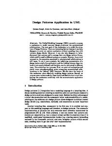
where η is a defined variable identifying how large a keyx can be obtained with a certain value of p. Considering the bulk silicon micro-fabrication process adopted in our laboratory, the initial gap d0 is most commonly chosen as 4 μm. Then with several different values of the comb width w, the influences of the gap ratio p on the value of the variable η are shown in Figure 5. In is obvious that with a proper design of gap ratio p, the variable η and then the electrostatic coupling stiffness keyx can be maximized within a limited available length Lqy. When the comb width w was chosen as 4, 6 and 8 μm respectively, the optimal values of p would be 2.36, 2.49 and 2.61.
0.040
0.0150
0.035
0.0125
0.030
0.0100
0.025
0.0075
dη/dp
η ( 1/μm )
Figure 5. (a) Change tendency of η with the variation of p; (b) Change tendency of dη/dp with the variation of p.
0.020
w = 4 μm w = 6 μm w = 8 μm
0.015 0.010
0.0050 0.0025 0.0000
0.005 0.000 1.0
w = 4 μm w = 6 μm w = 8 μm
-0.0025
1.5
2.0
2.5
3.0
3.5
4.0
4.5
5.0
-0.0050 1.0
1.5
2.0
2.5
p
(a)
3.0
p
(b)
3.5
4.0
4.5
5.0
Sensors 2014, 14
20431
4. Design and Analysis of Voltage Loading Methods
In the process of quadrature compensation, the regulation of the DC voltages relies on the change tendency of the quadrature vibration response yq with the variation of V1 and V2. The main influence of quadrature compensation on the dynamic equation in sense direction is the introduction of an electrostatic coupling stiffness keyx and a negative electrostatic stiffness key. With no input angular rate, the dynamic equation in sense direction during quadrature compensation can be expressed as: mc y + c y y + ( k y + key ) y = − ( k yx + keyx ) x
(33)
With Equations (5) and (33), the steady-state solution of the quadrature vibration response yq in the process of quadrature compensation can be expressed as: k y + key ω d − ( k yx + keyx ) Ad / mc m Q c s sin (ωd t − 90° + φ ) , φ = − arctan yq = 2 2 k y + key k k + k y + key ω − ωd 2 y ey 2 d − ωd + mc mc Qs mc
(34)
For the convenience of analysis, we named the upper half of the quadrature compensation patterns shown in Figure 3 as Group-1. It consists of basic structural units Type-A, Type-D and provides positive electrostatic coupling stiffness. Likewise, we named the lower half of the quadrature compensation patterns shown in Figure 3 as Group-2. It consists of basic structural units Type-B, Type-C and provides negative electrostatic coupling stiffness. Group-1 is applied with DC voltage V1 and Group-2 is applied with DC voltage V2. Generally, there are two voltage loading methods: (1) Single group loading. The sign of the mechanical coupling stiffness was firstly obtained through measuring the phase of the quadrature vibration response. Then according to the needed sign of the electrostatic coupling stiffness, positive or negative, only one group of the patterns, Group-1 or Group-2, was applied with a DC voltage. Through the regulation of this DC voltage, V1 or V2, the amplitude of the quadrature vibration response was reduced to zero. The voltage loading group was chosen manually. Hence this method is suitable for off-line compensation. (2) Double group loading. Both groups of the patterns, Group-1 and Group-2, were applied with DC voltages, V1 and V2. The sign of the electrostatic coupling stiffness, positive or negative, was decided by the relative size of V1 and V2. Through the regulation of |V12 − V22|, the amplitude of the quadrature vibration response was reduced to zero. Commonly, these two DC voltages were chosen as follows:
V1 = VD + Vq , V2 = VD − Vq , V12 − V22 = 4VDVq
(35)
where VD is the preset bias voltage and Vq is the regulation voltage. With a constant VD, the regulation of Vq can change both the sign and the value of the electrostatic coupling stiffness. Hence this method is suitable for on-line compensation. When single group loading was employed, assuming that the mechanical coupling stiffness was negative, with Equations (24), (27) and (34), the relationship between the amplitude of the quadrature vibration response |yq| and the applied DC voltage V1 can be expressed as:
Sensors 2014, 14
20432
yq =
− k yx + 2 ( nmd + nsd ) β ⋅ V12 Ad / mc 2
k y − 2 ( nmd + nsd ) γ l0 ⋅ V12 k y − 2 ( nmd + nsd ) γ l0 ⋅ V12 ωd 2 − ωd + mc mc Qs
2
(36)
When double group loading was employed, a constant bias voltage VD was preset. With Equations (24), (27), (34) and (35), the relationship between the amplitude of the quadrature vibration response |yq| and the regulation voltage Vq can be expressed as: yq =
− k yx + 2 ( nmd + nsd ) β ⋅ 4VDVq Ad / mc k y − 2 ( nmd + nsd ) γ l0 ⋅ 2 (VD 2 + Vq 2 ) k y − 2 ( nmd + nsd ) γ l0 ⋅ 2 (VD 2 + Vq 2 ) ω 2 d − ωd 2 + mc mc Q s 2
(37)
From Equation (36), it can be found that when single group loading was employed, |yq| has a non-linear relationship with V1. The natural frequency of the sense mode was directly affected by V1. It would change a lot in the process of quadrature compensation. From Equation (37), it can be found that when double group loading was employed, if the condition of VD >> Vq was met, the influence of Vq on the natural frequency of the sense mode can be alleviated greatly and |yq| would have an approximately linear relationship with Vq. Therefore, when a smaller change of the natural frequency or a linear relationship between the output and input signals was preferred in the process of quadrature compensation, double group loading would be superior to single group loading. No matter which voltage loading method was employed, the need quadrature compensation voltage is the one that makes the amplitude of the quadrature vibration response |yq| to be zero. When a voltage smaller than that one was applied, |yq| would be nonzero and the quadrature vibration response would be in the state of undercompensation. When a voltage larger than that one was applied, |yq| would also be nonzero and the quadrature vibration response would be in the state of overcompensation. 5. Application Example
The proposed design of quadrature compensation patterns shown in Figure 3 was applied on a dual-mass silicon micro-gyroscope developed in our laboratory. The structural schematic of this dual-mass silicon micro-gyroscope along with three local SEM photos of the basic structural units are shown in Figure 6. The structure of the dual-mass silicon micro-gyroscope is centrosymmetric. Either the left part or the right part of it can be seen as a full-decoupled single-mass silicon micro-gyroscope. The mechanical coupling of these two parts in the drive direction was realized by two folded beams designed between the left and right drive mechanisms. In operation, the left and right parts of this dual-mass silicon micro-gyroscope would vibrate in anti-phase mode and the sense-mode position signal would be obtained differentially. The mechanical structure of this micro-gyroscope was fabricated on (100) silicon wafer and a bulk silicon micro-fabrication process named Deep Dry Silicon on Glass (DDSOG) was adopted. The procedure of this fabrication process is shown in Figure 7.
Sensors 2014, 14
20433
Figure 6. Structural schematic of the dual-mass silicon micro-gyroscope with quadrature compensation patterns. Y z
X V1
V2
Anchors
Quadrature Compensation Patterns
Coriolis Mass
Sense Combs
Sense Mechanism V2 Drive Combs
V1 Drive Mechanism
Folded Beams
Figure 7. Fabrication process of DDSOG (Deep Dry Silicon on Glass).
The main design parameters are shown in Table 1. With Equation (26) it can be found that when the natural frequency of the drive mode is about 4 kHz and the DC voltage applied on a single pattern group is no more than 12 V, the compensation of a quadrature equivalent angular rate Ωq no more than 412 °/s can be realized theoretically by the proposed design.
Sensors 2014, 14
20434
Table 1. Design parameters of the dual-mass silicon micro-gyroscope with quadrature compensation patterns. Symbols mc Lmd Lsd nmd nsd h0 d0 p
Descriptions Coriolis mass Lever arm of the basic structural units in the middle part Lever arm of the basic structural units at the side parts Number of the basic structural units in the middle part Number of the basic structural units at the side parts Thickness of the structure layer Initial gap of the comb capacitors Gap ratio of the comb capacitors
Design Values 0.5 × 10⁻⁶ Kg 150 μm 1200 μm 40 5 60 μm 4 μm 2.5
6. Experimental Results
The dual-mass silicon micro-gyroscopes were vacuum sealed with ceramic packages after micro-fabrication. Off-line quadrature compensation was carried out on a silicon micro-gyroscope prototype to verify the correctness of the previous design and analyses. In the process of off-line quadrature compensation, the drive circuit worked normally. That is, in the drive direction, the two Coriolis mass were actuated into resonant vibration in anti-phase mode with the same constant amplitude. With no input angular rate, the drive-mode velocity signal and the sense-mode position signal were both extracted. In this condition, the sense-mode position signal was dominated by the quadrature vibration response yq. Hence, after measuring the amplitude of the sense-mode position, with Equation (9) and the scale factor of the silicon micro-gyroscope, the value of the quadrature equivalent angular rate Ωq was estimated. Then with Equation (26), the needed DC voltages were calculated theoretically. Meanwhile, through the comparison of the phase information between the drive-mode velocity signal and the sense-mode position signal, the sign of the mechanical coupling stiffness was obtained. According to the needed sign of the electrostatic coupling stiffness, proper pattern groups were chosen to apply the theoretical compensation voltages. After a fine regulation of the applied DC voltages, off-line quadrature compensation was realized. The experimental results of a silicon micro-gyroscope prototype showing quite large quadrature vibration response are presented here. The natural frequency of its drive mode is about 3.8 kHz. The value of its quadrature equivalent angular rate Ωq was estimated to be 357 °/s. The sign of its mechanical coupling stiffness was found to be negative. Therefore, with Equation (26), the theoretical compensation voltages were calculated to be |V12 − V22| ≈ 118.6 V2. When the voltage loading method of single group loading was employed, Group-1 was needed to be applied with a DC voltage of V1 ≈ 10.89 V theoretically. When the voltage loading method of double group loading was employed, with a preset bias voltage of VD = 10 V applied on both Group-1 and Group-2, the needed regulation voltage would be Vq ≈ + 2.97 V theoretically. The two voltage loading methods were both carried out and the experimental data of the relationships between the output amplitude of the sense-mode position signal and the applied DC voltages were obtained. At the same time, the theoretical curves of the relationships between the amplitude of the quadrature vibration response and the applied DC voltages were calculated from Equations (36) and (37). When the voltage loading method of single group loading was employed, the comparison of the experimental data and the theoretical curve was shown in Figure 8. It can be found that the change
Sensors 2014, 14
20435
tendency of the experimental data matched well with that of the theoretical curve. In the process of quadrature compensation, the quadrature signal has a non-linear relationship with the compensation voltage V1. The actually needed DC voltage for quadrature compensation was V1 ≈ 12 V, which is a little larger than the theoretical value. Figure 8. Relationships between the quadrature signal and the compensation voltage when the method of single group loading was employed. Theoretical Curve
Experimental Data 700
0.035
600
0.025
500
0.020 400 0.015 300
0.010
200
0.005 0.000 0
1
2
3
4
5
6
7
8
9
Experimental Output ( mV )
Theoretical Amplitude ( μm )
0.030
100 10 11 12 13 14 15
DC Voltage V1 ( V )
Figure 9. Relationships between the quadrature signal and the compensation voltage when the method of double group loading was employed. Experimental Data 700
0.030
600
0.025
500
0.020 400 0.015 300 0.010 200 0.005
Experimental Output ( mV )
Theoretical Amplitude ( μm )
Theoretical Curve 0.035
100
0.000 0.0
0.5
1.0
1.5
2.0
2.5
3.0
3.5
4.0
4.5
DC Voltage Vq ( V )
When the voltage loading method of double group loading was employed, the comparison of the experimental data and the theoretical curve was shown in Figure 9. It can be found that the change tendency of the experimental data also matched well with that of the theoretical curve. In the process of quadrature compensation, the quadrature signal has an approximately linear relationship with the
Sensors 2014, 14
20436
compensation voltage Vq. The actually needed DC voltage for quadrature compensation was Vq ≈ 3 V, which is also a little larger than the theoretical value. The drive-mode velocity and sense-mode position signals before off-line quadrature compensation are shown in Figure 10a, in which the upper wave is the drive-mode velocity and the lower one is the sense-mode position. The Lissajous figure before off-line quadrature compensation is shown in Figure 10b, in which the X-channel input is the drive-mode velocity and the Y-channel input is the sense-mode position. The two corresponding figures after off-line quadrature compensation are shown in Figure 11a and b. Figure 10. (a) The drive-mode velocity signal and the sense-mode position signal before quadrature compensation; (b) The Lissajous figure before quadrature compensation.
(a)
(b)
Figure 11. (a) The drive-mode velocity signal and the sense-mode position signal after quadrature compensation; (b) The Lissajous figure after quadrature compensation.
(a)
(b)
It is obvious that the sense-mode position signal has the same frequency as the drive-mode velocity signal. Before off-line quadrature compensation, it was dominated by the quadrature vibration response and had an approximately 90° phase lag with the drive-mode velocity signal. After off-line quadrature compensation, the quadrature vibration response was cancelled out. However, it could be seen that a residual sense-mode position signal still existed. Its amplitude was about 100 mV in the tested silicon micro-gyroscope prototype. This residual signal had the same phase with the drive-mode velocity signal and is commonly named as in-phase error. It is mainly caused by other mechanisms, e.g. the viscous coupling between drive mode and sense mode.
Sensors 2014, 14
20437
7. Conclusions
Quadrature reduction is one of the primary issues in the design of high-performance silicon micro-gyroscopes. Among the various quadrature reduction methods, system stiffness matrix diagonalization has its peculiar advantages. In this method, with purposefully designed quadrature compensation patterns and properly applied DC voltages, an electrostatic coupling stiffness is electromechanically constructed to cancel out the mechanical coupling stiffness which is the main cause of the quadrature vibration response. This paper focus on the detailed design issues of this method and presents a complete design and application case. For bulk silicon micro-gyroscopes, the quadrature compensation patterns which consist of comb capacitors are more suitable than those consisting of parallel plate capacitors because they provide a better overall compensation capability. There are four types of basic structural units in the mechanical design of quadrature compensation patterns. With an applied DC voltage, they can generate negative or positive dynamic electrostatic forces in sense direction. These dynamic forces are proportional to the drive-mode position, hence the needed positive or negative electrostatic coupling stiffness can be provided. Besides the useful dynamic forces, the basic structure units also generate additional static forces and torques which may cause a disturbance. A novel layout design was proposed to solve this problem. The basic structural units distributed at different places can provide same-directional dynamic forces, opposite-directional static forces and opposite-directional static torques. The opposite-directional static forces were designed to have the same absolute value. Hence no net static force exists. The opposite-directional static torques were also made to have the same absolute value. Hence no net static torque exists. When the available values of the applied DC voltages are limited, an optimization of the structural parameters, especially the gap ratio, can help improving the quadrature compensation capability. In the process of quadrature compensation, there are two voltage loading methods: single group loading and double group loading. Single group loading is more suitable for off-line quadrature compensation. When it is employed, the quadrature signal has a non-linear relationship with the compensation voltage in the compensation process. The natural frequency of the sense mode is directly affected during the regulation of the compensation voltage. Double group loading is more suitable for on-line quadrature compensation. When it is employed, the quadrature signal has an approximately linear relationship with the compensation voltage in the compensation process. The influence of the compensation voltage regulation on the natural frequency of the sense mode can be alleviated. The proposed design of quadrature compensation patterns was applied on an actual dual-mass silicon micro-gyroscope developed in our laboratory. With the DC voltage applied on a single pattern group no more than 12 V, the theoretical compensation capability of a quadrature equivalent angular rate no more than 412 °/s was designed. In the experiments carried out on a packaged micro-gyroscope prototype, an actual quadrature equivalent angular rate of 357 °/s was compensated. The values of the actual compensation voltages were a little larger than the theoretical ones. The correctness of the design and the theoretical analyses was verified. They can be commonly used in planar linear vibratory silicon micro-gyroscopes for quadrature compensation purpose.
Sensors 2014, 14
20438
Acknowledgments
This work is supported by the fund 9140A09011313JW06119 and BE2014003-3, the National Natural Science Foundation of China (No.61101021), the Jiangsu Provincial Natural Science Foundation of China (No.BK2010401), and the Foundation of Key Laboratory of Micro-Inertial Instrument and Advanced Navigation Technology, Ministry of Education, China (No.KL201103). Author Contributions
This work is carried out in collaboration among all authors. The authors defined the research theme together. Libin Huang provided the theoretical analysis guidance. Yunfang Ni carried out the theoretical analyses and mechanical design. Hongsheng Li conceived and designed the experiments. Yunfang Ni analyzed the experimental results and wrote the paper. All authors have contributed to, reviewed and approved the manuscript. Conflicts of Interest
The authors declare no conflict of interest. References
1. 2. 3.
4.
5.
6. 7.
Saukoski, M.; Aaltonen, L.; Halonen, K.A.I. Zero-rate output and quadrature compensation in vibratory MEMS gyroscopes. IEEE Sens. J. 2007, 12, 1639–1652. Acar, C.; Shkel, A. MEMS Vibratory Gyroscopes: Structural Approaches to Improve Robustness; Springer-Verlag: New York, NY, USA, 2009; pp. 93–102. Clark, W.A.; Howe, R.T.; Horowitz, R. Surface micromachined z-axis vibratory rate gyroscope. In Proceedings of the IEEE International Solid-State Sensor and Actuator Workshop, Hilton Head Island, SC, USA, 3–6 June 1996; pp. 283–287. Chaumet, B.; Leverrier, B.; Rougeot, C.; Bouyat, S. A new silicon tuning fork gyroscope for aerospace applications. In Proceedings of Symposium Gyro Technology, Karlsruhe, Germany, 22–23 September 2009. Zaman, M.F.; Sharma, A.; Hao, Z.; Ayazi, F. A mode-matched silicon-yaw tuning-fork gyroscope with subdegree-per-hour Allan deviation bias instability. J. Microelectromech. Syst. 2008, 17, 1526–1536. Sharma, A.; Zaman, M.F.; Ayazi, F. A sub-0.2°/hr bias drift micromechanical silicon gyroscope with automatic CMOS mode-matching. IEEE J. Solid-State Circuits 2009, 44, 1593–1608. Tatar, E.; Alper, S.E.; Akin, T. Quadrature-error compensation and corresponding effects on the performance of fully decoupled MEMS gyroscopes. J. Microelectromech. Syst. 2012, 21, 656–667.
© 2014 by the authors; licensee MDPI, Basel, Switzerland. This article is an open access article distributed under the terms and conditions of the Creative Commons Attribution license (http://creativecommons.org/licenses/by/4.0/).