Carnegie Mellon University
Research Showcase Robotics Institute
School of Computer Science
5-1-2012
Design and Architecture of the Unified Modular Snake Robot Cornell Wright Carnegie Mellon University
Austin Buchan Carnegie Mellon University
Ben Brown Carnegie Mellon University
Jason Geist Carnegie Mellon University
Michael Schwerin Carnegie Mellon University See next page for additional authors
Follow this and additional works at: http://repository.cmu.edu/robotics Part of the Robotics Commons Recommended Citation Wright, Cornell; Buchan, Austin; Brown, Ben; Geist, Jason; Schwerin, Michael; Rollinson, David; Tesch, Matthew; and Choset, Howie, "Design and Architecture of the Unified Modular Snake Robot" (2012). Robotics Institute. Paper 762. http://repository.cmu.edu/robotics/762
This Conference Proceeding is brought to you for free and open access by the School of Computer Science at Research Showcase. It has been accepted for inclusion in Robotics Institute by an authorized administrator of Research Showcase. For more information, please contact
[email protected].
Authors
Cornell Wright, Austin Buchan, Ben Brown, Jason Geist, Michael Schwerin, David Rollinson, Matthew Tesch, and Howie Choset
This conference proceeding is available at Research Showcase: http://repository.cmu.edu/robotics/762
Design and Architecture of the Unified Modular Snake Robot Cornell Wright, Austin Buchan, Ben Brown, Jason Geist, Michael Schwerin, David Rollinson, Matthew Tesch, and Howie Choset {cgwright, abuchan, hbb, jgeist, mbs2, drollins, mtesch, choset}@andrew.cmu.edu
Abstract— The design of a hyper-redundant serial-linkage snake robot is the focus of this paper. The snake, which consists of many fully enclosed actuators, incorporates a modular architecture. In our design, which we call the Unified Snake, we consider size, weight, power, and speed tradeoffs. Each module includes a motor and gear train, an SMA wire actuated bistable brake, custom electronics featuring several different sensors, and a custom intermodule connector. In addition to describing the Unified Snake modules, we also discuss the specialized head and tail modules on the robot and the software that coordinates the motion.
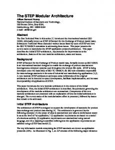
I. I NTRODUCTION Snake robots are hyper-redundant (many degree of freedom) mechanisms consisting of a series of joints which move via internal shape changes like a snake [1]. The narrow miminum cross section of a snake robot and extreme range of motion of its joints allow it to navigate many diverse environments, such as uneven ground, slopes, channels, pipes, poles, and trees as in Figure 1. This makes them applicable to diverse tasks such as urban search and rescue, mine rescue, industrial inspection, and reconnaissance. The harsh environments of these applications require a strong, reliable robot. We have designed a rugged, fully enclosed, modular robot architecture based on the refinement of our previous snake robot designs [2][3]. This architecture, which we call the “Unified Snake,” incorporates an advanced mechanical design along with cutting-edge electronics and software to produce a robot which has withstood the test of numerous deployments. Table I shows the specifications of the Unified Snake robot. Power Data Video
Sensors
Actuators Torque Mass Dimensions
36 V, 1.5 A (typical) 8.0 A (theoretical max) RS-485 Serial Analog NTSC 3-axis Accelerometer 3-axis Gyroscope Temperature Voltage Motor Current Joint Angle 36 V Brushed DC Motor SMA Wire Parking Brake 1.3 Nm (0.95 ft lb) Continuous One Module: 0.16 kg (0.35 lb) Full 16 Module Robot: 2.9 kg (6.5 lb) 5.1 cm (2.0 in) Diameter x 94 cm (37 in) Length
TABLE I: Unified snake robot specifications.
Fig. 1: Photograph of the Unified Snake Robot climbing a tree.
II. R ELATED W ORK Shigeo Hirose provides a very good overview of several snake robots as well as some discussion on snake kinematics [4]. Notable robots he describes include several iterations of the Active Cord Mechanism (ACM) and the Slim Slime robot. Some of the ACMs have wheels on every module while others are sealed such that they can locomote under water. Like the Unified Snake, the ACM-R5 is fully enclosed and designed for rugged field operation. The Slim Slime has joints which use pneumatics to bend and elongate. Øyvind Stavdahl et. al. of the Norwegian University of Science and Technology have produced a snake robot which includes a contact force measurement system on each module [5]. The snake has spherical shaped modules and uses interaction with obstacles to aid its locomotion. Inside each 2-DOF module are two hobby servos, magnetic encoders, and a Lithium Ion Battery. The modules communicate over CAN bus and the head includes a wireless camera and infrared rangefinder. Each module also incorporates force sensing resistors in order to provide one point of contact force measurement for that module [6]. Johann Borenstein has made several versions of Omnitread which is a snake-like robot with tracks on the outside of every joint [7]. At 4-8 inches (10.16-20.32 cm) diameter (depending on model), the joints are physically larger than the Unified Snake, and bend with pneumatic bellows. The head and tail of one model, the OT-4, have flippers which extend the reach of the treads. Like the Unified Snake, the
later models of Omnitread are designed for rugged real-world operation. Mark Yim’s Polybots [8][9][10] are versatile modular robotic systems that feature 1-DOF joints and two connecting ports per segment. The 2in × 2in × 2in modules allow the robot to support a number of configurations which include snake, spider, and rolling modes. One special module that they call a node has 6 connecting ports to allow more than two segments to join together. The Modlab has also produced a brake for modular robots [11]. We discuss this more in § III-C. III. M ECHANICAL OVERVIEW Each module from the Unified Snake is rigid and contains two 1-DOF half-joints, each connecting to the next and previous modules. Each joint allows a full 180◦ of rotation. The actuated axis of each module is rotated 90◦ around the spine of the robot relative to the actuated axis of the preceding module. Including specialized head and tail modules, the typical robot has 16 degrees of freedom (although more modules can be added if needed), with the actuated axes alternately aligned with the robot’s lateral and dorsal planes. The modules are 2 inches (5.08 cm) in diameter, and 2 inches (5.08 cm) between joint axes.
Fig. 3: Assembly drawing of a Unified Snake Robot module showing the three components of the housing.
provides better locomotion in gaits which utilize rollingcontact such as pole climbing and rolling arc [12]. The Unified Snake module housing consists of three segments, shown in Figure 3. The lower housing contains the mounting points for all of the internal components, including the motor and gearbox, control board, brake, module connector and output hub. It is sandwiched between the upper housing and the cap with machine screws. The upper housing serves as a cover for the motor and brake and includes a double o-ring bore seal for the output hub. The cap provides a cover for the control electronics. B. Drivetrain
Fig. 2: Key components of a Unified Snake Robot module. As seen in Figure 2, the key portions of each module are the housing, the motor and gearbox, a bi-stable brake, and the intermodule connector. The housing is an aluminum shell which contains the rest of the parts which make up the module. The motor and gearbox provide the rotary torque for the powered half-joint. A bi-stable brake is present to allow the output hub of the module to hold in place without consuming power or generating heat. The intermodule connector provides the electrical connection between modules and holds a magnet which is used to provide joint position feedback. A. Housing Our previous Super Servo 1 [2] and Super Servo 2 [3] versions of the snake robots had an octagonal cross section. This was necessary to accommodate the square cross-section of the hobby servo without adding additional diameter. On the Unified Snake we chose a round cross section, which
A 36V brushed DC Maxon motor is used with a custom metal gear-train consisting of a pinion gear on the motor and three compound gears to drive the output hub in the module. This gives a gear reduction of 401:1. Under no load the motor is rated to turn at 11,500 RPM, which would result in 28.7 RPM at the output. Experimentally we found an unloaded speed of 26.1 RPM at the output (which translates to 10,480 RPM at the motor). The torque produced at the output of the module is 1.3 Nm (0.95 ft lb). This translates to 3.4mNm (oz in) at the motor or losses of 10% in the gearbox, given the 3.76mNm (0.52 oz in) continuous torque rating of the motor. Experimentally we have determined the holding torque of the module to be 2.71 Nm (2 ft lb). This represents the most torque that can be loaded onto the module while commanding it to maintain its current position before back-driving occurs. A slip clutch is also present to protect the gears from overload due to external forces, particularly when the brake is engaged. This could happen, for example, if the robot were to fall from a large height. The clutch consists of preloaded belleville washers that push the bottom of the pinion gear against a hub bonded onto the end of the motor output shaft. In the event of excessive torque the clutch slips preventing damage. The clutch is designed to slip at 17mNm (2.41 oz in) of torque at motor output gear. Assuming a 100% efficient gearbox, this would be 6.8 Nm (5 ft lb) at the module’s output hub. Because joint position feedback is at the output of the gear train, any clutch slippage does not require recalibration when the external forces are removed.
Size Mass Actuation Energy Holding Torque at Output1 Actuation Time Relaxation Time Max. Frequency2
1.6 x 3.5 x 2.0 cm (0.63 x 1.38 x 0.79 in) 6.1 g (0.22 oz) 143 mJ > 6.8 Nm (5 ft lb) 1.94 ms 750 ms 1.33 Hz
TABLE II: Bistable brake performance characteristics. Fig. 4: Unified Snake module motor and brake assembly. to cool the SMA and recharge the energizing capacitor leads to a lower maximum actuation frequency. C. Brake Our goal in incorporating a brake mechanism with the Unified Snake was to have each module contain a bi-stable parking brake, which takes energy to engage or disengage, but requires no power to hold the module in a position or allow the module to move freely. This allows the robot to stay locked in position, say in the top of a tree for surveillance purposes, with no motor actuation consuming power. Furthermore, due to the bi-stable nature of the brake (and the electronics we describe in § IV-B), it is possible for the user to set the desired power-fail state (engaged/disengaged) of the brake. In the event that power is removed, the brake will engage or disengage if necessary to be in the desired state. In some situations, such as when climbing a tree, the best response to a power failure is to engage the brakes since falling could damage the robot and potentially injure people below. In others, such as inspecting pipes in a power plant, it is better to disengage the brakes to make it easier to remove the robot and minimize the potential for costly power plant down time. Figure 4 shows all of the parts which make up the brake. A PCB (described in § IV-B) is mounted to the motor, providing the mechanical structure for the brake as well as the electronics to actuate it. When the brake is engaged a pawl on the spring lever engages with teeth on the parking gear mounted on the rear shaft of the motor. This prevents the motor and gear train from moving and locks the module in position. The spring lever is engaged and disengaged by a pair of shape memory alloy (SMA) wires. When the appropriate SMA wire contracts, it pulls the spring lever in the desired direction. The spring lever is held in place by the attached toggle spring while neither of the SMA wires is being actuated. In this manner, energy is only required to engage or disengage the brake. Table II shows the operating characteristics of the brake. Compared to alternative designs using magnetic or piezoelectric (PZT) actuation modalities, this design offers much higher holding torque for its size, weight, and power usage [11]. While the actuation time is much faster than other designs (and comparable to PZT), the relaxation time required 1 Clutch-limited 2 For
holding torque. alternate braking and releasing actuations.
D. Connector Due to mechanical constraints and in order to improve modularity of the robot we created custom donut-shaped connectors to pass all power and data between modules. The connector is located along the axis of rotation of each module. Inserting this connector and then installing 4 screws is all that is needed to connect two modules. A custom design was needed to accommodate the coaxially mounted diametrically polarized magnet used to measure angular position of the joint as well as the 2 power connections (rated at 8 amps each) and 7 data/shield connections all within an 7/16in (11.1mm) diameter circle.
Fig. 5: Closeup picture of electrical connection between two Unified Snake modules. Figure 5 shows a closeup view of the connection between two modules. The stalk holds the connector body inside the previous module to allow it to mate at the proper depth. Male pins on the control board contact female pins in the connector body, creating an electrical connection. The connector body can rotate freely around the stalk, and wires (not shown) connect from the female pins to the control board, traveling along the stalk. In this manner the module’s 180◦ of bending mainly creates a twisting action in the wires, resulting in very little length change or fatigue. A diametrically polarized magnet is also rigidly attached to the stalk such that as the joint turns the magnet rotates with it. On the underside of the control board a magnetic encoder integrated circuit (IC) reads the direction of the magnetic field and uses this to provide angular position feedback.
E. Skins In order to provide traction and a degree of compliance we attach skins to the outside of the housings. Both 3-D printed screw-fastened skins and adhesive-backed rubber skins have been designed and used extensively on the robot. 1) 3-D Printed: We designed screw-fastened skins for the Unified Snake to be manufactured on a 3-D printer capable of printing multiple durometer materials. The outer face of the printed skin was a soft urethane material layered around a more rigid plastic which attached to the module with countersunk screws. Figure 6(a) shows a model of the 3-D printed screw-fastened skin.
end with a camera module, and a tether adapting tail at the other. Each standard module has a main control board that handles communication with control software on the main bus, gathers sensor data, and executes closed-loop position control of the joint angle. A secondary brake/motor board handles the operation of the brake and direct control of the motor based on commands from the control board. Conductors for 36 volt power, RS-485 communications, and analog video from the head module run from the tether throughout the length of the snake via the inter-module connectors. Power and serial communications are carried through a flat-flex cable from the control board to the brake board within each module. A. Sensing
(a)
(b)
Fig. 6: Various skins for the snake robot: (a) Model of 3D printed screw-fastened skin and (b) Exploded view of a module with adhesive backed skins. The 3-D printed skin has several weaknesses including a relatively low coefficient of friction and fast wear, especially in rough outdoor environments. The plastic base also cracks easily under impacts, which results in pieces of skin falling off of the robot. Furthermore, since the skin slides over the module as one piece it made assembly and disassembly of the robot much more difficult as it needed to be removed to open a module or disconnect from other modules in the robot. 2) Adhesive-backed Rubber: We later designed adhesive backed silicone rubber skins to attach directly to the outside of the modules. This provided better friction characteristics and did not have the cracking issues of the 3-D printed skins. By designing multiple pieces that match the seams in the housing sections, this design also allows modules to be disassembled without removing the skin. Figure 6(b) shows a module with the adhesive backed skins. Although they are more rugged than the 3-D printed skins, the silicone skins do slowly peel and become damaged by use in rough environments. Periodic cleaning of the robot and replacing worn out skins solves this issue. Currently, the adhesive-backed rubber skins are the preferred skins for general use of the robot. IV. E LECTRONICS OVERVIEW The Unified Snake robot consists of a chain of several (usually 16) standard 1-DOF modules terminated at one
Several sensors are present in each Unified Snake module. These include a three-axis accelerometer and gyroscope, temperature, humidity, motor current, and module position sensors. The inertial sensors (accelerometer and gyroscope) are used to determine the direction of gravity (i.e. which side of the robot is “up”), allowing the control software to modify the motion of the robot accordingly. Also research into using the sensors to solve various state estimation problems is ongoing in the Biorobotics Lab [13]. The microcontroller in the module constantly monitors values from the temperature sensor to prevent overheating of the module. In the event that a temperature limit is exceeded, power to the motor is removed. In previous versions of the robot this was a significant issue. However, by going to a higher efficiency and higher voltage motor this problem has been resolved. Overheating now only occurs when operating for a long time in a very hot environment, or performing very strenuous motions. Motor current is monitored in order to allow for limiting current to the motor as a rough way to control force output. Also by monitoring the current a user can determine which modules are having to work harder to perform a particular motion. Module position feedback is provided by a magnetic encoder and is clearly necessary for motion control. By monitoring the actual position of a module compared to the commanded position, the user receives some information on how the environment is affecting the shape of the robot. The encoder reads the position of the output hub directly, so gear backlash does not affect the accuracy of the joint angle measurements. Finally a humidity sensor was installed as part of the initial design in an attempt to detect water ingress into the modules. Unfortunately, due to lack of airflow within the module this sensor does a poor job at detecting water ingress and will probably be removed from future designs. B. Brake Actuation and Motor Control Our primary goals in implementing a modular brake were to be able to reliably command a locked or free state for each module, and especially to be able to actuate to a configurable
36V
Charge Control/ Isolation
Brake SMA Release SMA
Energy Storage Capacitor
To microcontroller
An externally threaded connection with a bore seal o-ring allows various head payloads to be mechanically connected to the robot. Internal to the head adapter is a 10-pin connector that provides power, communications, and video lines to whatever device is attached to the head. Figure 8(a) shows the modular head adapter.
Fig. 7: Brake actuation schematic.
state in the event of a power failure. Secondary to these were minimizing power consumption, actuation time, and physical space taken up by the mechanism. Additionally, the device must operate within the voltage and current limits allowed in each module. Among electromechanical, piezoelectric, and SMA actuation options we considered, SMA had the greatest force to volume ratio, making it attractive for integration to an already tightly constrained mechanical design. However, traditional electrical heating control of SMA actuators involves applying a constant current that will not damage the actuator in the heated steady-state, which would put a heavy load on our regulatory electronics. This approach also does not guarantee actuation in power failure. Instead, we used a low-ESR capacitor that that stores the energy necessary (plus a safety margin) to transition the SMA wire to the contracted phase. When command to change state, the capacitor is isolated from the supply and connected across the appropriate SMA element, resulting in very fast actuation. The capacitor is recharged at a controlled current during the thermal relaxation phase of the SMA wire. By maintaining this charge during normal operation, the device can activate the brake if necessary on a power failure, provided the brake has not transitioned within the relaxation time of the power failure. Figure 7 shows a schematic of the actuation electronics. The brake unit also includes an optical sensor that detects the position of the pawl arm. This allows for the state of the brake to be sensed on startup and controlled on the position of the arm in the event of a failed actuation (from pawl misalignment) or accidental release (from large physical shock to a module). Along with the brake actuation, the brake board also contains the motor driver circuit. This is accomplished with a simple off the shelf motor driver IC. The processor on the brake board commands the motor to a specific PWM duty cycle which it receives via a serial interface from the processor on the control board. V. H EAD AND TAIL M ODULES A. Head Module 1) Modular Adapter: On the head of the robot is a modular head adapter. This consists of one non-powered halfjoint with an intermodule connector to the previous module.
(a)
(b)
Fig. 8: (a) Modular head adapter and (b) full camera assembly. 2) Camera: For most applications the desired payload on the head of the snake robot is a camera with its own LED illumination. We have designed a camera module which connects to the head adapter providing video through a dedicated analog video bus and LED illumination of variable intensity controlled over the communications bus. The camera module is sealed to prevent ingress of water and dust. Figure 8(b) shows the camera module attached to the head adapter. B. Tail On the tail of the snake a specialized module is connected which contains a slip ring and connection to the tether. The slip ring is necessary to prevent twisting of the tether, particularly in rolling or pole climbing gaits. Some versions of the tail have also contained a small camera to allow the user to lift up the tail and see the front portion of the snake robot. VI. S OFTWARE AND C OMMUNICATIONS A. High Level Motion Control The Unified Snake robot is fundamentally a real-time embedded network with two major functions: execute motion control commands, and report sensor feedback information. From a control perspective, there must be low latency and high accuracy for motion control information to and from the robot modules. From a research perspective, we want the communication architecture to be flexible enough to support a variety of configurations and feedback information, while being extensible enough to add new types of information as new sensors or control parameters are introduced to the modules. It is also important that the network adapt to different numbers and types of modules in the snake robot, or even extend to branched or cyclic configuration for the robot. Finally, all of these functions must be implemented with the
limited memory, communication bandwidth, and processing power available in the robot modules. Our communication architecture implementation solves these issues using a hierarchical network structure with clear master/slave relationships between processing units at each level of the network, and a messaging protocol supporting this multi-level addressing while keeping latency for time-critical information low.
Fig. 9: The controlling PC software is divided into several separate processes which each perform a particular function; this diagram shows a simplified set of these processes along with the LCM channels they subscribe to and publish on. The modularity enables easier debugging, less intrusive logging, and a high degree of flexibility – a subset of the modules can be run and others added seamlessly. For example, the Ethernet process can be replaced by a process which controls a computer simulation instead of the robot, and the remaining processes remain unaffected. Currently all position command information, making up the gaits executed on the snake robot [12], is generated by supervisory software running on a PC. This control software also collects feedback from the snake to display state information, and logs the data for later analysis. This software, which we call Snake Control, is modularized into a set of processes to allow the software to be more easily maintained, as well as making a very extensible and reconfigurable framework for controlling the robot (see Fig. 9). The communication between these processes is done using the open source Lightweight Communications and Marshalling library (LCM) [14], which is a UDP-based publisher/subscriber protocol. It is cross-platform, works for high-bandwidth data, and has bindings for C, C++, Python, Java (and derivatives such as MATLAB). The standard set of processes used by Snake Control to control the robot include the following: • Gait process: This generates module position commands at a specified rate. It listens on certain channels for transition commands that would switch the current gait, and for commands that would modify the variables in the equation of the current gait. • Ethernet process: Information to be sent to the snake, such as angle commands, are aggregated from their given channels, and sent to the snake through an
intermediate Ethernet repeater board over a standard Ethernet/UDP connection. The choice of Ethernet allows these packets to be understood by a custom Wireshark [15] plug-in for simple debugging. The Ethernet process also ensures requests for feedback are sent at a configurable rate, and provides a mechanism to guarantee delivery of protocol parameters (see § VI-D) such as head LED brightness over an unreliable UDP connection by continuing to send them until appropriate feedback has been received. • User interface: The user interface, written with the WxWidgets toolkit, provides the main interface for the human operator. It provides a visualization of feedback sent from the snake, and run-time loadable mappings written in a simple scripting language encode joystick and keyboard commands into actions that control other processes or the snake itself. • Log process: All the messages that are sent through LCM are saved into a binary log file, which generates human-readable CSV files upon program termination. These CSV files can be easily parsed by MATLAB to post-process data, and the binary log files can be replayed using standard LCM scripts, providing a powerful and simple replay feature for control or debugging. The ease of reconfigurability is demonstrated by a simple example: suppose a researcher developing a new motion based on a complex minimization coded in MATLAB wanted to test the motion on the physical robot. Rather than adding a new motion to the gait process, the researcher must only write a few of lines of MATLAB code. This code can then be run with the remaining Snake Control components to drive the robot. Furthermore, if someone was implementing a filter to process feedback in real time, they could simply listen on the appropriate feedback channel(s), and process the data as each packet arrives, while making no changes to the existing control code. After receiving a packet from the PC, the Ethernet board then handles sending the sequence of packets to individual module control boards over the RS-485 bus. Module position commands and requests for feedback are generated at about 25Hz for a 16-link robot. B. Low Level Motion Control As in previous designs, along with using PID control to regulate the position of the module, the position controller can also limit the electrical current drawn by the motor. This is achieved by maintaining a duty cycle limit on the motor which is then increased or decreased when the motor current is above or below the current limit. Due to the essentially linear relationship between current draw and torque, limiting current effectively creates a torque limit; this limit allows the snake robot to comply with the external environment and helps keep the motor from overheating when it is stalled. We have found that using a mostly proportional PID controller allows for compliance with the environment which is often desirable, particularly in cases of uneven or unknown terrain. Future software changes will allow scheduling of PID
gains via Parameter updates to allow the user to change the behavior of the position control depending on what motion is being executed or the environment that the robot is operating in.
0x11 0xE8 0x03
Payload
Destination Source Payload Size PL_SET_POSITION Position Data (1000)
0x15 PL_FEEDBACK_REQUEST 0xA0 Request Flags (current, 0x05 accel, gryo, pos) 0x80 CRC-16 0x15
CRC
Fig. 11: Example network packet. Ethernet Board Header
Control Board #1
Payload …
Header Payload …
CB #2 …
Packet List
CB #1 Packet List
C. Communications The main functions of the Unified Snake modules are to execute motion commands and report sensor feedback. To ensure that these features get priority in network communication, all transactions are initiated by a clearly defined master on each physical network, with slave units at a lower network level responding only when addressed by the master. Figure 10 shows this topology with the three network levels present in typical usage where the Unified Snake is controlled by a PC through an Ethernet adapter board. This simplifies addressing and prevents the need for collision management. A timeout is specified at each layer of the network to ensure that malfunctioning modules do not hinder the operation of the entire snake. Acknowledgements are not used by default under the assumption that the frequency of data being lost or corrupted is much lower than the frequency of data request.
0x07 0x00 0x06
Header
BB
Brake Board Header Payload … CRC
CRC
CB #N CRC
Fig. 12: Packet structure for sub-network addressing. E. Network Addressing
Fig. 10: Typical snake network communications topology. 1) Packets: A packet is a stream of bytes that is transmitted atomically on any of the physical network layers. All packets have three main sections: Header, Payload, and CRC. Figure 11 shows a sample packet from an Ethernet Board to a Control Board (with address 7) commanding a position and requesting standard feedback. The header of the packet contains the destination, source, and size of the payload. The payload section contains one or more of several defined payloads, in this case a position command and a request for sensor feedback. Finally the CRC section is used to verify the data integrity of the packet. D. Parameters To adjust operating configurations that change less frequently than motion setpoints or sensor feedback, a standardized Parameter framework has been implemented on all Unified Snake processing units. Parameters also offer the ability to store their values to EEPROM, so that their values are retained across power down cycles. Examples of Unified Snake Parameters include module current and temperature limits, PID gains for position control, and camera module illumination LED brightness.
In order to keep processing overhead low on the embedded devices, packets to a device on a sub-network level are embedded byte-for-byte in a higher level packet. This is convenient since the size of each sub-packet can be inferred from the size field, and efficient since the embedded device doesn’t have to recompute the CRC. Sub-device addresses are also inferred from the destination field of the header in the subpackets. The end of data intended for a device and the beginning of subpackets is delineated with a special Packet List payload type. Figure 12 shows how the tree structure of the snake network topology is flattened into a packet structure for sub-network addressing. This allows any arbitrary unit on the network to be addressed, with intermediate nodes only needing to forward complete subpackets. VII. R ELIABILITY Our previous work has examined reliability of the modular snake robots. In this section we describe a number of ways in which reliability has been improved over previous designs and where there is still room for improvement. A. Mechanical Many mechanical changes were made over the Super Servo 2 [3] in the design of the Unified Snake. The Super Servo 2 design relied on heavily modified off the shelf hobby servos as a large part of the mechanical design. This caused the design to essentially be an adaptation which was not fully suited to our applications as well as leaving us with many of the shortcomings of using hobbyist parts. In the Super Servo 2 design, one common point of failure was a nylon gear within the servo. By designing our own gearbox for the Unified Snake and doing analysis to ensure our gears could handle the expected loads, we have not
experienced gear failures. Furthermore, the addition of the clutch protects the gears. In this design we went to having all parts of the module fully enclosed. Any exposed wiring or connectors (even minimally exposed, high flexibility silicone insulation) are subject to abrasion and snagging, resulting in damage. Furthermore, in this design we routed the wires through the center of rotation of the joints, This allows the wires to undergo minor twisting during joint motion instead of large bending, and removes the need for service loops to compensate for length change. Future places to improve mechanical reliability mainly center around the design of the connector and the brake. The connector in the Unified Snake is somewhat fragile, due to the tiny pins, and the lack of alignment features common in off the shelf blind-mate connectors. A connector where more rugged mechanical features engaged before the fragile electrical connection would be desirable. The brake assembly process has proved to suffer from high variability due to such small and complex components being assembled by hand. Tolerance stack-up and imprecision in steps such as bending the pawl spring can lead to a large amount of hand-tuning necessary to produce a functional and reliable brake unit. However, once an individual brake reaches the point of operating reliably, it is stable over time. So far the only observed failure modes have involved the mechanism creeping out of mechanical alignment, or the wires pulling out of the crimp attachments. In future designs we hope to reduce the assembly time and improve the reliability of the brakes with a more automated assembly process. B. Electronics Changing to a higher quality, higher voltage motor greatly simplified and improved the electronics. Because a higher voltage motor requires less current for the same force output, we were able to switch to off-the-self motor driver ICs. While the Super Servo 2 discrete H-bridge failed very rarely, we have yet to see any motor drivers fail on the Unified Snake. The electronics in the Unified Snake are largely self protecting against both internal an external faults. Like the Super Servo 2, they have temperature and current limiting, as well as a fault-tolerant RS485 bus. However, we have also added circuitry to protect against over-voltage, reversed voltage and over-current conditions, which disconnects power to the module if a fault is detected. VIII. C ONCLUSIONS AND F UTURE W ORK We have presented an architecture for a robust, capable, and reliable modular snake which is useful both as a research platform and in the field. In designing the Unified Snake, we considered many factors such as module torque, size, weight, power, and sensor requirements. The result is a design with a high torque output per module, small module size and weight, and more efficient use of available power. In addition to this, we created a bistable brake which allows a snake robot module to hold its position without drawing any power.
While the Unified Snake design is very capable, we are still looking at several improvements. We are considering adding series elasticity between the modules to give the robot a mechanical compliance with the environment as well as provide us with an accurate means for dynamic force sensing. We are investigating adding external forward locomotion capability to the robot, similar to Omnitread’s treads and legs [7]. On our current robots we are also looking at adding intermediate payload modules to allow additional sensing to be added within the body of the robot. Finally, new head and tail modules can increase the capabilities of the robot. IX. ACKNOWLEDGEMENTS The authors gratefully acknowledge the contribution of all of the members of the Biorobotics Lab who helped construct and maintain the Unified Snake robot. Also, many thanks to Peggy Martin for helping procure materials and work with vendors. R EFERENCES [1] S. Hirose, Biologically Inspired Robots: Serpentile Locomotors and Manipulators. Oxford University Press, 1993. [2] C. Wright, A. Johnson, A. Peck, Z. McCord, A. Naaktgeboren, P. Gianfortoni, M. Gonzalez-Rivero, R. Hatton, and H. Choset, “Design of a modular snake robot,” in Intelligent Robots and Systems, 2007. IROS 2007. IEEE/RSJ International Conference on, pp. 2609 –2614, 2007. [3] A. Johnson, C. Wright, M. Tesch, K. Lipkin, and H. Choset, “A Novel Architecture for Modular Snake Robots,” tech. rep., Robotics Institute, 2011. [4] S. Hirose and H. Yamada, “Snake-like robots [tutorial],” Robotics Automation Magazine, IEEE, vol. 16, pp. 88 –98, march 2009. [5] P. Liljeb¨ack, K. Pettersen, and Ø. Stavdahl, “A snake robot with a contact force measurement system for obstacle-aided locomotion,” in Robotics and Automation (ICRA), 2010 IEEE International Conference on, pp. 683–690, IEEE, 2010. [6] P. Liljeb¨ack, S. Fjerdingen, K. Pettersen, and Ø. Stavdahl, “A snake robot joint mechanism with a contact force measurement system,” in Robotics and Automation, 2009. ICRA’09. IEEE International Conference on, pp. 3815–3820, IEEE, 2009. [7] G. Granosik and J. Borenstein, “Serpentine Robots for Industrial Inspection and Surveillance,” Industrial Robotics., pp. 633–662, February 2007. [8] D. G. Duff, M. Yim, and K. Roufas, “Evolution of PolyBot: A Modular Reconfigurable Robot,” in Proceedings of the Harmonic Drive International Symposium, 2001. [9] M. Yim, Y. Zhang, and D. Duff, “Modular Robots,” IEEE Spectrum, pp. 30–34, February 2002. [10] M. Yim, W. Shen, B. Salemi, D. Rus, M. Moll, H. Lipson, E. Klavins, and G. S. Chirikjian, “Modular Self-Reconfigurable Robot Systems,” IEEE Robotics & Automation Magazine, pp. 43–52, March 2007. [11] C. E. Thorne, N. Skorodinski, H. Tipton, T. Van Schoyck, and M. Yim, “Brake design for dynamic modular robots,” in Robotics and Automation (ICRA), 2010 IEEE International Conference on, pp. 3135–3140, IEEE, 2010. [12] M. Tesch, K. Lipkin, I. Brown, R. L. Hatton, A. Peck, J. Rembisz, and H. Choset, “Parameterized and Scripted Gaits for Modular Snake Robots,” Advanced Robotics, vol. 23, pp. 1131–1158, June 2009. [13] D. Rollinson, A. Buchan, and H. Choset, “State Estimation for Snake Robots,” in IEEE International Conference on Intelligent Robots and Systems (accepted), 2011. [14] A. S. Huang, E. Olson, and D. C. Moore, “LCM: Lightweight communications and marshalling,” in Intelligent Robots and Systems (IROS), 2010 IEEE/RSJ International Conference on, pp. 4057–4062, IEEE, 2010. [15] Gerald Combs and The Wireshark Foundation, “Wireshark: the world’s foremost network protocol analyzer.” http://www.wireshark. org, 2011. [Online; accessed 16-September-2011].