Proceedings of Nuclear and Emerging Technologies for Space 2011 Albuquerque, NM, February 7-10, 2011 Paper 3508
Design and Build of Reactor Simulator for Fission Surface Power Technology Demonstrator Unit Thomas Godfroy1, Ricky Dickens1, Michael Houts2, Boise Pearson2, Kenny Webster2, Marc Gibson3, Lou Qualls4, Dave Poston5, Jim Werner6, and Ross Radel7 1
Maximum Technology Corporation, Huntsville, AL 35816 2 Marshall Space Flight Center, Huntsville, AL 35816 3 Glenn Research Center, Cleveland OH 44135 4 Oak Ridge National Laboratory, Oak Ridge, TN 37831 5 Los Alamos National Laboratory, Los Alamos, NM 87545 6 Idaho National Laboratory, Idaho Falls, ID83415 7 Sandia National Laboratory, Albuquerque, NM 87123 (256) 544-1104,
[email protected] Abstract. The Nuclear Systems Team at NASA Marshall Space Flight Center (MSFC) focuses on technology development for state of the art capability in non-nuclear testing of nuclear system and Space Nuclear Power for fission reactor systems for lunar and Mars surface power generation as well as radioisotope power systems for both spacecraft and surface applications. Currently being designed and developed is a reactor simulator (RxSim) for incorporation into the Technology Demonstrator Unit (TDU) for the Fission Surface Power System (FSPS) Program, which is supported by multiple national laboratories and NASA centers. The ultimate purpose of the RxSim is to provide heated NaK to a pair of Stirling engines in the TDU. The RxSim includes many different systems, components, and instrumentation that have been developed at MSFC while working with pumped NaK systems and in partnership with the national laboratories and NASA centers. The main components of the RxSim are a core, a pump, a heat exchanger (to mimic the thermal load of the Stirling engines), and a flow meter for tests at MSFC. When tested at NASA Glenn Research Center (GRC) the heat exchanger will be replaced with a Stirling power conversion engine. Additional components include storage reservoirs, expansion volumes, overflow catch tanks, safety and support hardware, instrumentation (temperature, pressure, flow) for data collection, and power supplies. This paper will discuss the design and current build status of the RxSim for delivery to GRC in early 2012. Keywords: Reactor, Reactor Simulator, Fission Surface Power, Core Simulator, LM Pump, TDU, FSPS
INTRODUCTION NASA and the DOE have partnered to investigate an affordable UO2 fueled fast spectrum, pumped liquid-metal cooled reactor with Stirling based power conversion1 for use on the moon. The Nuclear Systems Team at Marshall Space Flight Center (MSFC) focuses on technology development for state of the art capability in non-nuclear testing of nuclear system and Space Nuclear Power for fission reactor systems for lunar and mars surface power generation as well as radioisotope power systems for both spacecraft and surface applications. Currently being designed and developed at MSFC as part of the Fission Surface Power System (FSPS) Program is a reactor simulator (RxSim) for incorporation into the Technology Demonstrator Unit (TDU), which is supported by multiple national laboratories and NASA centers. A FSPS can provide a long life with abundant power in space environments. This document is meant to provide a brief overview of the RxSim mechanical design.
Proceedings of Nuclear and Emerging Technologies for Space 2011 Albuquerque, NM, February 7-10, 2011 Paper 3508
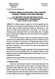
The TDU brings together all the components necessary for a FSPS for test which include radiator panels, Stirling power converters, core, pump, volume accumulator, as well as data acquisition and control systems. The responsibility for delivery of the components is divided between the national laboratories and NASA centers. The RxSim was originally designed to be a stand-alone system based on a two loop design that contained a core, a pump, a liquid-to-liquid heat exchanger that transferred the heat to a second loop that contained a pump, and a pair of Stirling engines. Separation would have been made at the intermediate side of the heat exchanger allowing for the RxSim to be 'plug and play' when installed into the TDU. However, in August of 2010 budget shortfalls required the TDU design to change to a single loop design by removing the heat exchanger and intermediate loop components, thus reducing the system to one loop. This single loop will need to be disassembled and re-assembled when delivered to GRC in March 2012. FIGURE 1 shows a rendering of the 2-Loop TDU design layout installed in Tank 6 at GRC, a 25 foot diameter by 68 foot long vacuum chamber; the 1-Loop design is similar in scale. A positive benefit to this change is greater design flexibility and less coordination required between MSFC and GRC on integration issues.
FIGURE 1. TDU Conceptual Layout.
REACTOR SIMULATOR The RxSim is an amalgam of mechanical components, the data acquisition system, and the control software used to monitor and control all operations of the RxSim. By building and testing the RxSim prior to delivery at GRC most of the bugs can be worked out, eliminating this burden from integration into the TDU and allowing the system to be characterized and the control codes adjusted to perform as needed. The mechanical configurations is discussed in the following sections.
Component Layout The component layout for the RxSim considers many factors. First, the RxSim must fit within the test chamber. At MSFC this test chamber is a 3.05 m (10 ft) diameter by 6.10 m (20 ft) long vacuum chamber. FIGURE 2 shows a transparent view of the vacuum chamber. Component relative positions are considered to facilitate gravity draining of NaK; if pockets of NaK are left in the test article this can present a problem during operation, fill, and drain. This configuration is not prototypic of an actual FSP reactor system with respect to component placement. With the component positions determined, support structures and spill containment are designed. A great deal of coordination
Proceedings of Nuclear and Emerging Technologies for Space 2011 Albuquerque, NM, February 7-10, 2011 Paper 3508
and planning between GRC and MSFC for the structural integration is needed to ensure quality integration and a final product that will be perform as planned. A Department of Energy (DOE) facility, Oak Ridge National Laboratory, leads the data acquisition and control integration effort, providing the continuity of systems and information between GRC and MSFC.
FIGURE 2. Component Identification on the Redesigned RxSim Single Loop Design.
Core The test core was designed by MSFC based upon the FSPS nuclear core designed by Los Alamos National Laboratory.2 The nuclear design of the core is a 37 pin UO2 fueled fast spectrum, pumped liquid-metal NaK cooled reactor with Stirling based power conversion. The physical geometry of the RxSim core was taken from the nuclear design, preserving the critical elements such as pin spacing and size. Some core design requirements and the as-built capability are presented in TABLE 1.
TABLE 1. Core requirements and as-built capability. Parameter Nominal/Transient Power Pins Control Zones Outlet/Peak outlet Tin/Tout Delta Maximum Press Drop at 1.75kg/s flow Thermocouples
Requirement 55/90 37 12 875/925 50 14
As-Built 55/+100 36 (Center pin for TC's) 12 875/925 200