May 3, 2010 - Outline. Variable Stiffness Joint Design. VSJ Implementation. VSJ Based on Compliant Flexures. VSJ Robot Control. Robot Dynamic Model.
Design and Control of Variable Stiffness Actuation Systems Gianluca Palli, Claudio Melchiorri, Giovanni Berselli and Gabriele Vassura DEIS - DIEM - Universita` di Bologna LAR - Laboratory of Automation and Robotics Viale Risorgimento 2, 40136, Bologna
May 3, 2010
Gianluca Palli (Universita` di Bologna)
VIA Workshop @ ICRA 2010
May 3, 2010
1 / 20
Outline
Variable Stiffness Joint Design VSJ Implementation VSJ Based on Compliant Flexures VSJ Robot Control Robot Dynamic Model Static Feedback Linearization Sliding Mode Controller Output-based Controller Conclusions
Gianluca Palli (Universita` di Bologna)
VIA Workshop @ ICRA 2010
May 3, 2010
2 / 20
Variable Stiffness Joint Design
VSJ Implementation
Characteristics of VSJ Drawbacks of the Variable Stiffness Actuation: ◮ ◮ ◮ ◮
A more complex mechanical design The number of actuators increases Non-linear transmission elements must be used High non-linear and cross coupled dynamic model
Design Approach
Open design issues: ◮
Mechanical implementation
◮
Physical dimensions Stiffness range
◮ ◮ ◮
Displacement range Torque/Displacement relation
Gianluca Palli (Universita` di Bologna)
VIA Workshop @ ICRA 2010
◮
The joint structure and dimensions have been fixed
◮
A compliant transmission element has been designed to achieve the desired joint behavior May 3, 2010
3 / 20
Variable Stiffness Joint Design
VSJ Implementation
Joint Frame Structure ◮
Antagonistic configuration τ{1,2}
= K (ǫ{1,2} )
ǫ{1,2} τJ
= θ{1,2} ± θJ = τ1 − τ2
SJ
=
∂K (ǫ1 ) ∂K (ǫ2 ) − ∂θJ ∂θJ
τe θj Motor 2
θ2
θ1 τ2
◮
◮
Compact and simple joint frame design The compliant element is changeable
Gianluca Palli (Universita` di Bologna)
VIA Workshop @ ICRA 2010
Motor 1
τ1
Nonlinear Nonlinear Elastic Elastic Moving Link Transmission Transmission (CTE) (CTE)
May 3, 2010
4 / 20
Variable Stiffness Joint Design
VSJ Implementation
Joint Frame Structure ◮
τ{1,2}
= K (ǫ{1,2} )
ǫ{1,2} τJ
= θ{1,2} ± θJ = τ1 − τ2
SJ
◮
◮
Moving Link
Antagonistic configuration
=
Nonlinear Elastic Transmission (CTE)
Nonlinear Elastic Transmission (CTE)
∂K (ǫ1 ) ∂K (ǫ2 ) − ∂θJ ∂θJ
Compact and simple joint frame design The compliant element is changeable
Base Link (Common Frame)
Motor 2 Gianluca Palli (Universita` di Bologna)
VIA Workshop @ ICRA 2010
Motor 1 May 3, 2010
4 / 20
Variable Stiffness Joint Design
VSJ Implementation
Joint Frame Structure ◮
Antagonistic configuration τ{1,2}
= K (ǫ{1,2} )
ǫ{1,2} τJ
= θ{1,2} ± θJ = τ1 − τ2
SJ
◮
◮
=
Moving Link
Main Shaft
CTE Shaft Gear
Shaft Gear & CTE Support + Bearings
∂K (ǫ1 ) ∂K (ǫ2 ) − ∂θJ ∂θJ Joint Encoder
Compact and simple joint frame design The compliant element is changeable
Base Link Motor Gear
Shaft Support + Bearing
DC Motors Motor Encoders
Gianluca Palli (Universita` di Bologna)
VIA Workshop @ ICRA 2010
May 3, 2010
4 / 20
Variable Stiffness Joint Design
VSJ Implementation
Design Considerations The selection of suitable displacement and stiffness ranges depend on: ◮ ◮ ◮ ◮
the inertia of the robot the robot cover (soft cover) the maximum velocity and load the adopted security criteria
Does an optimal torque/displacement (stiffness) relation exists? ◮ Several different torque/displacement characteristic can be found in current VSJ implementations ◮ ◮ ◮ ◮
◮
Quadratic Polynomial Exponential ...
Quadratic torque/displacement relation presents some interesting advantages from the control point of view
Gianluca Palli (Universita` di Bologna)
VIA Workshop @ ICRA 2010
May 3, 2010
5 / 20
Variable Stiffness Joint Design
VSJ Implementation
Selection of the torque/displacement relation τe
◮
◮
Quadratic stiffness relation of the coupling elements allows constant stiffness along joint displacement Actuators and Joint Torques τ{1,2} τJ
◮
θj Motor 2
θ2
θ1 τ2
Motor 1
τ1
Nonlinear Nonlinear Elastic Elastic Moving Link Transmission Transmission (CTE) (CTE)
= α2 ǫ2{1,2} + α1 ǫ{1,2} + α0 = [α2 (θ1 + θ2 ) + α1 ][θ1 − θ2 + 2θJ ]
Joint Stiffness SJ = 2 [α2 (θ1 + θ2 ) + α1 ]
Gianluca Palli (Universita` di Bologna)
VIA Workshop @ ICRA 2010
May 3, 2010
6 / 20
Variable Stiffness Joint Design
VSJ Based on Compliant Flexures
Introducing Compliant Flexures ◮
Exploit compliant flexures enhances the compactness and the flexibility of the design ◮ ◮
◮
Concentrated deformation and with linear elastic deflection Continuous compliant mechanisms
Nonlinear torsional stiffness has been achieved by using compliant elements with linear elastic deflection (Palli et al., IDETC 2010 [PBMV10]) Ψ1
Outer Frame
Inner Frame k3 k2
r3
r2
r4
γ2
k3
Coupler
γ3 Crank
k2
γ3
k4
r4
φ
γ4
δ
r2 r1
Rocker
r3
γ2 r1
λ
k4
Inner Frame Outer Frame
Gianluca Palli (Universita` di Bologna)
γ4
β
VIA Workshop @ ICRA 2010
Base
May 3, 2010
7 / 20
Variable Stiffness Joint Design
VSJ Based on Compliant Flexures
Compliant Elements Design Procedure ◮ ◮
Selection of the material Optimization of the compliant elements design ◮ ◮ ◮
to obtain a quadratic torque/displacement relation with the desired displacement given the stiffness range 25 Optimized Desired FEM Analysis
Reaction Torque T1 [N m]
20
15
10
5
0
−5
−10 −0.5
−0.4
−0.3
−0.2
−0.1
0
0.1
0.2
0.3
0.4
0.5
Deflection Ψ1 [rad]
Gianluca Palli (Universita` di Bologna)
VIA Workshop @ ICRA 2010
May 3, 2010
8 / 20
Variable Stiffness Joint Design
VSJ Based on Compliant Flexures
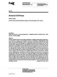
VSJ Prototype ◮
Prototype of the VSJ with compliant flexures
Gianluca Palli (Universita` di Bologna)
VIA Workshop @ ICRA 2010
May 3, 2010
9 / 20
Variable Stiffness Joint Design
VSJ Based on Compliant Flexures
VSJ Prototype ◮
Prototype of the VSJ with compliant flexures
Gianluca Palli (Universita` di Bologna)
VIA Workshop @ ICRA 2010
May 3, 2010
9 / 20
Variable Stiffness Joint Design
VSJ Based on Compliant Flexures
VSJ Prototype ◮
Prototype of the VSJ with compliant flexures 30
Effective Desired 20
Stiffness [N m rad−1 ]
Joint Torque [N m]
10
94.4 83.0 71.5 60.0 48.5 37.0 25.5
0
−10
−20
−30 −0.4
−0.3
−0.2
−0.1
0
0.1
0.2
0.3
0.4
Joint Deflection [rad]
Gianluca Palli (Universita` di Bologna)
VIA Workshop @ ICRA 2010
May 3, 2010
9 / 20
VSJ Robot Control
Robot Dynamic Model
Dynamic Model of Robots with Variable Joint Stiffness ◮
Dynamic equations of a robotic manipulators with elastic joints ˙ + K (q − θ) M(q) q¨ + N(q, q) B θ¨ + K (θ − q)
◮
The diagonal joint stiffness matrix K = diag{k1 , . . . , kn },
◮
= 0 = τ
K = K (t) > 0
The dynamics of the joint stiffness k is written as a generic nonlinear function of the system configuration (Palli et al., ICRA 2007 [PMW+ 07]) k¨ = β(q, θ) + γ(q, θ) τk ◮ ◮
The stiffness depends on the joint and actuators relative positions The dynamics of some mechanism used to adjust the stiffness is considered
Gianluca Palli (Universita` di Bologna)
VIA Workshop @ ICRA 2010
May 3, 2010
10 / 20
VSJ Robot Control
Robot Dynamic Model
Dynamic Model of Robots with Variable Joint Stiffness ◮
Dynamic equations of a robotic manipulators with elastic joints ˙ + K (q − θ) M(q) q¨ + N(q, q) B θ¨ + K (θ − q)
◮
The diagonal joint stiffness matrix is considered time-variant K = diag{k1 , . . . , kn },
◮
= 0 = τ
K = K (t) > 0
The dynamics of the joint stiffness k is written as a generic nonlinear function of the system configuration (Palli et al., ICRA 2007 [PMW+ 07]) k¨ = β(q, θ) + γ(q, θ) τk ◮ ◮
The stiffness depends on the joint and actuators relative positions The dynamics of some mechanism used to adjust the stiffness is considered
Gianluca Palli (Universita` di Bologna)
VIA Workshop @ ICRA 2010
May 3, 2010
10 / 20
VSJ Robot Control
Robot Dynamic Model
Dynamic Model of Robots with Variable Joint Stiffness ◮
Complete robot dynamics with uncertainties ˙ + K (q − θ) + ηq (t) M(q) q¨ + N(q, q) B θ¨ + K (θ − q) + ηθ (t) h i γ(q, θ)−1 k¨ − β(q, θ)(t) + ηk (t) ◮
◮
◮
= 0 = τ = τk
All the effects due to frictions, dead-zones, non-modeled dynamics, parameters variability etc., can be introduced by the additive functions η{q,θ,k } (t) In the nominal case → η{q,θ,k } (t) = 0
The input u and the robot state x are: � � � τ , x = q T q˙ T θT θ˙T u= τk
Gianluca Palli (Universita` di Bologna)
VIA Workshop @ ICRA 2010
kT
k˙ T
�T
,
y=
�
q k
�
May 3, 2010
11 / 20
VSJ Robot Control
Static Feedback Linearization
Feedback Linearized Model ◮
The overall system can be written as � [4] � � � � � q α(x ) τ = + Q(x ) β(q, θ) τk k¨ where Q(x ) is the decoupling matrix: � −1 −1 M KB Q(x ) = 0n×n
◮
Non-Singularity Conditions ◮
→
M −1 Φ γ(q, θ) γ(q, θ) ki > 0 γi (qi , θi ) 6= 0
�
� ∀ i = 1, . . . , n
By applying the static state feedback �� � � � � � � τ α(x ) vq = Q −1 (x ) − + vk τk β(q, θ)
the linearized model is obtained (Palli et al., ICRA 2008 [PMD08]) � � [4] � � q vq = vk k¨ Gianluca Palli (Universita` di Bologna)
VIA Workshop @ ICRA 2010
May 3, 2010
12 / 20
VSJ Robot Control
Static Feedback Linearization
Feedback Linearized Model ◮
The overall system can be written as � [4] � � � � � q α(x ) τ = + Q(x ) β(q, θ) τk k¨ where Q(x ) is the decoupling matrix: � −1 −1 M KB Q(x ) = 0n×n
◮
Non-Singularity Conditions
M −1 Φ γ(q, θ) γ(q, θ)
Fully-decoupled linear model � represented kby>two 0 indipendent i ∀ i = 1, . . . , n → chains γof(q integrators , θ ) 6= 0 i
◮
�
i
i
By applying the static state feedback �� � � � � � � τ α(x ) vq = Q −1 (x ) − + vk τk β(q, θ)
the linearized model is obtained (Palli et al., ICRA 2008 [PMD08]) � � [4] � � q vq = vk k¨ Gianluca Palli (Universita` di Bologna)
VIA Workshop @ ICRA 2010
May 3, 2010
12 / 20
VSJ Robot Control
Sliding Mode Controller
Sliding Mode Controller ◮
The time-varying sliding surface is defined in the linearized state space: Z t [3] ¨q + Pq2 e˙ q + Pq1 eq + Pq0 eq dt eq + Pq3 e 0 Z S= t e˙ k + Pk 1 ek + Pk 0 ek dt 0
◮
If η{q,θ,k } (t) 6= 0: S˙ =
◮
�
[4]
eq ¨k e
�
+Pe =
"
[4]
qq k¨d
#
−
�
α′ (x , t) β ′ (q, θ, t)
�
− Q(x )
�
τ τk
�
+Pe
where α′ (x , t) and β ′ (q, θ, t) represent the dynamics of the system in the non-nominal case The actual control action is defined as (Palli & Melchiorri, ICAR 2009 [PM09]): � ′ � � � τ τ = + Q −1 (x )R sign(S) τk′ τk
Gianluca Palli (Universita` di Bologna)
VIA Workshop @ ICRA 2010
May 3, 2010
13 / 20
VSJ Robot Control
Sliding Mode Controller
Lyapunov Stability ◮
Candidate Lyapunov function: V =
◮
1 T S S 2
Condition for the asymptotic trajectory tracking: V˙ = S T S˙ = S T {F − R sign(S)} < 0 where F =
�
α(x ) β(q, θ)
�
−
�
α′ (x , t) β ′ (q, θ, t)
�
represents the residual dynamics of the manipulator due to non-prefect knowledge of its model and to spurious effects ◮
The elements of the matrix R must be larger than the error in the robot dynamics: Rii > |Fi |
◮
Given the boundedness of the the robot dynamics, a matrix R that globally satisfies the required conditions can be found
Gianluca Palli (Universita` di Bologna)
VIA Workshop @ ICRA 2010
May 3, 2010
14 / 20
VSJ Robot Control
Sliding Mode Controller
Simulation of a two-links Planar Manipulator ◮
Nominal Model + Exact Feedback linearization Joint positions [rad] 1 Pos Joint 1 Pos Joint 2
1
0
−1
−0.5
2
4
6
8
x 10
0.5
0
−2 0
Position errors [rad]
−5
2
10
Err Joint 1 Err Joint 2
−1 0
Joint Stiffness [N m rad −1 ]
2
1
3
6
8
10
Stiffness errors [N m rad −1 ]
−5
4
4
x 10
Err Joint 1 Err Joint 2
0.5
2 0 1
−1 0
−0.5
Stiff Joint 1 Stiff Joint 2
0 2
4
6
Time [s]
Gianluca Palli (Universita` di Bologna)
8
10
−1 0
VIA Workshop @ ICRA 2010
2
4
6
Time [s]
8
10 May 3, 2010
15 / 20
VSJ Robot Control
Sliding Mode Controller
Simulation of a two-links Planar Manipulator ◮
Perturbed Model + Simplified Feedback linearization Position errors [rad]
Joint positions [rad] 3
0.5 Pos Joint 1 Pos Joint 2
2
0
(b)
1
−0.5 0 −1
−1 −2 0
2
4
6
8
10
−1.5 0
Err Joint 1 Err Joint 2 2
4
6
8
10
Stiffness errors [N m rad −1 ]
Joint Stiffness [N m rad −1 ] 4
0.1
3
Err Joint 1 Err Joint 2
0.05
2 0 1
−1 0
−0.05
Stiff Joint 1 Stiff Joint 2
0 2
4
6
Time [s]
Gianluca Palli (Universita` di Bologna)
8
10
−0.1 0
VIA Workshop @ ICRA 2010
2
4
6
Time [s]
8
10 May 3, 2010
15 / 20
VSJ Robot Control
Sliding Mode Controller
Simulation of a two-links Planar Manipulator ◮
Perturbed Model + Simplified Feedback linearization + Sliding mode Joint positions [rad] 1 Pos Joint 1 Pos Joint 2
1
0
−1
−0.5
2
4
6
8
x 10
0.5
0
−2 0
Position errors [rad]
−5
2
10
Err Joint 1 Err Joint 2
−1 0
Joint Stiffness [N m rad −1 ]
2
2
3
6
8
10
Stiffness errors [N m rad −1 ]
−3
4
4
x 10
Err Joint 1 Err Joint 2
1
2 0 1
−1 0
−1
Stiff Joint 1 Stiff Joint 2
0 2
4
6
Time [s]
Gianluca Palli (Universita` di Bologna)
8
10
−2 0
VIA Workshop @ ICRA 2010
2
4
6
Time [s]
8
10 May 3, 2010
15 / 20
VSJ Robot Control
Output-based Controller
Output-based controller ◮
Both the robot, the motors and the stiffness dynamics are in the form: A(v , w)v¨ + f (v˙ , v , w) + α = τ
◮
By using the general output-based dynamic compensator: τ
◮
= A(v , w) τ¯ + f (z2 , v , w)
τ¯ z˙ 1
= −Λ1 (v − vd ) − Λ2 z2 + L(z3 − z2 ) = −Γ1 (z1 − v ) + z2
z˙ 2 z˙ 3
= −Γ2 (z1 − v ) + τ¯ − L(z3 − z2 ) = τ¯ − L(z3 − z2 )
the dynamics of these systems can be decoupled (Palli & Melchiorri, NOLCOS 2010 [PM10]) The controller provides direct estimations of the disturbance acting on the motors, on the stiffness and on the robot arm
Gianluca Palli (Universita` di Bologna)
VIA Workshop @ ICRA 2010
May 3, 2010
16 / 20
VSJ Robot Control
Output-based Controller
Simulation of a two-links Planar Manipulator ◮
Perturbed Model + Output-based controller End-effector positions [m]
Position errors [m]
−3
1
5
x 10
0.5 0 −0.5 −1 0
0 Pos x Pos y 2
Err x Err y 4
6
8
10
−5 0
2
4
6
8
10
Stiffness errors [N m rad−1 ]
Joint Stiffness [N m rad−1 ] 4
0.1
3
Err Stiff 1 Err Stiff 2
0.05
2 0 1
−1 0
−0.05
Stiff Joint 1 Stiff Joint 2
0 2
4
6
8
10
−0.1 0
Time [s] Gianluca Palli (Universita` di Bologna)
2
4
6
8
10
Time [s] VIA Workshop @ ICRA 2010
May 3, 2010
17 / 20
Conclusions
Conclusions ◮
◮
◮
◮
◮
A flexible and compact solution for the implementation of variable stiffness joints has been shown Complaint flexures have been adopted to improve compactness and to achieve the desired stiffness profile The model of a robotic manipulator with variable joint stiffness has been defined taking into account model uncertainties In the non-ideal case, the asymptotic tracking performance have been recovered by means of a sliding mode controller that compensates for model uncertainties A robust output-based controller for the indipendent control of the robot trajectory and joint stiffness has been shown
Questions? Thank you for your attention...
Gianluca Palli (Universita` di Bologna)
VIA Workshop @ ICRA 2010
May 3, 2010
18 / 20
Conclusions
Bibliography I G. Palli, G. Berselli, C. Melchiorri, and G. Vassura. Design and modeling of variable stiffness joints based on compliant flexures. In Proc. of the ASME 2010 Int. Design Engineering Technical Conf., Montreal, Canada, 2010. G. Palli and C. Melchiorri. Robust control of robots with variable joint stiffness. In Proc. Int. Conf. on Advanced Robotics, Munich, Germany, 2009. G. Palli and C. Melchiorri. Task space control of robots with variable stiffness actuation. In Proc. of the 8th IFAC Symp. on Nonlinear Control Systems, Bologna, Italy, 2010. G. Palli, C. Melchiorri, and A. De Luca. On the feedback linearization of robots with variable joint stiffness. In Proc. of the IEEE Int. Conf. on Robotics and Automation, 2008. Gianluca Palli (Universita` di Bologna)
VIA Workshop @ ICRA 2010
May 3, 2010
19 / 20
Conclusions
Bibliography II
¨ G. Palli, C. Melchiorri, T. Wimbock, M. Grebenstein, and G. Hirzinger. Feedback linearization and simultaneous stiffness-position control of robots with antagonistic actuated joints. In IEEE Int. Conf. on Robotics and Automation, 2007.
Gianluca Palli (Universita` di Bologna)
VIA Workshop @ ICRA 2010
May 3, 2010
20 / 20