Mar 18, 2017 - carburization and heat treatment, In a pneumatic rotary actuators widely use in valve operating as opening and closing system the rack and ...
IOSR Journal of Mechanical and Civil Engineering (IOSR-JMCE) e-ISSN: 2278-1684,p-ISSN: 2320-334X PP. 46-53 www.iosrjournals.org
Design and Development of Spur Pinion in Loading Condition with Different Material P.B.Vavhal1, K. C More2, A.A. Patil3 1
(Department of Mechanical Engineeringt, ALARD College of Engineering, India) (Department of Mechanical Engineering, MIT College of Engineering, Pune, India) 3 (Department of Mechanical Engineering, M.E.S.College of Engineering, S.P.Pune University, Pune, India) 2
Abstract: Gears are the very useful components in mechanical power transmission system and industrial rotating machinery, piping industry. A valve opening and closing application spur pinion generally subjected to two types of stresses like bending stresses and contact stresses which are causes teeth failure during meshing with another tooth. Gear design has been improved by using better material, hardening surfaces with carburization and heat treatment, In a pneumatic rotary actuators widely use in valve operating as opening and closing system the rack and pinion are use for valve operation in that failure in spur pinion observed for maximum pressure of 8 bar due to this failure causes actuators to be stop current operation this failure is high due to higher pressure load acting on pinion. This failure can be changed by assuming different material to existing design of spur pinion this modification minimizes failure in pinion and optimize the weight of application. Keywords: aluminum, spur pinion, steel, material, weight optimization.
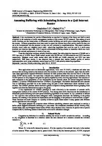
I. Introduction Gears are used for a variety of applications. They have numerous applications starting from textile looms to aviation industries. They are the most frequent ways of transmitting power. They will change the rate of rotation of machinery shaft as well as the axis of rotation. For high speed machine, such as an motor vehicle transmission, they are the optimum medium for low energy loss, high accuracy and reliability. Their function is to convert input provided simply by prime mover into an output with lower velocity and corresponding higher speed. Toothed gears are being used to transmit the power with high velocity ratio. In this phase, they face large stress at the point of contact. A set of teeth for is generally subjected to two types of cyclic stresses Bending stresses inducing bending fatigue and Contact stress causing contact fatigue.Both equally these kind of stresses may well not achieve their maximum values at the exact same point of contact. Nevertheless, combined action of that they are all is the reason of failure of gear tooth leading to fracture at the bottom layer of a tooth underneath bending fatigue and surface area failure, due to call fatigue. When loads will be applied to the body, their surfaces deform elastically near to the point of speak to. Stresses developed by Normal force in a photoelastic type of gear teeth are displayed in the Fig.1.1. The highest stresses can be found at the region where the lines are bunched nearest together. The greatest stress arises at two locations: A. At contact point exactly where the force F work. B. At the fillet region near to the base in the tooth.
Fig 1-Photoelastic Type Gear Teeth For application rotary actuator is an actuator that produces a rotary motion. The simplest actuator is purely mechanical, where linear motion in one direction gives rise to rotation. The most common actuators though are electrically powered. Other actuators may be powered by pneumatic or hydraulic power, or may use energy stored internally through springs. The motion produced by an actuator may be either continuous rotation, as for an electric motor, or movement to a fixed angular position as for servomotors and stepper motors. A further 6th National Conference RDME 2017, 17th- 18th March 2017. 46 | Page M.E.S. College of Engineering, Pune. 411001 DOI: 10.9790/1684-17010054653
Design and Development of Spur Pinion in Loading Condition With Different Material form, the torque motor, does not necessarily produce any rotation but merely generates a precise torque which then either causes rotation, or is balanced by some opposing torque.
Fig.2-Pnumatic Rotary Actuator In paper we mostly focus on only pinion but pneumatic rotary actuator having pneumatic rack and pinion actuators that can be used to control valves in pipeline transport. The actuators in the picture on the right are used to control the valves of large water pipeline. In the top actuator, a gray control signal line can be seen connecting to a solenoid valve (the small black box attached to the back of the top actuator), which is used as the pilot for the actuator. The solenoid valve controls the air pressure coming from the input air line (the small green tube). The output air from the solenoid valve is fed to the chamber in the middle of the actuator, increasing the pressure. The pressure in the actuator's chamber pushes the pistons away. While the pistons are moving apart from each other, the attached racks are also moved along the pistons in the opposite directions of the two racks. The two racks are meshed to a pinion at the direct opposite teeth of the pinion. When the two racks move, the pinion is turned, causing the attached main valve of the water pipe to turn.V.Rajaprabakaran, et.al. studied different shaped slot to reduce stress attention. A finite factor type of Spur gear with a segment of three teeth is known for evaluation and stress concentration minimizing holes of numerous sizes will be introduced on gear tooth at various locations. Evaluation revealed that aero-fin designed hole introduced along the stress flow direction produced better result.[1].Toni Jabbour, et.al. presented a method to calculate the distribution of the stress at the tooth origin along with the contact stress along each contact series of set of spur and helical gears. For the latter, the method is founded on the decomposition of the gear into an unlimited number of small field spur gears. The results received from this method include been further confirmed simply by finite factor calculations. To get spur gears, the location of the point of contact which causes to the critical tooth-root stress will depends on the contact ratio from the pair of gears which usually increases with the amount of teeth. The crucial contact stress is attanied at the radius from the pitch circle. For helical gears, the critical tooth-root stress is obtained in the event that the point of get in touch with situated at a range of 1.65 millimeter, while the contact stress is located at a radius equal to the radius of the pitch circle of the gear. Both stresses are obtained when the total length of lines of contact is minimal[2]. Vishwjeet V. Ambade, et.al. analysed of Bending stress and get in touch with stress of Involutes spur gear teeth in meshing. There are several verities of stresses present in loaded and rotating gear teeth. Bending stress and contact stress (Hertz stress) calculation is the simple stress analysis. It is usually difficult to get rigth answer on gear teeth stress by implying important stress equation, such while Lewis formula for bending stress and Hertz equation for contact stress. Numerous research methods just like Theoretical, Numerical and Experimental include been done throughout the years. This paper displays the theoretical and numerical method of to calculate bending and contact stress [3]. Mahesh. Badithe1, et.al. Static analysis of 3-D model got been performed by utilizing ANSYS 10.0. Analysis uncovered that aero-fin shaped gap introduced along the stress flow direction yielded better results. Finally Stress reducing feature using condition of shape of aero-fin can be used in the path of stress circulation which helped to regulate stress flow by redistributing the lines of force. This also yielded better results in comparison with elliptical and circular hole [4].
II. Problem Defination In this paper spur pinion are widely used for closing and opening valve. The failure are observed in pinion are due to various reasons like worst condition of loading, improper lubrication, corrosion etc. in the pinion failure generally start at root fillet radius .and the cracks may observed at fillets. This teeth failure may 6th National Conference RDME 2017, 17th- 18th March 2017. 47 | Page M.E.S. College of Engineering, Pune. 411001 DOI: 10.9790/1684-17010054653
Design and Development of Spur Pinion in Loading Condition With Different Material lead to failure in entire transmission system .this problem can be minimize by a selection of different material to a spur pinion. In the higher weight of part also lead problem in opening and closing pneumatic rotary actuators to such the weight reduction can be achieved by changing the material of spur pinion.One of the main causes for failure of the gear tooth is bending stresses near the root of the gear and the contact stresses where the gears meet. The main objective of this thesis is to analyze the bending stresses in the spur pinion. When the spur pinion mesh a tangential enervates stresses in the gear tooth. The radial load induces compressive stress of relatively small magnitude therefore its effect on the tooth may be neglected. The tangential load induces a bending stress which tends to break the tooth. Failure by bending will occur when the significant tooth stress equals or exceeds either the yield strength or the bending endurance strength of the material.
III. Objectives of Project In spite of the number of investigations devoted to gear research and analysis there still remains to be developed, a general numerical approach capable of predicting the effects of variations in gear geometry, bending stresses and Von-Mises stresses. The objectives of this thesis are to use a numerical approach to develop theoretical models of the behavior of gears in mesh, to help to predict the effect of gear tooth stresses and transmission error. The main focus of the current research as developed here is to analyses the failure of spur pinion. 1. Model of baseline of spur pinion by solid edge software. 2. Analyses the baseline spur pinion design by ansys and evaluate deflection and stress for different material as steel and aluminium. 3. Compare the defletion and stress for both. Fig. 3.1 shows the flowchart of methodology:
Fig 3.1-Flow Chart of Methodology
6th National Conference RDME 2017, 17th- 18th March 2017. M.E.S. College of Engineering, Pune. 411001
48 | Page DOI: 10.9790/1684-17010054653
Design and Development of Spur Pinion in Loading Condition With Different Material IV. Spur Pinion Design Calculation Table 1 shows input data for spur gear design. Table 2 shows the details of materials and Table 3 shows the data calculation sheet for spur gear. Table No 1- Input Data Type Rotary Pneumatic Actuator
Size in ( mm) 52
Pressure (Bar) P 8.0
Table No 2- Material Details Material Of Pinion Structural Steel Aluminum alloy
Min. Tensile Strength(Sut)Mpa 460 310
Min. Yield Strength(Syt)Mpa 250 280
Allowable Bending Stress (Sa= 0.66 * Syt )MPA 165 185
Table No 3- Data Calculation Sheet Sr No 1 2 3 4 5 6 7 8 9 10 11 12 13
Parameter
Symbol
Module Number Of Teeth Face Width Form Factor Pinion PCD Beam Strength Theo. Torque Transmitting Capacity Bore Diameter Pneumatic Pressure Perpendicular Distance Pneumatic Force Actual Torque To Be Transmitted Achieved factor of safety
m z b y d= m*z Fb= m*b*Sa*y T= Fb*(d/2)*2 D P d/2 F= (∏/4)*d^2*P Tact= F*(d/2)*2 FOS= T/Tact
CALCULATION Structural Steel Aluminium Alloy 1.25 mm 16 32 mm 0.304 20 mm 2006.4 N 2247.17 N 40.13 Nm 44.94 Nm 52 mm 8 bar 10 mm 1699.19 N 33.98 Nm 1.18 1.32
V. Cad Model Cad geometry was prepared as per machining conditions by using Solid Edge ST7.In that pinion cad drawing is below:
Fig. 4- Actual Model in Solid Edge ST7 5.1 Meshing A Tetrahedron Meshing is has 4 vertices, 6 edges, and is bounded by 4 triangular faces. in most cases a tetrahedral volume mesh can be generated automatically. A Pinion Tetrahedron Meshing Figure as Below:
Fig 5.1 - Meshing of Spur Pinion 6th National Conference RDME 2017, 17th- 18th March 2017. M.E.S. College of Engineering, Pune. 411001
49 | Page DOI: 10.9790/1684-17010054653
Design and Development of Spur Pinion in Loading Condition With Different Material 5.2 Loading and Boundary Conditions: Different sets (contact, fix, slave surface) were defined to apply boundary conditions. Boundary conditions applied for Spur Pinion Fix support applied on both sides of the gear as shown in the Figure Below:
Fig 5.2- Loading and Boundary Conditions 5.3 Post-Processing and Analysis: The post processing stage deals with the representation of results. Typically, the deformed configuration, mode shapes, temperature, and stress distribution are computed and displayed at this stage.For an example of a simple postprocessor; see the Java applet on these pages. Here you can, after analysis of a model, view the deformed model, and inspect stresses and displacements, both in the centroid of elements and the nodal values, and see contour plotting of these data. The analysis will deliver two different material pinion, in analysis we are focus on equivalent (von-Mises) stresses and deformation which will helpful for comparative study of the result. And the results obtained by FEA are as follows:
Steel Deflection:
Fig5.3-Steel Deflection Max. deflection of spur pinion= 0.014 mm
Aluminum Deflection
Fig5.4-Aluminium Deflection Max. deflection of pinion = 0.04 mm 6th National Conference RDME 2017, 17th- 18th March 2017. M.E.S. College of Engineering, Pune. 411001
50 | Page DOI: 10.9790/1684-17010054653
Design and Development of Spur Pinion in Loading Condition With Different Material 5.4 Equivalent (von-Mises) Stress both material: Following figure shows the bending stress.as here load is applied at tip of tooth maximum stress will be the tip as this . Steel Von-Mises Stress :
Fig. 5.5-Steel Material Von-Mises Result Total mass of the Gear = 181.32 gm Max. stress of gear = 103 MPa
Aluminium Von-Mises stress:
Fig.5.6-Aluminium Material Von-Mises Result Total mass of the Gear = 63.82 gm Max. stress of gear = 102 MPa 5.5 Equivalent strain both material: Steel Equivalent Elastic Strain:
Fig5.7-Steel Material Strain Result 6th National Conference RDME 2017, 17th- 18th March 2017. M.E.S. College of Engineering, Pune. 411001
51 | Page DOI: 10.9790/1684-17010054653
Design and Development of Spur Pinion in Loading Condition With Different Material
Aluminium equivalent elastic strain:
Fig.5.8-Aluminium Material Strain Result
VI. Results And Discussion Table 4-Results of FEA Details Deformation Von-Mises Stress Equivalent elastic strain Weight
Steel 0.014mm 103Mpa 0.00091 181.32gm
VII.
Aluminium 0.04mm 102 Mpa 0.0025 63.82gm
Conclusion
In this paper it is observed that the aluminum gear is most feasible than the steel in steel material spur pinion in a loading condition. In this analysis is to find out the total amount of stresses and deformation of gear tooth. Also observed by the help of ansys higher stress observed in steel is higher than the aluminum spur pinion. After comparing of behavior of gear set by considering steel and aluminium as gear material, aluminum provides reliability because of strength of in loading condition also.By analysis it can be found that no more stress changes for different material.fos of aluminum is greater than the steel material. Stresses occur is within safety limits. So aluminum is selected as the best material for less corrosion resistance, less weight and less cost than steel material.
References [1] [2] [3] [4] [5] [6] [7]
S. A. Badkas, N.Ajmera ,Static and Dynamic Analysis of Spur Gear, International Journal of Mechanical Engineering & Technology, 7(4), 2016, 8-21. Ghazi Asmar,Tooth stress calculation of metal spur and helical gears, Journal of Mechanism and Machine Theory, 92 ,2015, 375-390. Vishwjeet V.Ambade, A.V.Vanalkar, P.R.Gajbhiye,Involute Gear Tooth Contact And Bending Stress Analysis,International Journal of Computational Engineering Research, 3(8), 2013, 30-36. Mahesh. Badithe, Srimanthula Srikanth, Jithendra Bodapalli Stree and Reduction analysis of spur gear tooth, International Journal on Emerging Technology and Advanced Engineering, 4(4), 2014,760-767. J. Venkatesh, mr. P. B. G. S. N.Murthy ,design and structural analysis of high speed helical gear using ansys, International Journal of engineering research and applications. 4(3), 2014, 01-05. Kishor.N.naik, dananjay dolas ,Static analysis bending stress on gear tooth profile by variation of gear parameter with the help of FEA ,International Journal of Engineering Research and Technology, 3, 2014, 132-136 S.P.Shinde ,A.A. Nikam,T.S. Mullah,Static Analysis of Spur Gear Using Finite Element Analysis.,International Journal of Engineering Research and Technology, 4, 26-31.
6th National Conference RDME 2017, 17th- 18th March 2017. M.E.S. College of Engineering, Pune. 411001
52 | Page DOI: 10.9790/1684-17010054653