Software Component) framework and development envi- ronment. The DSC framework supports component ori- ented distributed communication architecture ...
Design and evaluation of the Distributed Software Component Framework for Distributed Communication Architectures John-Luc Bakker Harold J. Batteram Lucent Technologies, Bell Labs innovations @lucent.com Abstract We present our experiences with the DSC (Distributed Software Component) framework and development environment. The DSC framework supports component oriented distributed communication architecture such as TINA (Telecommunications Information Network Architecture). Within the component development environment, components can be developed and evaluated. Software components are self-contained packages of code that can be dynamically linked into a program. Operational interfaces cater for the external functionality of the component. The DSC can support both dynamic and static operational interfaces. Also, there can exist multiple instances of the same operational interface. Furthermore, components can be grouped together to form compound components. Through a common control and configuration interface the components can be configured with regard to events, properties, operational interfaces, life cycle, and composition. We apply this framework to a TINA based service and network architecture called MESH (Multimedia Services on the Electronic Super Highway). An example is provided; a shared white board service is created using the DSC framework. The shared white board service can be used in multimedia conferencing applications.
1. Introduction In this paper, we propose a DSC (Distributed Software Component) framework, which is a generalization and implementation of the TINA (Telecommunications Information Network Architecture) [14,15,16] computational object model. A DSC can be mapped to a computational object or computational object group. In the TINA computational model, computational objects1 are the fundamental architectural building blocks to construct TINA components. 1 Throughout this document the terms computational object and component are used interchangeable.
The TINA architecture is build along RM-ODP (Reference Model for Open Distributed Processing) [7] insights. RM-ODP suggests modeling a system from five different viewpoints: the business viewpoint, the information viewpoint, the computational viewpoint, the engineering viewpoint, and the technology viewpoint. The first viewpoint views a system from a high level and describes actors, roles, and responsibilities. The second viewpoint concentrates on information flows within the system. The computational viewpoint describes a system in terms of operations. The engineering model describes the implementation of the transparencies assumed by the computational model. Examples of such transparencies are location and concurrency transparencies. The last viewpoint, described by the technology model, views the system in terms of hardware and software constraints. The DSC framework supports concurrency and location transparencies. DSCs can be grouped to form compound components with arbitrary complex compositions of sub-components. In addition, the DSC framework addresses flexible configuration and dynamic component construction from (downloadable) sub-components. This shows that the DSC framework is an appropriate implementation of the TINA computational model. Component oriented programming (COP) is a recent trend in software engineering. COP has been described as a natural extension of object oriented programming to cater the needs of independently extensible systems [2,5,8,9]. COP allows developers to concentrate on highlevel application content, which improves the rate and productivity of development. Examples of this technology can be found in ActiveX™ components [1], OpenDoc [12], and JavaBean™ [10]. An important benefit of the component model is that it provides a higher level of abstraction compared to the object model and that it enables flexible software construction by combining and connecting individual components. The goal is to create a repository of multi-usable components that can be used for component-based software development. Software development then becomes the selection, adaptation, and composition of components rather than implementing the application from scratch.
Components hide their internal details behind a welldefined interface. By using OMG (Object Management Group) IDL (Interface Definition Language) [11,12] to specify and implement these interfaces, the component can be written in any language for which an OMG IDL mapping exists. Components share many characteristics with object orientation. However, the latter is more a programming discipline, which delivers its benefits to programmers directly, but only indirectly to end-users. For example, a C++ class library must be compiled into a program to use it. In contrast, a component is a self-contained package of code that can be dynamically linked into the system to extend its functionality. Section 1.1 further introduces TINA and Section 1.2 introduces MESH (Multimedia Services on the Electronic Super Highway). MESH is an implementation of the TINA architecture and it is build upon the DSC framework.
1.1 TINA TINA is an open architecture for the development, deployment, and operation of telecommunication systems. TINA is a component-oriented architecture and defines a set of service and network components, which interact through well-defined interfaces. TINA uses CORBA (Common Object Request Broker Architecture) [11,12] as a DPE (Distributed Processing Environment) [17] for inter-component communication. A TINA DPE must support location transparency. We expect TINA to play a major role in future telecommunication services, and we have decided to adopt the TINA architectural principles in the MESH project.
1.2 MESH The MESH project [13] aims at accelerating the introduction of advanced CSCW (Computer Supported Cooperative Work) services for the electronic super highway. It is carried out by a Dutch consortium consisting of Lucent Technologies, KPN Research, Telematics Institute, and several universities and research institutes. Besides validation of services developed in the Platinum project [3] in a number of pilots, it aims at the development and implementation of an open service and network architecture based on the results of TINA-C (Telecommunications Information Network Architecture Consortium). Within MESH, the TINA business, service, and computational models are adopted with minor modifications. TINA-C did not provide engineering and technology models. In the remainder of this paper, we will introduce the DSC framework, describe its common behavior and prop-
erties, and introduce the control and operational interfaces. In Section 3, we will present the DSC framework development environment. It consists of a skeleton generator, a script generator, and testing, monitoring, and debugging facilities. Section 4 describes a scenario of a simple shared white board service in which components are dynamically downloaded, configured, and collected into a compound component. In this section it is also shown how to specialize a component. We end this paper with conclusions and plans for future work.
2. The DSC framework The DSC framework defines the semantic rules and constraints, which allow the components to collaborate. Collaborating components perform a client and/or a server role; the client invokes an operation implemented through an interface on the server component. The interface(s) supported by a component are said to offer a service to a client component. Besides client initiated invocations the framework also supports event notification as an asynchronous communication publish/subscribe pattern.
2.1 Component internals DSCs share a number of features. Each component has a common control interface, the i_component interface, and zero or more operational interfaces. The i_component interface provides a standard interface for common services such as: • Property services, with operations to read and define them. • Component life cycle services, with operations such as create, delete, suspend and resume. • Transaction services, which allow the component to operate within the context of a transaction and with operations to commit or abort changes made. • Configuration services, which provide operations to support dynamic construction of compound components. • Debugging facilities, with which all invocations on an interface can be monitored. In addition, components share common behavior, for example the ability to be notified of or to subscribe to events. Each component has a standard property named EventList, which contains the list of events that can be generated by the component. A client can register with the component as observer for specified events. Clients can also list the events in which they show interest in their properties. The i_component interface is the root access point to the component. A client who wishes to use the services of another component must first obtain a reference to its
i_component interface. In the DSC framework clients may obtain i_component interface references through the CORBA naming service. Once the i_component
interface is obtained, operational interface references can be retrieved using the getOperational() operation. The operational interfaces provide the service specific operations implemented by a component. In the TINA computational object model a component may have several operational interfaces where each operational interface is a group of closely related operations. This allows different clients to have a different perspective of a component. For example, a component might support interfaces supporting management services and interfaces supporting control services. Legend
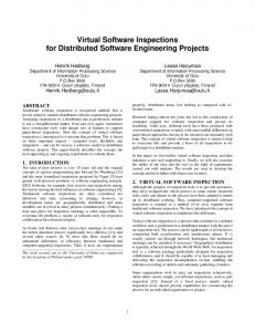
level. Figure 2 shows an example of compound component containing two components. One of both is also the control component. Legend
Control component
Interface visible for compound component peers.
Contained component Invocation Compound component
Figure 2. Compound component.
Container I.O. Implementation object
Core of distributed software component Control interface (i_component) Operational interface (i_operational)
Figure 1. DSC. Figure 1 depicts a DSC including the obligatory control interface and one operational interface. The component exists within a container. A container can be compared with a process. It models the frameworks unit of failure.
2.2 Compound components A compound component is a (possibly recursive) aggregate of sub-components, which, from an external view, is similar to single component, i.e. presenting the same set of operational interfaces, properties etc. One of the main strengths of the DSC framework is the ability to dynamically create such compound components. This feature allows the dynamic construction of complex components from simpler ones and stimulates the reuse of basic building blocks. Compound components present a single i_component interface and a single identity to the external world. The i_component interface is provided by a control component. A control component may be an additional component, or a sub-component, assigned this role. Client components obtain operational interface references for any of the sub-components through the i_component interface of the control component. The control component also defines which properties, interfaces, or events from subcomponents are exported and visible at the compound
Compound components are dynamically created through operations provided by the i_component interface of a control component. These operations are (in OMG IDL notation): void addComponent( in i_Component c ); void removeComponent( in i_Component c ); void exportOperational( in i_Component c, in string type );
A control component maintains a list of subcomponents. The operation addComponent will add the given sub-component reference to this list. The operation exportOperational will add the given interface to a list of externally visible interfaces, which is also maintained by the control component. Both these lists are available as properties and can be queried by other components.
2.3 Component properties In general a property is an attribute of a component or interface which can be used to provide detailed information about the component. A property has a name, type and value. Within the DSC framework properties can be manipulated within the operational interface that contains the property or within the control interface of the component, if the property is contained in the component. Properties can be used as configuration variables, for example to specify engineering attributes such as concurrency policies, interface names, event generation, component composition etc.
2.4 Configuration of components Ideally, a component can just be plugged into an application and reused as is. However, this view is unrealistic. In practice a component has to be adapted in some way to match the requirements for the particular application and configuration in which the component is being used. Component designers need to anticipate for a range of possible configurations and provide configuration options for a variety of situations. The distribution policy of component in containers is an example of a configuration issue. System designers, who construct systems by mixing and matching various components, need to specify the configurations for the components used. This configuration data may be written in some specification language, which can be interpreted by a universal “configurator” component. This component will read the configuration specification for a given component and configure the target component using its i_component interface. Based on the information in the configuration specification, the configurator can be used to create instances of sub-components, distribute them in containers, assemble compound components, and register components as observers for specific events. This scheme provides a highly flexible environment. The system can be changed (within the bounds and constraints of the configuration variables) by changing the various component configuration specification files.
3. Component development environment The component development tool set consists of a component specification language, a skeleton generator, a script generator, and testing, monitoring, and debugging facilities. Prior to developing the component specification language, we examined TINA ODL (Object Definition Language) [18]. TINA ODL is designed for the specification of TINA systems from the perspective of the TINA computational viewpoint. TINA ODL is an extension of OMG IDL; it additionally supports operational interfaces, stream interfaces, multiple interface objects, and object groups. Furthermore, the language allows to specify a quality of service per operation, it defines both interface and object inheritance, and it supports self-description. TINA ODL bridges the gap left by OMG IDL. With OMG IDL it is only possible to specify interfaces. Yet, OMG IDL does not allow to relate multiple interfaces with one implementation object, or to specify interfaces that are required by the current interface to execute its service. On the other hand, TINA ODL does not support events (otherwise than through asynchronous typed operations) and it does not support a special, obligatory
control interface. These requirements, and the fact there was no ODL compiler available, led to the conclusion that we had to develop a component specification language. The framework itself provides an OMG IDL file constituting a base component with i_component and i_operational interface specifications. Further, as we have decided to code the actual components in Java™ and OrbixWeb™ , an implementation of the base functionality is given in that programming environment. (A C++ and Orbix™ implementation is currently under development.) The component development environment enables to view the component from both a black box and a white box perspective. The black box perspective shields the developer from the internals, design structure, and programming language of a component. Only the OMG IDL defined interfaces and data structures are visible. Using only the black box perspective, components can be extended by encapsulating sub-components and exporting their interfaces. While still perfectly usable, the black box view supports reuse only at the component level and does not utilize reuse within the components at an object level. The white box perspective reveals much more detail about the component internal structure and has more potential for reuse at a finer granularity level. At object level, the developer is not aware of the distributed environment in which the component will be executed; all the interactions with the CORBA implementation are handled by the generated code. This relieves the need for ‘expert’ programmers. Additionally, the generated Java™ code adheres to the JavaBean™ coding rules [10]. For example, a black box event specified in OMG IDL is mapped on a white box JavaBean™ event. Source adhering to the JavaBean™ coding rules is suited for visual composition (see, for example, the BeanBox™ [10]). The remaining discusses the component specification language in more detail and the various tools that make up the component development environment are introduced.
3.1 Component specification language The component specification language specifies a component. It can specify static compound components and list per sub-component which of its interfaces is to be supported be the compound component. Per component it lists emitted and accepted notifications, supported and required interfaces, and component properties. Also, it lists per interface emitted and accepted notifications, and interface specific properties. Supported interfaces can be specified to be dynamic or static. Note that interfaces are not specified in the component specification language; they are specified in OMG IDL. Lastly, events can be named and typed; the event types are compatible with OMG IDL.
The following code exemplifies the usage of the component specification language. It specifies a component named myComponent supporting the i_interface operational interface and requirering the i_required operational interface. The component can fire and accept one event. It does not specify any properties. component myComponent { interface i_interface {} requires { i_required } accepts acceptedEvent as string fires firedEvent as octet }
3.2 Component development tools Figure 3 shows the component development process. During component development three separate stages can be identified: specification of interfaces and events in OMG IDL, specification of components in the component specification language, and implementing the components behavior in any language for which there exists IDL bindings. We used Java™ as an implementation language. IDL files
Developer modifies
Component spec. file
4. Example
Skeleton Generation Component Skeleton files
Compiler
Component jar files
of implementation skeleton files. The generated Java™ files contain code to start the static interfaces, to encapsulate components, export static interfaces, and to set the specified properties. Also, implementation skeletons, code needed to map events to JavaBean™ events, and intermediate debug source is generated per interface. All generated and modified files are compiled using a Java™ compiler and the resulting classes are collected in a JAR (Java™ Archive) file. A generated JAR file contains all required classes and resources needed at run-time. Furthermore, some scripts are generated to relieve the burden of managing the classpath environment variable and to ensure that eventually all Java™ class files are packed into the JAR file. The last stage consists of implementing and testing the behavior of the components. Except for the previously generated scripts, implementation skeletons, and debugging facilities, this stage is not further automated. The debugging facilities can be optionally activated per interface. They can be used to gradually monitor all invocations on an interface or to trace a sequence of invocations on subsequent interfaces. The later information can be graphically presented. It is especially useful to verify the dynamic behavior of the components with the message sequence diagrams found in the design documents.
Component repository
Figure 3. Component development process. During the first stage all required and supported (both static and dynamic) interfaces and all emitted and accepted event types are specified in OMG IDL. During the second stage the component specification language is used. Basically, it relates interfaces and event types together to form a component. In addition, information about component composition, interfaces imported from sub-components, properties, incoming and outgoing event can be specified. A component skeleton generation tool is developed which processes OMG IDL files together with component specification files to generate a set
Here we exemplify a shared white board service. It features dynamic download-able components, component configuration, and dynamic compound component creation within a distributed communication architecture. The distributed communication architecture is an implementation the TINA service architecture [16]. For simplicity, the example will not discuss modification of the service session. Also, we also did not include TINA network components dealing with streams since our implementation of the shared white board does not use streams. For implementing the TINA shared white board service we used the following generic service architecture components: SS-UAP (Service Session User Application), USM (User Session Manager), and SSM (Service Session Manager). The generic SS-UAP manages the service session in the user domain for example, it keeps track of the windows on the screen associated with the service. The USM manages the user specific data within the service provider domain for example; it keeps track of SS-UAP interface references. Finally, the SSM manages the service session. Figure 4 shows some generic components during a three party session between a service provider domain and customer domains A, B, and C.
A service specific SSM is composed in a similar way.
4.1 Specializing a component Prior to initiating a TINA service a customer has initiate an access session with a service provider. During the access session other customers are invited to join the service. The access session will initiate a service session and instantiate three USM components, a service specific SSM, and request instantiation of service specific SSUAPs in the customer domains. SS-UAP
USM
Customer A SS-UAP
USM
SSM
Customer B SS-UAP Customer C
USM
4.2 Dynamic downloading a component It is assumed that a customer of a TINA network has a generic SS-UAP in its component repository. On the other hand, it can not be assumed that the customer possesses all or even the latest service specific SS-UAPs. This is not necessary, since the distributed component framework supports dynamic downloading of components. Dynamic downloading of components occurs only if the framework fails to instantiate a component. This typically happens if the component is not found in the component repository. The framework will then contact known component repositories and start downloading the requested component. After downloading the framework will continue executing as if the component was found in the repository in the first place.
4.3 Composing a compound component Service provider
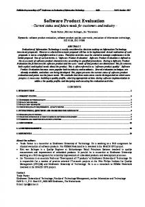
Figure 4. Generic TINA service architecture components collaborating in a three-party session. A shared white board service specific SS-UAP is modeled in Figure 5 and its component specification code follows. It is a compound component containing the obligatory control component, the generic SS-UAP, and a shared white board component containing the shared white board service specific behavior. The shared white board component shown supports and exports two operational interfaces. A shared white board service specific operational interface and the generic SS-UAP’s operational interface. The later is only supported; its behavior is delegated to the generic SS-UAP. Hence, the figure illustrates how to specialize a generic SS-UAP. component c_SWB_SS_UAP { contains { c_SWB _Control, c_SS_UAP, c_SWB } interface i_SWB {} interface i_SS_UAP_USM {} } component c_SWB_Control {} component c_SS_UAP { interface i_SS_UAP_USM {} } component c_SWB { interface i_SWB {} interface i_SS_UAP_USM {} }
Figure 5 shows a possibly dynamic downloaded control component of the service specific SS-UAP. A control component allows to dynamically configure and compose the compound component (see Section 2.2). In fact, the compound component shown in the figure is a specialization of the generic SS-UAP; it still supports the operational interface supported by the generic SS-UAP, but it additionally supports an operational interface offering the shared white board service.
service specific SS-UAP
generic SS-UAP
control component
white board component
Customer
Figure 5. Compound component encapsulating the generic SS-UAP and a shared white board component.
5. Conclusions and future work We have introduced and implemented the DSC framework, which supports a component oriented view of system design. It can be used to implement a TINA computational object or computational object group. The DSC
framework provides a common collaboration model supporting distribution transparency. The single control interface hides the internal composition and provides a standard common access point to properties, events, and supported operational interfaces. The ability to encapsulate components within compound components provides specialization of components through composition. Component composition can even be done at run-time. Components provide a high abstraction level, allowing system architects to concentrate on system level aspects rather than be concerned with low-level details. We have shown that such a framework provides a powerful technique to create distributed communications architectures. For the future we intend to continue our work on the component specification language. If components are designed to be reused and manipulated in graphical development environments, it is obligatory that the components, events, and its interfaces are self-documenting. Hence, the language should support such features. For seamlessly supporting reuse of components we have to work on a universal configuration language and a corresponding configurator component.
References [1] ActiveX, see http://www.microsoft.com/ [2] H.J. Batteram and H.P. Idzenga, “A Generic Software Component Framework for Distributed Communication Architectures,” ECSCW’97 Workshop on Object Oriented Groupware Platforms, 1997, Lancaster UK, pp. 68-73. [3] F.V. Baumann and H. Ouibrahim, “A network based approach for distributed multimedia applications,” ISS’97: World Telecommunications Congress, Toronto Canada, September 1997. [4] J.A. van den Broecke and J.O. Coplien, “Using Design Patterns to Build a Framework for Multimedia Networking,” Bell Labs Technical Journal, 2(1), Lucent Technologies, Murray Hill (NJ) USA, Winter 1997, p. 166187.
[5] CORBA Component Model RFP, see http://www.omg.org/library/schedule/ CORBA_Component_Model_RFP.htm [6] Gamma, E., R. Helm, R.E. Johnson, and J. Vlissides; Design Patterns - Elements of Reusable Object-Oriented Software, Addison-Wesley, New York (NY) USA, 1995. [7] International Stardards Orgainzation, Basic reference model of Open Distributed Processing - Part 1: Overview and guide to use, Standard ISO.IEC 10746-1, 1995. [8] International Workshop on Component-Oriented Programming; Jyväskylä Finland, 1997, see http://www.ide.hkr.se/~bosch/WCOP97/pape rs.html [9] International Workshop on Component-Oriented Programming; University of Linz, Linz Austria; 1996, see http://www.ide.hkr.se/~bosch/WCOP97/WCOP .96.report.ps [10] JAVA Beans, see http://java.sun.com/ [11] OMG/CORBA, see http://www.omg.org/ [12] Orfali, R., D. Harkey, and J. Edwards, The essential distributed objects survival guide, Wiley, New York (NY) USA, 1996. [13] M. van Sinderen and L. Ferreira Pires, “The application of TINA in multimedia services for the electronic super highway,” IDMS’98 Workshop on Interactive Distributed Multimedia Systems and Telecommunication Services, Oslo Norway, September 1998. [14] TINA-C, Network Components Specification, Hamada, T., and F. Steegmans (ed.), TINA-C, Redbank (NJ) USA, December 1997. [15] TINA-C, Network Resource Architecture, Steegmans, F. (ed.), TINA-C, Redbank (NJ) USA, February 1997. [16] TINA-C, Service Architecture, Kristiansen, L. (ed.), TINAC, Redbank (NJ) USA, June 1997. [17] TINA-C, TINA DPE Architecture, Gavras, A., and W. Takita (ed.), TINA-C, Redbank (NJ) USA, November 1997. [18] TINA-C, TINA Object Definition Language Manual, Parhar, A. (ed.), TINA-C, Redbank (NJ) USA, July 1996.