Tue-Af-Po2.07-27
1
Design and Experimental Tests of a Superconducting Hybrid DC Circuit Breaker X. Pei, O. Cwikowski, A. C. Smith, Senior Member, IEEE, and M. Barnes, Senior Member, IEEE
Abstract— Direct current (DC) circuit breakers are a key enabling technology for fault management in multi-terminal high voltage direct current (HVDC) systems. DC fault isolation is challenging due to the high rate of rise of the fault current and the lack of natural current zero-crossings found in AC systems. In this paper we present a novel superconducting hybrid DC circuit breaker which utilizes the intrinsic characteristics of the superconductor material. The automatic quench of the superconductor coil as a result of a high fault current transfers the current from the mechanical switch to the semiconductor switch. The isolating mechanical switch is able therefore to open at low current and recover its dielectric capability rapidly. A low voltage DC circuit breaker prototype has been built using a multi-strand Magnesium Diboride (MgB2) coil, a vacuum interrupter and an IGBT module. This prototype successfully demonstrated interruption of 500 A DC within 4.4 ms. This paper includes the design of the superconducting hybrid breaker prototype and a detailed analysis of the experimental results. This superconducting hybrid DC circuit breaker has significant potential for scaling-up to high voltage and high current applications. Index Terms— DC circuit breaker, hybrid circuit breaker, Magnesium Diboride, MgB2, mechanical switch, semiconductor switch, and superconducting coil.
I. INTRODUCTION igh voltage direct current transmission systems supplied by voltage-source converters (VSC-HVDC) offer significant advantages over high voltage alternating current (HVAC) systems for long distance high power delivery [1]. VSCHVDC enables independent control of active and reactive power, which is particular beneficial for offshore wind farm connections to onshore AC grids [1]. For example, the North Seas Offshore Grid has been proposed to integrate offshore wind farms and other renewable energy across the northern seas of Europe using a meshed HVDC grid [2, 3]. However, DC fault isolation is much more challenging than for AC systems because of the much higher rate of rise of the fault current in the DC system and also there is no natural zerocrossing of the current to aid fault isolation. Fast operating DC circuit breakers therefore are acritical technology for manag-
H
This work was funded as part of the UK EPSRC, FCL/CB: An Integrated VSC-HVDC Fault Current Limiter/Breaker project, EP/L021552/1. X. Pei is with the Department of Electronic and Electrical Engineering, The University of Bath, Bath, BA2 7AY, U.K. (e-mail:
[email protected]). O. Cwikowski is with National Grid, National Grid House, Warwick Technology Park, Gallows Hill, Warwick, CV34 6DA, U. K. A. C. Smith and M. Barnes are with the Power and Energy Division, School of Electrical and Electronic Engineering, The University of Manchester, Manchester, M13 9PL, U. K.
ing faults in DC grids. DC circuit breakers are required to detect and clear the fault within 2-5 milliseconds [4, 5]. A DC circuit breaker using a superconductor for current limiting has been proposed and experimently investigated [6, 7]. Superconductor materials are ideal for DC networks since they do not introduce AC losses when operating with pure DC current, and naturally transition to a high resistance very rapidly when exposed to an overcurrent. This paper presents a novel superconducting hybrid DC circuit breaker, which has the potential to offer low operating losses and fast operation [8]. The superconductor coil is only expected to limit the fault current for several milliseconds when integrated into the hybrid DC circuit breaker, which significantly reduces the possibility of the superconductor coil overheating and also reduces the volume of superconducting material required. This superconducting hybrid DC circuit breaker comprises a superconducting coil, a mechanical switch, one (or more) semiconductor(s) and varistor(s). NASA recently patented a hybrid DC circuit breaker, which is similar to this concept, except that cryogenic contacts were used for the mechanical switch [9]. This paper discusses the operation and design of the superconducting hybrid DC circuit breaker, detailing the construction of a low voltage prototype breaker. The superconducting coil used was a multi-strand Magnesium Diboride (MgB2) manufactured by Hyper Tech Research Inc. A vacuum interrupter and an Insulated Gate Bi-polar Transistor (IGBT) were also utilized to form the hybrid circuit breaker prototype.
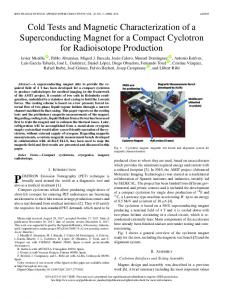
II. STRUCTURE OF SUPERCONDUCTING DC CIRCUIT BREAKER A schematic diagram of the superconducting hybrid DC circuit breaker and its test circuit is shown in Fig. 1. This superconducting hybrid DC circuit breaker shown in the dashed box has three parallel branches: the primary branch consists of a superconducting coil Rsc in series with a mechanical switch M1; the secondary branch is made from a semiconductor switch S1; and the third branch consists of a varistor V1 [8]. A residual breaker M2 is placed in series with all these three parallel branches to provide full isolation. In this design the superconducting coil is used as a commutating element, which diverts the current from the mechanical switch to the semiconductor branch during a fault condition. The operating principle of this hybrid DC circuit breaker is explained as follows. During normal operation, the current
Template version 8.0, 27 July 2017. IEEE will put copyright information in this area See http://www.ieee.org/publications_standards/publications/rights/indes.html for more information.
2
flows through the superconductor and the mechanical switch which has a low resistance and hence low losses. The secondary semiconductor switch is normally kept open. When a fault occurs, the current rises rapidly until the quench current level of the superconductor is reached. The superconducting coil starts to quench and quickly develops resistance. The length of the superconducting coil is chosen so that adequate quench resistance is produced to limit the fault current effectively. The voltage appearing across the superconducting coil can be used as a fault trigger signal and the semiconductor switch is turned on after the superconductor quenches, providing a secondary path for the current to flow. The current starts to commutate from the primary branch to the secondary branch due to the increased resistance of the superconductor. The mechanical switch M1 can be opened when the current through it has reduced to a sufficiently low level. The semiconductor branch continues to conduct the fault current until the mechanical contacts are fully opened. The semiconductor branch can then be turned off once the mechanical switch recovers its voltage withstand level, The voltage across the circuit breaker increases rapidly to oppose the flow of the current. The residual energy is then dissipated in a varistor, which also limits the transient recovery voltage. The second mechanical switch M2 is used to break any residual current and provide full isolation. The speed and rating requirement of this second mechanical switch is much lower. Since the rate of rise of the fault current is usually very high in DC networks, fast operation means a lower fault current level for the DC circuit breaker to interrupt. One of the key advantages of this hybrid DC circuit breaker is that it provides automatic and fast operation so that the prospective DC fault current is lower compared with other types of DC circuit breakers.
voltage monitoring and the fault detection function will be added into the microcontroller control strategy in the near future. The design and selection of the superconducting coil is very similar to that used for a superconducting fault current limiter [10]. The length of the superconducting coil was approximately 6.28 m to provide the necessary voltage withstand and quench resistance. The diameter of the coil former was 200 mm and the coil had 10 turns. The superconducting coil was made from 9-strand monofilament MgB2 wire with a stainless steel sheath. The diameter of each individual wire was 0.36 mm and the fill factor of MgB2 was approximately 25%. The wire strands were twisted and transposed during the manufacture process to equalize the impedance of each parallel wire path. The MgB2 coil was made using a wind-and-react method: the coil was wound on a ceramic alumina former and then reacted at 700 °C for 30 mins [11]. The ceramic alumina former was chosen for the MgB2 coil due to its high thermal conductivity and its ability to withstand high temperatures during heat treatment and low temperatures during testing. Superconducting hybrid DC circuit breaker D1
I DC power supply
Im Rsc
M1
Is
S1
Iv
V1
M2
Rl
M3
Fig. 1. Schematic diagram of superconducting hybrid DC circuit breaker and its test circuit.
III. EXPERIMENTAL SETUP AND RESULTS A. Experimental setup A low voltage prototype of the superconductor hybrid DC circuit breaker prototype was built to verify the operating principle. The experimental test circuit and the prototype design is discussed in this section. The normal operating current and fault current is provided by a programmable DC power supply with voltage range of 0-52 V and current range of 0700 A. As shown in Fig. 1, the DC power supply is connected in series with a diode, a load resistor, a switch in parallel with the load resistor, and the circuit breaker prototype under test. The diode is used to block any reverse voltage once the DC circuit breaker interrupts the fault current and protect the DC power supply from any potential high voltage. The load resistance is 0.5 Ω in the test circuit. The switch in parallel with the load resistor can be controlled to short-circuit the load resistor, which creates the fault condition. The superconducting breaker prototype, shown in Fig. 2, comprises a superconducting coil, a vacuum interrupter and an IGBT. During the test, the operation of the mechanical switch and the semiconductor switch was controlled by a microcontroller based on a predefined operation sequence. Current and
Fig. 2. Superconducting hybrid DC circuit breaker prototype.
3
The superconducting coil was placed in a cryostat, which was filled with liquid nitrogen before testing. The temperature of the cryostat can be controlled from 20 K to 80 K using the Cryomech Gifford-McMahon (GM) cryofrigerator AL230 and the Lakeshore PI temperature controller. The operating temperature of the cryostat was 30 K for the circuit breaker testing and the superconducting coil was situated in solid nitrogen. A commercial vacuum interrupter was used as the mechanical switch M1. The rated current of the vacuum interrupter was 320 A and maximum operating voltage was 1.5 kV. The separation distance between contacts was 2 mm. A moving coil actuator was built and tested to provide controllable and high speed operation on a previous resistive SFCL integrated with a vacuum interrupter [12]. Details of the design and testing of the vacuum interrupter actuator are presented in [13]. The IGBT was chosen for the secondary branch because of its controllability and it is commonly featured in most industrial prototypes. The IGBT was rated at 2.5 kA / 1.7 kV during normal operation. It should be noted that the IGBT is overrated for this prototype but it will also be used when scaling up to the medium voltage DC circuit breaker. The IGBT was protected by an arrestor, had a RCD snubber circuit, optically controlled gate drive circuit, and isolated gate power supply. B. Superconducting coil characterization When the coil was in the superconducting state at 30 K, a low constant AC current was supplied to the coil and the frequency was varied from 10 Hz to 100 Hz. The instantaneous current and voltage were recorded and the impedance was calculated using the root mean square (RMS) voltage over RMS current. From this the inductance of the superconducting coil was estimated to be 5.5 µH. A high current AC test circuit was used to test the quench current level of the superconducting coil [10]. The prospective fault current level was gradually increased until the coil quenched. The prospective fault current is defined as the estimated fault current if the superconducting coil does not quench and is calculated based on the coil in the superconducting state with negligible impedance. The quench current of the superconducting coil was measured from 32 K to 25 K and summarized in Table 1. It is clear that the quench current increases significantly as temperature reduces, which enables the possibility of changing the operating current by simply varying the operating temperature of the superconducting coil. C. Superconductor hybrid DC circuit breaker prototype The superconductor hybrid DC circuit breaker prototype was tested to verify the operating principle of the topology and determine several performance factors. Firstly, would the superconducting coil be able to perform the desired reduction in the primary branch current. Secondly, would the recovery of the vacuum interrupter be detrimentally affected when chopping of the primary branch current occurs as the vacuum interrupter opens. Thirdly, would the high voltage across the circuit breaker re-ignite current flow through the vacuum interrupter. The DC power supply was programmed to generate a 30 ms pulse. The operating temperature for the superconducting coil
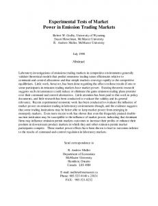
was 30 K and the voltage and current in the test circuit was increased incrementally. The experimental test results for the superconducting hybrid DC circuit breaker prototype with the highest fault current are shown in Fig. 3. Fig. 3 (a) presents the total current through the hybrid circuit breaker I and the current through the superconductor and mechanical switch Im. Fig. 3 (b) illustrates the voltage across the circuit breaker and the trigger signal for the vacuum interrupter sent by the microcontroller. The resistance of the superconducting coil was calculated by using the circuit breaker voltage minus the coil inductive voltage drop and then divided by the current through the superconductor, which is displayed in Fig. 3 (c). This however is only valid when the vacuum interrupter has negligible voltage drop between the contacts when it is closed. The impedance of the superconductor therefore was only displayed until 3.4 ms when the interrupter contacts opened. Initially the superconducting hybrid DC circuit breaker prototype is subjected to a normal operating current of 50 A. The IGBT is kept off and normal current flows through the superconducting coil and the vacuum interrupter. The fault is applied at t0 0.9 ms when the switch connected in parallel with the load resistor is short-circuited. When the fault is applied, the current starts to rise rapidly. The rate of rise of the fault current is limited in the prototype test rig by the maximum slew rate of the DC power supply, which is 300 A/ms. A voltage spike appears across the circuit breaker due to the inductance of the superconducting coil and the rise of the fault current. The prospective fault current without any current limiting action would be 500 A. When the fault current reaches 200 A at 30 K, the superconducting coil starts to quench and develops resistance. The vacuum interrupter actuator is triggered by the microcontroller at t1, which is 0.9 ms after the fault is applied. The superconducting coil starts to quench at a point on the wire where the critical current is lowest. This introduces a small resistance but the resistance increases as the quench progresses along the wire with the fault current between 200 A and 330 A. The fault current in the primary branch is eventually limited to 330 A by the superconducting coil. Without the superconducting coil, the fault current would increase to 500 A. The current then decays from 330 A to 160 A as the resistance of the superconducting coil continues to increase due to the increasing temperature of the quenched sections in the coil. At t2 3.4 ms, the microcontroller sends a signal to turn on the IGBT and the current is commutated from the superconducting coil and vacuum interrupter to the IGBT due to the resistance difference between the primary and secondary branches. The current in the vacuum interrupter is reduced to a quasi-steady state value of 30 A at t3 4.2 ms when the vacuum interrupter opens, breaking the remaining current. TABLE I ESTIMATED QUENCH CURRENTS VERSUS TEMPERATURE Temperature (K)
Quench current (A)
32 30 28 25
113 192 235 360
4
500 Total current I Mech switch Im 400
Current (A)
(a) 300
200
100
0
0.9
1.6
6
5
4
3
2
1
0
0.8
1.1
180 DC circuit breaker Mech trigger signal
Voltage (V)
120
(b) 60
0
-60
2
1
0
6
5
4
3
4.5 0.1 Superconductor Rsc
Resistance (Ω)
0.08
(c) 0.06
0.04
residual system energy is absorbed by the varistor and the current finally decreases to zero. The experimental results show that this hybrid DC circuit breaker successfully interrupted 500 A DC current within 4.4 ms from the fault inception. At t2 3.4 ms the IGBT is turned on and the majority of the fault current is commutated into the secondary branch. In the test, a high increase in the fault current at this point is observed. This is due to no series inductance used, resulting in the high fault current transient responding to the change in the circuit breaker impedance. No series inductance was used to obtain the high rate of change of current in this test. In future testing when a series inductance of the order of a few hundred µH is used, this rapid increase in current would not be seen. It also should be noted that the ‘shoulders’ of the circuit breaker current shown in Fig. 3 (a) are related to the response of the DC power supply to the load short circuit condition. Fig. 3 (c) clearly shows that the resistance of the superconducting coil is 0.095 Ω at 3.4 ms. The quench resistance in this case is low because the maximum current is only 1.65 times the quench current. As a low voltage supply was used in the test, the quench resistance of the coil is sufficient to limit the fault current. Faster quenching of the superconductor would be achieved in systems with high rates of rise of fault current and high fault current levels. The superconducting hybrid DC circuit breaker used a superconductor in a novel manner to commutate the current from the primary branch into the secondary branch. This topology has the significant advantage of zero conduction losses during normal state operation. The passive nature of the commutation method means that the operating time can be reduced because the commutation occurs without needing a specific active detection signal (and time). The passive nature of the commutation also means that this breaker is more robust and is not affected by as many internal faults as other designs which require active measurement and control to perform the commutation.
0.02
IV. CONCLUSION 0 0
2
1
6
5
4
3 Time (ms)
t0
t1
t2
t3
t4
Fig. 3. Superconducting hybrid DC circuit breaker experimental test results at 30 K.
The moving coil actuator takes 2.5 ms to open the vacuum interrupter, which is much faster than a permanent magnet actuator due to the light moving mass [13, 14]. The Thomson coil actuator is able to open the vacuum interrupter within 1 ms but the operating efficiency is low [13, 15]. The moving coil actuator was designed and used here as a compromise between the operating speed and efficiency. The current in the IGBT increases to 500 A due to the low resistance presented to the DC power supply and is turned off at t4 5.3 ms, which is approximately 1.1 ms after the contacts of the vacuum interrupter open. This allows the vacuum interrupter to recover its voltage withstand level. The voltage across the DC circuit breaker increases to 175 V after the IGBT is turned off. The
A superconducting hybrid DC circuit breaker has potential for providing low loss and high speed interruption of fault current. A low voltage, low current prototype has been built and demonstrated interruption of 500 A DC current within 4.4 ms from the fault initiation. The experimental tests validated the operating principle of the proposed superconducting hybrid DC circuit breaker. In practical applications, the voltage and fault current levels will be high and this high fault current will make the superconducting coil quench uniformly and naturally develop a higher quench resistance quickly. The operating speed of the superconducting hybrid DC circuit breaker heavily depends on the operating speed of the vacuum interrupter actuator, which needs to be further improved. This hybrid superconducting option would represent a competitive candidate DC circuit breaker after optimization, in particular for hybrid electric aerospace applications where the cryogenic systems are already being considered for the electrical propulsion systems.
5
REFERENCES [1]
[2]
[3]
[4]
[5]
[6]
[7]
[8] [9] [10]
[11]
[12]
[13]
[14]
[15]
N. Flourentzou, V. G. Agelidis, and G. D. Demetriades, “VSC-based HVDC Power Transmission Systems: an Overview,” IEEE Trans. Power Electron., vol. 24, no. 3, pp. 592-602, Mar. 2009. T. M. Haileselassie, and K. Uhlen, “Power System Security in a Meshed North Sea HVDC Grid,” Proc. IEEE, vol. 101, no. 4, pp. 978-990, Feb. 2013. J. G. Dedecca, and R. A. Hakvoort, “A Review of the North Seas Offshore Grid Modeling: Current and Future Research,” Renewable and Sustainable Energy Reviews, vol. 60, pp. 129-143, Jul. 2016. T. An, G. Tang, and W. Wang, “Research and Application on Multiterminal and DC Grids based on VSC-HVDC Technology in China”, High Voltage, vol. 2, no. 1, pp. 1–10 , 2017. X. Pei, O. Cwikowski, D. S. Vilchis-Rodriguez, M. Barnes, A. C. Smith and R. Shuttleworth, “A Review of Technologies for MVDC Circuit Breakers,” IECON 2016 - 42nd IECON, Florence, 2016, pp. 3799-3805. B. Xiang, Z. Liu, Y. Geng, and S. Yanabu, “DC Circuit Breaker using Superconductor for Current Limiting,” IEEE Trans. Appl. Supercond., vol. 25, no. 2, Apr. 2015, Art. ID. 5600207. B. Xiang et al., “Quenched Resistance Effects on a Superconducting Current-Limiting-Type DC Breaker,” IEEE Trans. Appl. Supercond., vol. 26, no. 7, Jun. 2016, Art. ID. 5603105. O. Cwikowski, R. Shuttleworth, and M. Barnes, “Apparatus and Method for Controlling a DC Current,” Patent WO 2014/177874 A2, Nov. 2014. R. Wang, W. J. Premerlani, A. Caiafa, and Y. Pan, “Hybrid directcurrent circuit breaker”, US 9654102 B2, May 2017. X. Pei, X. Zeng, A. C. Smith and D. Malkin, “Resistive Superconducting Fault Current Limiter Coil Design using Multi-strand MgB2 Wire”, IEEE Trans. Appl. Supercond., vol. 25, no. 3, Apr. 2015, Art. ID. 5602105. M. Tomsic, et al., “Development of Magnesium Diboride (MgB2) Wires and Magnets using in situ Strand Fabrication Method,” Physica C: Supercond., vol. 456, pp. 203-208, 2007. X. Pei, and A. C. Smith, “Experimental Tests of a Resistive SFCL Integrated with a Vacuum Interrupter”, IEEE Trans. Appl. Supercond., vol. 26, no. 3, Apr. 2016, Art. ID. 5601206. X. Pei, A. C. Smith, R. Shuttleworth, D. S. Vilchis-Rodriguez, and M. Barnes, “Fast Operating Moving Coil Actuator for a Vacuum Interrupter”, IEEE Trans. Energy Convers., vol. 32, no. 3, pp. 931-940, Sep. 2017. S. Fang, Q. Liu, H. Lin, and S. L. Ho, “A Novel Flux-Weakening Control Strategy for Permanent-Magnet Actuator of Vacuum Circuit Breaker,” IEEE Trans. Ind. Electron., vol. 63, pp. 2275-2283, Mar. 2016. A. Bissal, J. Magnusson, G. Engdahl, “Electric to Mechanical Energy Conversion of Linear Ultrafast Electromechanical Actuators based on Stroke Requirements,” IEEE Trans. Ind. Appl, vol. 51, pp. 3059-3067, Jul. 2015.