(CERN) is under way to develop accelerating structures which reach this performance. The centrepiece of the testing program is the nominal CLIC accelerating.
Proceedings of LINAC08, Victoria, BC, Canada
TUP057
DESIGN AND FABRICATION OF CLIC TEST STRUCTURES R. Zennaro, A. Grudiev, G. Riddone, A. Samoshkin, W. Wuensch, CERN, Geneva, Switzerland S. Tantawi, J. W. Wang SLAC, Menlo Park, USA T. Higo KEK, Tsukuba, Japan Abstract
THE VG1 FAMILY
Demonstration of an accelerating gradient of 100 MV/m at a breakdown rate of 10-7 is one of the key feasibility issues of the CLIC study. A high power RF test program both at X-band (SLAC and KEK) and 30 GHz (CERN) is under way to develop accelerating structures which reach this performance. The centrepiece of the testing program is the nominal CLIC accelerating structure [1], but also includes structures with different RF parameters, with and without wakefield damping waveguides and made with different fabrication technologies. The latter structures address as directly as possible the different aspects of the nominal CLIC structure. The design and objectives of the various Xband and 30 GHz test structures are presented and their fabrication methods and status are reviewed.
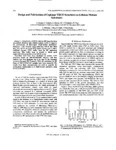
The design of vg1 is derived from the CLIC_C, a former CLIC nominal structure CLIC_C is strongly tapered with a group velocity which drops from 2.4%c to 0.65%c (values for the damped versions). The tapering results in a surface electric field of 300 MV/m in the last cell for the unloaded case as shown in Figure 1. Vg1 is a shortened version of CLIC_C, and is composed of the first 18 regular cells in order to limit the field on the surface to 265 MV/m for the unloaded case. The surface field for the loaded case is anyhow equivalent in the two cases as shown in Figure 1.
INTRODUCTION The accelerating structure test program is one of the highest priority activities of the CLIC study [2]. The two main aims of the testing program are to validate the present CLIC structure design, CLIC_G [1], and to acquire data from different structures which can be used to both improve the understanding of and validate models of fundamental high power limits [3, 4, 5] and the effect on performance of different aspects of the design, such as the presence of HOM damping waveguides. One of the main objectives for the structure is a loaded gradient of 100 MV/m with a 10-7 breakdown rate at the design pulse length. A second important objective is that the long range transverse wakefields be suppressed at the position of the second bunch to Wt,2 ≤ 6.6V/pC/mm/m for a bunch population N=4*109. In the CLIC structure this suppression is provided by combination of HOM damping waveguides located in each accelerating cell and detuning. Finally, the short range wakefield, which is determined by the aperture of the irises and is proportional to the bunch charge must remain below the threshold provided by the beam dynamics study. The test structures can be organized into four groups: the VG1 family which is based on the design of the former nominal CLIC structure, CLIC_G family which is based on the present CLIC structure, the C10 family which is used to investigate specific issues in a simple constant impedance design with reusable couplers and 30 GHz structures which are now dedicated to the study of new ideas and to acquire more data for the understanding of the breakdown physics.
Electron Accelerators and Applications
vg1
Figure 1: CLIC_C with accelerating gradient (MV/m, red), field on surface (MV/m, green), power (MW, black) and pulsed surface heating (K, blue) along the structure. vg1 extends to cell 18. The reduction in the number of cells has as consequence not only in the reduction of peak surface electric field, but also a reduction in the efficiency of the structure which drops to only 18% from the original 24% of CLIC_C as shown in Table 1. Table 1: Vg1 main parameters (undamped version). Name Frequency (GHz)
T18_vg2.6_disk 11.424
N cell
18+2
Phase advance/cell (deg)
120
Iris aperture ain,out (mm)
4.06/2.66
Iris thickness din,out (mm)
2.897/1.314
Vgin/out (%c) Tfilling (ns) (full structure) Pin unloaded (MW) (100 MV/m) Pin loaded (MW) (100 MV/m) Pulse length (ns) P/c (Wu) Efficiency (%)
2.61/1.02 36 55.5 63.7 267.4 15.0 17.7
1E - Colliders 533
TUP057
Proceedings of LINAC08, Victoria, BC, Canada
The basic vg1 design has been used to address a number of basic structure features, experimental issues, and technology choices. The first question the structure addresses is the achievable gradient given the iris dimensions. A first structure (T18_vg2.4_disk) made using diamond turning and bonding techniques developed by the NLC/JLC program has been tested [6] and has produced excellent results largely in agreement with predictions. In order to demonstrate the reproducibility of the results another four equivalent structures are being fabricated. The test of T18_vg2.4_disk demonstrates the potential of the structure but without the complication of the damping waveguides. The damping waveguides result in a surface magnetic field enhancement (Hs/Ea) of about 4.5 mA/V (~2.5 mA/V for the undamped case), a group velocity change of about 15% and may influence the dynamics of breakdown in an unknown way. For this reason a damped version of the vg1 (TD18_vg2.4_disk) is next most important step in the test programme. A picture of an undamped disk of the test structure is shown in Figure 2.
Figure 2: A single disk of TD18_vg2.4_disk. The TD18_vg2.4_disk machined with a combination of diamond turning for the cell iris and disk faces and milling for the outer cavity wall and damping waveguides. Three structures are under production. Two of them will be brazed at SLAC at high temperature (~1015 deg) in a hydrogen furnace. The brazing will be followed by conventional vacuum baking at 650 deg to remove hydrogen from the bulk. The third structure will be brazed at 820 degrees in a vacuum oven and no successive baking is required. Another two units of the damped version of the vg1 are under fabrication but in this case using the technology of clamped quadrants (TD18_vg2.4_quad) as shown in Figure 3.
Figure 3: A single quadrant of TD18_vg2.4_quad. The advantage of clamped quadrants is to give the possibility to avoid the heating associated with brazing Electron Accelerators and Applications 534
and thus gives the possibility of using high-strength copper alloys. Alloys such as copper zirconium (Zr ~0.2% in weight) have a much higher fatigue strength than normal OFE copper [7]. The estimated fatigue limit for cold worked copper zirconium is much larger than the one of pure copper allowing a pulsed temperature rise of ΔT=77K instead of 48K. Even in case of brazing, copper zirconium still has better thermal fatigue strength than cold worked pure copper although its conductivity drops to only 80% of the conductivity of copper. To compare the breakdown performances of copper zirconium and conventional OFE copper, one of the two units of TD18_vg2.4_quad is made out of copper zirconium and the second is made out of OFE copper.
THE CLIC_G FAMILY CLIC_G is the present nominal CLIC structure. Compared to CLIC_C, it has a lower peak surface electric field, 245 MV/m instead of 294 MV/m, and lower pulsed surface heating, 53 K instead of 71 K. The reduction of the peak electric field is due to a weaker tapering and the reduction of the pulsed surface heating is related to shorter pulses with 240 ns instead of 296 ns. The value of the 64 MW input power is nearly the same as for CLIC_C as is the value of P/C. Both damped and undamped versions have been designed for 11.424 GHz and also for 11.994 GHz, the nominal CLIC frequency. The 12 GHz versions will be tested in the two beam test stand at CERN [8]. The basic parameters of the undamped test structure in disk at 11.424 GHz (T24_vg1.8_disk) are presented in Table 2. Table 2: CLIC_G main parameters (undamped version). Name Frequency (GHz) N cell Phase advance/cell (deg)
T24_vg1.8_disk 11.424 24+2 120
Iris aperture ain,out (mm)
3.307/2.467
Iris thickness din,out (mm)
1.753/1.050
Vgin/out (%c) Tfilling (ns) (full structure)
1.82/0.93 59
Pin unloaded (MW) (100 MV/m) Pin loaded (MW) (100 MV/m) Pulse length (ns) P/c (Wu)
44.2 55.7 239 14.7
Efficiency (%)
30.5
All the X-band test structures currently under production make use of mode launcher couplers to pass from rectangular to circular waveguide which is axially coupled to the structure. This can be seen in Figure 3 Mode launcher couplers require additional length so cannot be used in CLIC. A compact coupler is currently being developed. A version of CLIC_G with waveguide feeders directly connected to the matching cell via magnetic coupling has been developed and a damped test 1E - Colliders
Proceedings of LINAC08, Victoria, BC, Canada
structure will follow. The matching cell of the coupler is equipped with four waveguides, two for damping and two dual purpose waveguides for RF input plus damping. The coupler design has a magnetic field enhancement which is lower than in the regular cells for an equivalent accelerating gradient. A damped version of CLIC_G in copper-zirconium is also included in the test program for comparison to pure copper. In this case the structure is made out of disks and requires high temperature bonding. The resistivity of the copper will be increased by 25% which requires an additional RF power of respectively 6% and 12% for loaded and unloaded cases.
THE C10 FAMILY The role of C10 structures are to provide a standard and well benchmarked geometry that is simple and inexpensive to build and exploits the reusable couplers already developed at SLAC. Features of structures such as iris diameter, damping features and material can all be directly tested. In addition the constant impedance geometry provides a clear geometrical reference point without the effect of tapering. C10s will provide information on the direct effect of geometrical parameters on the breakdown rate. Four different designs based on different combination of radius and thickness have been considered and summarized in table3. Table 3: C10 main parameters; a is iris radius and d is iris thickness. C10_vg0.7 C10_vg1.35 C10_vg2.25 C10_vg3.3
a (mm) 2.53 3 3.88 3.88
d (mm) 1.66 1.66 2.79 1.66
Vg (%c) 0.7 1.35 2.25 3.3
At least two structures of each design are under fabrication. The test of repeatability will provide much information on the performance of C10_vg_1.35 that is produced in four units; for this reason it is taken as undamped reference for testing the effect of damping features on the breakdown rate. A version of C10_vg_1.35 with damping waveguides is already designed (CD10_vg_1.35) and a second structure, which has radial choke damping, has been proposed.
30 GHz TEST STRUCTURES The programme for 30 GHz structures makes use of the CTF3 facility [9] and emphases the test of novel ideas. For example the so called “speed bump” has recently been tested, although not yet analyzed. The particularity of the speed bump, which is a constant impedance structure, is the use of the TM03 mode for the input matching cell in order to locally reduce the group velocity. In the structure regular cells group velocity is 4.7% but is only 1.7% in the matching cell. This drop of the group velocity reduces the bandwidth which is expected to diminish the damage due to the breakdown in the first regular cell by limiting the transient feeding of Electron Accelerators and Applications
TUP057
power to the breakdown. The first cell is normally the one most damaged by breakdown. Apart from the matching cell the structure is identical to the 2π/3 Cu [10] which was tested in 2006. Another structure which has been produced in 2008 is the so called “TM02” which has regular cells that are identical to the ones of the 2π/3Cu with the exception of the diameter which is very large in order to use the TM02 propagating mode. This mode has the the same P/C, the same electric field enhancement and the same Sc but different group velocity, which drops from 4.7%c to 2.0%c. The use of the TM02 mode drastically changes the group velocity without modifying local fields near the iris. The test of the TM02 could provide good indications on the eventual direct effect of the group velocity on the breakdown rate. The final structure of the planned testing program is a scaled version of the NLC T24 structure which is currently under test in SLAC is also scheduled in order to check the effect on the breakdown rate of frequency scaling.
CONCLUSION The possibility to reach 100 MV/m at 10-7 repetition rate for the nominal pulse length has been demonstrated by the T18_vg2.6_disk. The testing program continues with the objective to reach the same gradient with a higher efficiency structure (CLIC_G) and with the HOM damping waveguides. Studies on different technologies and materials are underway to address the issue of pulsed surface heating.
REFERENCES [1] A. Grudiev, “Design of X-band accelerating structure for the CLIC main linac”. This conference. [2] http://clic-study.web.cern.ch/CLIC-Study/. [3] A. Grudiev “A new local field quantity describing the high gradient limit of accelerating structures”. This conference. [4] W. Wuensch, Progress in Understanding the High Gradient Limitations of Accelerating Structures, CLIC-Note-706 - Geneva, CERN, 08 Mar 2007. [5] O.A. Nezhevenko, “On the Limitations of Accelerating Gradient in Linear Colliders Due to the Pulsed Heating,” Proceedings of PAC97, Vancouver 1997, p.3013. [6] S. Doebert et al., “High Power test of a low group velocity X-band Accelerator Structure for CLIC”. This conference. [7] S. Heikkinen, “Study of High Power RF Induced Thermal Fatigue in the High Gradient Accelerating Structures”, Helsinki University of Technology, 2008 (pending). [8] http://ctf3-tbts.web.cern.ch/ctf3-tbts/. [9] http://ctf3.home.cern.ch/ctf3/CTFindex.htm. [10] R. Corsini et al., “A High-Gradient Test of a 30-GHz Copper Accelerating Structure” Proceedings of LINAC96, Knoxville, Tennessee USA 1996, p.761. 1E - Colliders 535